
Related Manuals for Panasonic AG-UMR20P


Summary of Contents for Panasonic AG-UMR20P
-
Page 1: Operating Instructions
Operating Instructions Memory Card Portable Recorder AG-UMR20P Model No. AG-UMR20E Please read these instructions carefully before using this product, and save this manual for future use. ENGLISH PJ EJ DVQP1321ZA F0517SQ0... - Page 2 Hrvatski Suomi Magyar Português http://pro-av.panasonic.net/en/manual/index.html - 2 -...
-
Page 3: Information For Your Safety
Information for Your Safety WARNING: To reduce the risk of fire, electric shock or product damage, ≥ Do not expose this unit to rain, moisture, dripping or splashing. ≥ Do not place objects filled with liquids, such as vases, on this unit. ≥... - Page 4 Warning Risk of fire, explosion and burns. Do not disassemble, heat above 60 oC (140 oF) or incinerate. ≥ We recommend using Panasonic batteries (VW-VBD58/AG-VBR59/AG-VBR89/AG-VBR118). ≥ If you use other batteries, we cannot guarantee the quality of this product. ≥ Do not heat or expose to flame.
-
Page 5: Important Safety Instructions
Battery pack (Lithium ion battery pack) ≥ Use the specified unit to recharge the battery pack. ≥ Do not use the battery pack with equipment other than the specified unit. ≥ Do not get dirt, sand, liquids, or other foreign matter on the terminals. ≥... - Page 6 Declaration of Conformity Model Number: AG-UMR20P Trade Name: Panasonic Responsible Party: Panasonic Corporation of North America Two Riverfront Plaza Newark NJ07102 Support contact: 1-800-524-1448 This device complies with Part 15 of the FCC Rules. Operation is subject to the following two conditions: (1) This device may not cause harmful interference, and (2) this device must accept any interference received, including interference that may cause undesired operation.
-
Page 7: Before Use
Disposal may be regulated in your community due to environmental considerations. For disposal or recycling For your safety, please read the following text carefully. information, please visit Panasonic website: http:// This appliance is supplied with a moulded three pin www.panasonic.com/environmental or call 1-888-769- mains plug for your safety and convenience. - Page 8 <For India only> AEEE Yönetmeliğine Uygundur. AC adaptor information AEEE Complies with Directive of Turkey. IS 616/IEC 60065 Note regarding the Power Management function specified under COMMISSION REGULATION (EC) No 1275/2008 implementing Directive 2009/125/EC of the European Parliament and of the Council. This device is designed and manufactured for use at a broadcasting station and/or in a similar environment.
- Page 9 ≥ When storing the unit, it is recommended that you (AG-UCK20G) place a desiccant (silica gel) in with it. ≥ Always use a genuine Panasonic Camera head option About terminal protection cable (AG-C20003G (3 m (118-1/8 q)), AG-C20020G ≥ When not using the connecting terminal, please attach (20 m (787-3/8 q)): optional).
- Page 10 About the battery (optional) About the AC adaptor (supplied)/ battery charger (optional) The battery used in this unit is a rechargeable lithium-ion battery. It is susceptible to humidity and temperature and ≥ If the temperature of the battery is extremely high or the effect increases the more the temperature rises or extremely low, charging may take time or the battery falls.
-
Page 11: Lcd Monitor
About the SD card (optional) About operation from the Web screen When disposing of or giving away the SD card, note It is possible to distribute the streaming image of the unit that: (IP image transmission) or change the setup of the unit ≥... - Page 12 ∫ About combination of Memory Card ∫ Disclaimer of warranty Portable Recorder and Compact IN NO EVENT SHALL Panasonic Corporation BE LIABLE TO ANY PARTY OR ANY PERSON, EXCEPT Camera Head FOR REPLACEMENT OR REASONABLE This unit (AG-UMR20) is compatible only to the MAINTENANCE OF THE PRODUCT, FOR THE CASES, dedicated camera head AG-UCK20G.
- Page 13 Please 1 Leakage or theft of information through the unit note that Panasonic does not accept any responsibility 2 Use of the unit for illegal operations by persons with for the compromise, manipulation, and loss of malicious intent information caused by these events.
- Page 14 ≥ Functions which can be used by Windows only are indicated using the mark. ≥ These operating instructions are designed for use with models AG-UMR20P/AG-UMR20E. The illustrations and screen examples used in this document are of the AG-UMR20P. - 14 -...
-
Page 15: Table Of Contents
Contents USER button ............65 Information for Your Safety ........3 Accessories .............. 17 Setting the USER button ........65 Optional accessories ..........17 Using the USER button ........66 Functions of the USER button......67 Preparation Useful functions ............76 Using the SHIFT button ........ - Page 16 Menu Menu structure ............194 Using the Menu ............200 [SCENE FILE]............ 200 [SW SETUP] ............207 [RECORD SETUP] ..........211 [TC/UB SETUP] ..........215 [AUDIO INPUT] ..........216 [USER SW] ............217 [OUTPUT SETUP] ..........218 [CARD FUNCTION] ........... 220 [DISP SETUP] ...........
-
Page 17: Accessories
Accessories Check the accessories before using this unit. Keep the accessories out of reach of children to prevent swallowing. AC adaptor AC cable (AG-UMR20P) (AG-UMR20E) For U.K. and Saudi Arabia (AG-UMR20E) For Continental Europe, etc. Caution for AC Mains Lead... -
Page 18: Preparation
Preparation What you can do with this unit Recording to the SD card It is possible to record motion pictures and still pictures to the SD card using a variety of recording functions. ≥ This unit supports relay recording using double card slots. Connecting to the Camera Head (optional) to record (CAM Mode) It is possible to connect to the Camera Head and record onto an SD card. -
Page 19: Linking To External Devices
Linking to external devices Connection to a PC (USB connection) Transfer data (files) to perform nonlinear editing on another device (PC, etc.). ≥ This unit supports USB 2.0. A SD card B USB 2.0 cable (A-miniB type) C PC SD cards are optional and not supplied with this unit. -
Page 20: Network Connection
Network connection Connection with remote camera controller This unit supports the remote camera controllers AW-RP50/AW-RP120 and the remote operation panel AK-HRP200. (Connection example) SIGNAL GND POWER TO PAN/TILT HEAD 12V IN TALLY/GPI BOOT ... - Page 21 Connection to PC/mobile terminal This unit can display an IP image on a PC connected to the network via wired LAN or a mobile terminal connected via a wireless access point. (Connection example) ...
-
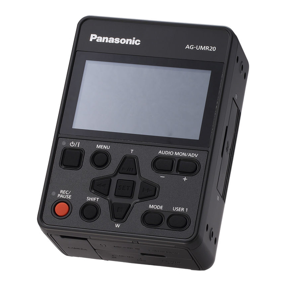
Page 22: Names And Functions Of Main Parts
Preparation Names and Functions of Main Parts 11 12 13 14 15 16 17 18 19 20 25 26 24 21 22 23 Exhaust opening (cooling fan) LCD monitor (Touch screen) Speaker Power button [ DC input terminal [DC IN] 24, 226) Menu button [MENU] ≥... - Page 23 35 36 Inlet (cooling fan) Battery release button [PUSH] Battery holder SD Card slot cover Access lamp (card 1) Card slot 1 Card slot 2 Access lamp (card 2) Setting legs - 23 -...
-
Page 24: Power Supply
To ensure that safe products are used we would recommend that a genuine Panasonic battery pack is used. ≥ For information on how to charge the battery, refer to the Operating Instructions for the battery charger. -
Page 25: Inserting/Removing The Battery
Inserting/removing the battery Install the battery by inserting it in the direction shown in the figure. ≥ Insert the battery until it clicks and locks. Removing the battery Turn off the unit by pressing and holding the power button until the status indicator is turned off, and remove while holding with hand so it will not fall. -
Page 26: Charging And Recording Time
Charging and recording time Charging/Recording time Continuously recordable time Battery model Voltage/Capacity Charging System Frequency number (minimum) time setting 211) CAM Mode SDI Mode 59.94 Hz 6 h 40 min AG-VBR59 7.28 V/5900 mAh 3 h 20 min (optional) 50.00 Hz 3 h 10 min 6 h 50 min 59.94 Hz... -
Page 27: Preparation Of Sd Cards
The unit can record motion pictures or still pictures to an SD card. Cards that you can use with this unit ≥ The cards that you can use are correct as of April 2017. ≥ We recommend that you use a Panasonic Memory Card. Card type Capacity... -
Page 28: Inserting/Removing An Sd Card
Inserting/removing an SD card When using an SD card for the first time, it is necessary to format the SD card. 40) When the SD card is formatted, all of the recorded data is deleted. Once the data is deleted, it cannot be restored. Caution: Check that the access lamp has gone off. -
Page 29: Connecting This Unit To The Camera Head (Cam Mode)
Preparation Connecting this unit to the Camera Head (CAM Mode) ∫ Attaching the Camera head option cable (optional) Be sure to turn off the unit before attaching the Camera head option cable. A Camera head option cable Insert Camera head option cable D into this unit’s CAMERA terminal and the Camera Head connecting terminal. -
Page 30: Input Sdi To This Unit (Sdi Mode)
Preparation Input SDI to this unit (SDI Mode) HD SDI A Camera recorder (SDI output device) B SDI OUT terminal C BNC cable (commercially-available) Connect the SDI output device to this unit with a BNC cable. ≥ Use the 5C-FB compatible double shielded cable for the BNC cable (commercially available product) to connect to the SDI IN terminal and the SDI OUT terminal. -
Page 31: Turning The Unit On/Off
Preparation Turning the unit on/off ≥ The method for turning on the unit depends on the setting of [POWER UP OPTION]. 226) Press power button B for 2 seconds or more to turn on the unit. To turn off the unit ... -
Page 32: Selecting A Mode
Preparation Selecting a mode Switching between the CAM Mode and the SDI Mode Always turn off this unit and turn it on again when switching between the SDI Mode and the CAM Mode. ≥ Connect this unit and the Camera Head when switching to the CAM Mode. ≥... -
Page 33: Switching Between Recording Mode And Playback Mode
Switching between Recording Mode and Playback Mode When [PRIORITY MODE] is set to [REC/PB] or [REC/PB(4K)], press the MODE button to switch between Recording Mode and Playback Mode. ≥ If set to [IP], [IP(4K)], even if the MODE button is pressed, this unit will not enter Playback Mode. Press the MODE button A to switch between Recording Mode and Playback Mode. -
Page 34: Using The Menu Screen
Preparation Using the menu screen Menu setting by button operation Press the MENU button Press the buttons to move the cursor to the menu, and press the SET button to select. Place the cursor on [EXIT] and press the SET button to finish the menu setting. ∫... -
Page 35: Menu Setting By Touch Screen Operation
Menu setting by touch screen operation Press the MENU button Touch the top menu A. Touch the submenu B. ≥ Next (Previous) page can be displayed by touching Touch the desired item to enter the setting. Touch [EXIT] to exit the menu setting. How to use the touch screen You can operate by directly touching the LCD monitor (touch screen) with your finger. -
Page 36: Setting Date And Time
Preparation Setting date and time When this unit is turned on, the message [SET TIME ZONE AND DATE/TIME] may appear. To make these settings, select [YES], and follow the instructions from Step 2-3 of the time zone setting procedure. Time zone Time difference from the Greenwich Mean Time can be set. - Page 37 ∫ Time zone table Time Time Region Region difference difference 0:00 London, Casablanca r3:30 Tehran s1:00 Azores r4:00 Dubai, Abu Dhabi Fernando de Noronha Kabul s2:00 r4:30 Rio de Janeiro, Sao Paulo, Buenos Aires Islamabad, Karachi, Male s3:00 r5:00 Newfoundland Delhi, Kolkata, Mumbai, Chennai, s3:30 r5:30...
-
Page 38: Adjusting The Lcd Monitor
Preparation Adjusting the LCD monitor ≥ These settings will not affect the images actually recorded. [POWER LCD] This makes it easier to view the LCD monitor in bright places including outdoors. Select the menu. : [DISP SETUP] # [POWER LCD] # [+1] (Makes brighter)/[0] (Normal)/[-1] (Makes less bright) [LCD SET] It adjusts brightness and color density on the LCD monitor. -
Page 39: Recording
Recording Before recording ≥ When recording, make sure your footing is stable and there is no danger of colliding with another person or object. ≥ When you are outdoors, record pictures with the sunlight behind you. If the subject is backlit, it will become dark in the recording. -
Page 40: Selecting A Media To Record
≥ After you have changed the system frequency, this unit will be restarted automatically. ≥ By default, the system frequency is set to the broadcasting system of the region where this product was purchased. ≥ AG-UMR20P: This function’s default setting is [59.94Hz]. AG-UMR20E: This function’s default setting is [50.00Hz]. -
Page 41: Record On Sd Card
Recording Record on SD card Set [PRIORITY MODE] to [REC/PB] or [REC/ PB(4K)] to switch to Recording Mode. 32, 33) Press REC/PAUSE button A to start recording. ≥ When recording starts, REC (red) appears on the screen and the tally lamp lights up. ≥... - Page 42 ≥ (Maximum recordable scenes of a single SD card) PRIORITY MODE REC/PB(4K) REC/PB Recordable clips Approx. 89100 Approx. 3900 Different dates Approx. 900 Approx. 900 ≥ The maximum number of recordable clips and the maximum number of different dates will be smaller than the table above when there are both MP4 clips and still pictures recorded on the SD card.
-
Page 43: Switch Recording Mode
Recording Switch Recording Mode There are four Recording Mode presets according to the recording situation on this unit. ([AUTO]/[F1:]/[F2:]/[F3:]) Touch the appropriate operation icon to switch between Auto Mode ([AUTO]) and Manual Mode ([F1:], [F2:], [F3:]). Touch to switch between Auto Mode and AUTO AUTO F1: F2: F3: Manual Mode. -
Page 44: Adjusting The Picture Quality
Recording Adjusting the Picture Quality You can set the picture quality of images to be recorded in the main menu # [SCENE FILE]. Detail function This function thickens or weakens the outlines of images. It effectively softens or sharpens images, but in some cases, the whole image may become rough due to emphasized noise and edges. - Page 45 Color matrix setup function This function sets color saturation and phase. It applies individual effect on 16 phases in an image. ∫ Menu item [MATRIX]: Loads the preset color matrix data and compensates the saturation and phase accordingly. 203) [COLOR CORRECTION Allows you to set the saturation and phase of each of the 16 image axes.
-
Page 46: Using The Zoom
Recording Using the zoom The unit can deliver a maximum optical zoom of 20k. ≥ You can check the zoom magnification on-screen, displayed as a value between Z00 and Z99. The value gets larger as you zoom in, and smaller as you zoom out. Press the buttons to zoom. -
Page 47: Image Stabilization
Recording Image stabilization Blurring of image can be decreased by the image stabilization. Optical image stabilization (O.I.S.) or hybrid image stabilization (Hybrid O.I.S.) can be used. Hybrid image stabilization is the image stabilization using both optical and electronic image stabilization. Register <O.I.S.>... -
Page 48: Focus
Recording Focus Adjust manually when the unit does not focus automatically. A Multi manual icon [FOCUS] B Focus value FOCUS MF50 ≥ Switch to Manual Mode. Perform menu setup for [FOCUS], and set to Manual Focus Mode. : [SW SETUP] # [FOCUS] # [MANUAL] ≥... - Page 49 ∫ To emphasize the outline of images Setting [LCD DETAIL] to [ON] helps you achieve focus easier by emphasizing the outlines of an image displayed on the LCD monitor. You can also adjust the emphasis level or change the frequency. ≥...
-
Page 50: Using The Push Auto Function
Using the PUSH AUTO function Auto High-Speed Focus ≥ Switch to Manual Focus Mode. Press the button while pressing and holding the SHIFT button. ≥ Auto Focus will be activated and the camera will perform high-speed focusing until the image is focused. ≥... -
Page 51: Focus Assist
Focus Assist A color is displayed on the part that is focused when Focus Assist is used. (Peaking display) ≥ Switch to Manual Focus Mode. Press the button while pressing and holding the SHIFT button. ≥ Press again to cancel. : Peaking ... -
Page 52: White Balance
Recording White Balance Automatic White Balance function may not reproduce natural colors depending on the scenes or lighting conditions. If so, you can adjust the White Balance manually. A White Balance B Multi manual icon [WB] ≥ Switch to Manual Mode. Perform menu setup for [WHITE BALANCE MODE], and switch the mode for White Balance. - Page 53 To set ATW Lock You can set ATW Lock by registering <ATW LOCK> to a USER button. ≥ Please refer to page for details about setting the USER button. Set the White Balance mode to [ATW]. Press the USER button to which <ATW LOCK> is registered or touch the applicable USER button icon.
-
Page 54: Iris/Gain Adjustment
Recording Iris/Gain adjustment When recording a scene that is too dark (or bright) or a scene in a similar situation, manually adjust the iris and gain. Iris adjustment A Iris value B Auto iris icon C Multi manual icon [IRIS] * It is displayed in Auto Iris Mode. - Page 55 To adjust the brightness during auto adjustment Brightness can be adjusted by setting [AE LEVEL], [BACKLIGHT COMPENS.]/<BACKLIGHT>, [SPOTLIGHT COMPENS.]/<SPOTLIGHT> when the Auto Mode is set, or when one of [IRIS MODE], [GAIN MODE], or [SHUTTER MODE] is set to [AUTO]. ∫...
-
Page 56: Gain Adjustment
Gain adjustment A Gain value ≥ In Auto Gain Mode, “AGC” is displayed; in Manual Gain Mode, the gain value is displayed in dB. B Multi manual icon [GAIN] GAIN ≥ Switch to Manual Mode. Perform menu setup for [GAIN MODE], and set to Manual Gain Mode. : [SW SETUP] # [GAIN MODE] # [MANUAL] Confirm that the multi manual icon [ GAIN] (yellow display: Function Selection Mode) is... - Page 57 ∫ Changing the maximum possible gain value for Auto Gain Mode Select the menu. : [SW SETUP] # [AGC LIMIT] # desired setting [3 dB]/[6 dB]/[9 dB]/[12 dB]/[15 dB]/[18 dB]/[21 dB]/[24 dB]/[27 dB]/[30 dB] Super Gain Super Gain allows you to set the gain value to 33 dB or 36 dB. ≥...
-
Page 58: Manual Shutter Speed
Recording Manual shutter speed Adjust the shutter speed when recording fast-moving subjects. A Shutter speed B Auto Shutter display ≥ This is displayed in Auto Shutter Mode. C Multi manual icon [SHUTTER] A.SHTR 1/60 SHUTTER ≥ Switch to Manual Mode. Perform menu setup for [SHUTTER MODE] and set to Manual Shutter Mode. - Page 59 ≥ The shutter speed cannot be adjusted in the following cases: j During Freeze Frame ≥ You may see a band of light around an object that is shining very bright, or highly reflective. ≥ During normal playback, image movement may not look smooth. ≥...
-
Page 60: Audio Input
Recording Audio Input This unit can record audio in 2 ch. It is possible to switch to the built-in microphone of the camera head, microphone of the SDI output device, external microphone, and connected audio device. ∫ About audio recording methods The audio recording method varies depending on the [PRIORITY MODE] setting. -
Page 61: Adjusting The Audio Input Level
Adjusting the audio input level Selecting an adjustment method Adjustment method of the audio input level can be selected. Perform menu setup for [AUDIO LEVEL]. : [AUDIO INPUT] # [AUDIO LEVEL] # desired setting AUTO Adjusts the level automatically. MANUAL Adjusts the level manually. -
Page 62: Counter Display
Recording Counter display You can change a counter display that indicates how much time has elapsed during recording or playback. Switch the counter display by pressing the USER button assigned as <COUNTER>, or touching the USER button icon. ≥ Please refer to page for details about setting the USER button. - Page 63 [DF MODE] Select the compensation mode for the time code. ≥ Set [SYSTEM FREQ] to [59.94Hz]. Select the menu. : [TC/UB SETUP] # [DF MODE] # desired setting [DF]: Time code is compensated in accordance with the actual time. It is mainly used for broadcasting such as TV programs.
-
Page 64: Setting The User Information
Setting the User Information Eight digit hexadecimal alphanumeric can be entered and displayed as a memo information such as dates, control numbers, etc., into the User Information. UB 00 00 00 00 ≥ This is displayed only when [PRIORITY MODE] is set to [REC/PB] or [IP]. [UB PRESET] You can set the User Information. -
Page 65: Using The Tc Data Of The Sdi Output Device
Using the TC data of the SDI output device The values of the time code and the users bit to be recorded in the SDI Mode can be selected by setting [SDI REGEN]. Select the menu. : [TC/UB SETUP] # [SDI REGEN] [ON]: Records the value of S-LTC area of the camera recorder connected to the SDI IN terminal. -
Page 66: Using The User Button
Using the USER button Either press the set USER1 button or touch the USER 2 to 13 USER button icons while the operation icons are displayed. (When you use the USER1 button) (When you use the USER2 to USER13 button) [USER2] [USER13] [USER3]... -
Page 67: Functions Of The User Button
Functions of the USER button ∫ List of USER button functions Mode that can be used Item Icon Function CAM Mode SDI Mode <INHIBIT> ― Invalid ± ± <ATW LOCK> [ATW.L] ATW Lock ± <BACKLIGHT> [B.Light] Backlight Compensation ± <SPOTLIGHT> [S.Light] Spotlight Compensation ±... - Page 68 <ATW LOCK> ≥ Register <ATW LOCK> to a USER button. This sets the White Balance mode to [ATW LOCK]. <BACKLIGHT> ≥ Register <BACKLIGHT> to a USER button. ≥ Set to Auto Mode 43) or set one of [IRIS MODE], [GAIN MODE] or [SHUTTER MODE] to [AUTO] 207, 208) Switches to automatic control to compensate the backlight.
- Page 69 <FRZ FRAME> ≥ Register <FRZ FRAME> to a USER button. Freezes the image on the unit. will appear on the screen and flash. ≥ Freeze ≥ If you record a motion picture during Freeze Frame, the frozen image and sounds will be recorded. ≥...
- Page 70 <SCENE FILE> ≥ Register <SCENE FILE> to a USER button. You can save the scene file settings to the SD card or load them from the SD card to this unit. ∫ Saving scene file settings Press USER button or touch USER button icon in the recording screen. Touch [SAVE].
- Page 71 <REC CHECK> ≥ Register <REC CHECK> to a USER button. Approximately 3 seconds at the last of the clip recorded last can be played back. It will return to the recording screen once the playback is completed. ≥ The time code is not displayed during REC check. ≥...
- Page 72 <O.I.S.> ≥ Register <O.I.S.> to a USER button. Switches the on/off of the image stabilization. <ZEBRA> ≥ Register <ZEBRA> to a USER button. Parts where white saturation (color saturation) is likely to occur (extremely brightly lit or shiny parts) are displayed with diagonal lines (zebra pattern A).
- Page 73 <BARS> ≥ Register <BARS> to a USER button. The color bar convenient for picture quality adjustment of the external monitor can be displayed. ≥ Test tones can be output as audio signals from the headphone terminal or either of the external output terminals while color bars are displayed.
- Page 74 <DISP/MODE CHK> ≥ Register <DISP/MODE CHK> to a USER button. The screen display can be switched, and the information screen can be displayed. ∫ Switching screen display Press USER button or touch USER button icon in the recording screen. Simplified display !# Normal display ≥...
- Page 75 <LCD REVERSE> ≥ Register <LCD REVERSE> to a USER button. The LCD monitor can be displayed reversed vertically and horizontally. <ZOOM W>/<ZOOM T> ≥ Assign <ZOOM W> or <ZOOM T> to one of the USER buttons. Performs the zoom operation. <SLOT SEL>...
-
Page 76: Useful Functions
Recording Useful functions Using the SHIFT button Useful recording and shooting functions can be used by pressing designated buttons while pressing and holding the SHIFT button. ≥ Operation is not possible when the menu screen is displayed, except for the operation of turning on/off the LCD monitor. - Page 77 Displaying waveform The waveform display (WFM) can be switched. Press the button while pressing and holding the SHIFT button in the recording screen. ≥ When [WFM TYPE] is set to [WAVE] or [VECTOR], each press of the button enables/disables WFM. ≥...
-
Page 78: Using The Multi Manual Function
Switching on/off of the LCD monitor Press the USER1 button while pressing and holding the SHIFT button. ≥ The LCD monitor is turned off. It is turned on by pressing the same button again. ≥ The setup is canceled when the unit is turned off. ≥... - Page 79 To switch the function set in the recording screen Set so the function to be used can be selected. ≥ If the desired function cannot be selected, use the settings below. Functions Settings FOCUS AE LEVEL Set [SELECT SCENE] to [AUTO] or set [IRIS MODE], [GAIN MODE] or [SHUTTER MODE] to [AUTO] SHUTTER Set [SHUTTER MODE] to [MANUAL]...
- Page 80 ND filter The built-in optical ND filter (light intensity adjustment filter) can be switched. ≥ Use this when recording in sunny outdoor when the subject is too bright and the screen becomes washed out. A Recommended ND filter setting ND1/16 B ND filter setting ...
-
Page 81: Auto Rec Function
This unit can automatically start/stop recording following the AUTO REC signal input from the camera recorder connected to the SDI IN terminal. ≥ For information about supported devices, refer to the support desk section of the website below. http://pro-av.panasonic.net/ Select the menu. : [RECORD SETUP] # [AUTO REC INPUT] # desired setting [OFF]: Does not start/stop recording automatically. - Page 82 ∫ Switching the output method of AUTO REC Recording control of this unit and external device can be performed with the REC/PAUSE button by setting [SDI REMOTE REC LINK] to [ON]. Select the menu. : [OUTPUT SETUP] # [SDI REMOTE REC LINK] # desired setting [ON]: Performs the recording control of this unit and the external device with the REC/PAUSE button.
-
Page 83: Playback
Playback Clip/Still picture playback Set this unit to playback mode. Touch the play mode select icon A. Card display The selected card slot is displayed in yellow. Select the card slot C you wish to play back. (When setting to clip Playback Mode) ... - Page 84 Touch the clip or the still picture to be played back. ≥ Next (Previous) page can be displayed by touching ≥ You can change the playback media by pressing the USER button to which <SLOT SEL> is registered. Select the playback operation by touching the operation icon. G Operation icon TC 00:02:30.00 TC 00:02:30.00...
- Page 85 ∫ Speaker/Headphone volume adjustment During clip playback, the speaker/headphone volume can be adjusted with the AUDIO MON/ADV i button and the AUDIO MON/ADV j button. Press the AUDIO MON/ADV i button or the AUDIO MON/ADV j button while playing back a clip.
-
Page 86: Motion Picture Playback Using Operation Icon
Motion picture playback using operation icon For details on the basic playback operations, refer to page 83. During Playback During Pause Direct playback bar Playback operation Button operation procedure Touch operation procedure Touch the LCD monitor and slide from Press the buttons while Skip playback right to left (from left to right) during... -
Page 87: Useful Functions
Playback Useful functions Creating still picture from clip You can save a frame of a recorded motion picture as a still picture. The picture size with which a still picture will be recorded differs depending on the picture size of [REC FORMAT] with which the clip was recorded. Recording format Aspect ratio Picture size... -
Page 88: Resuming The Previous Playback
Resuming the previous playback If playback of a clip was stopped halfway, the playback can be resumed from where it was stopped. Select the menu. : [PLAYBACK SETUP] # [RESUME PLAY] # [ON] If playback of a motion picture is stopped, appears on the thumbnail view of the stopped scene. -
Page 89: Editing
Editing Deleting scenes/still pictures Deleted clips/still pictures cannot be restored, so perform appropriate confirmation of the contents before proceeding with deletion. ≥ Press the MODE button to switch this unit to the Playback Mode. ∫ To delete the clip or still picture being played back Touch while clips or still pictures to be deleted are being TC 00:02:30.00... -
Page 90: Protecting Clips/Still Pictures
When you stop deleting halfway: Touch [CANCEL] or press MENU button while deleting. ≥ The clips or still pictures that have already been deleted when the deletion is canceled cannot be restored. To complete editing: Touch [Return] or press MENU button. ≥... -
Page 91: Copying Between Sd Cards
Editing Copying between SD cards Clips or still pictures recorded with this unit can be copied between the SD cards inserted in this unit. ≥ Copying is not possible if the type of the source SD card (SDHC Memory Card/SDXC Memory Card) is different from that of the target SD card. -
Page 92: Linking To External Devices
Linking to external devices Connecting Headphones, a Wired Remote Control or an External Monitor Headphones You can connect headphones (commercially-available) to the headphone output terminal (3.5 mm (0.14 q) diameter stereo mini jack). A Headphone output terminal ≥ Sound is not output from the speaker when headphones are connected. Wired Remote Control You can connect a wired remote control (commercially-available) to either of the CAM REMOTE terminals (FOCUS IRIS or ZOOM S/S). -
Page 93: External Monitor
External monitor You can connect this unit to an external monitor as shown in the figure below. HD SDI A HDMI Cable (commercially-available) B BNC cable (commercially-available) C External monitor ≥ More detailed 4K video can be enjoyed by connecting this unit to a 4K video compatible external monitor with a HDMI cable, and playing back MP4 clip. -
Page 94: Switching The Output Setup Of The Sdi Mode
Example of images with a [16:9] aspect ratio on an external monitor (4:3): [DOWN CONV.] setting [LETTERBOX] [SQUEEZE] ≥ When [DOWN CONV.] is set to [SIDE CROP], the sides of an image will be cut off, causing some icons on the external monitor to be hidden from the external monitor screen. - Page 95 About SDI input signal format SDI input signal format A is displayed in the screen of this unit during SDI Mode. It may not be possible to set [REC FORMAT] depending on the signal format. ≥ For setup of [REC FORMAT], refer to page 212. SDI IN 1080/59.94i ≥...
-
Page 96: Setting The External Output Resolution
Setting the external output resolution Change the setting for outputting images to an external monitor or other external device (recorder, etc.). Select the [OUTPUT SEL] menu. : [OUTPUT SETUP] # [OUTPUT SEL] # desired setting [SDI+HDMI]: Set this when outputting to both the SDI OUT terminal and the HDMI OUT terminal. [SDI]: Set this when outputting to the SDI OUT terminal. - Page 97 About external output resolutions The external output resolution varies depending on the [RESOLUTION] setting and connected terminal. ≥ Resolution of the external output will change depending on the number of pixels and frame rate of [REC FORMAT] when [RESOLUTION] is set to [SYSTEM] during the Playback Mode. ≥...
- Page 98 ≥ When [SYSTEM FREQ] is set to [50.00Hz] and [SDI MODE SEL] is set to [THROUGH] Setup of the [OUTPUT SEL] [RESOLUTION] SDI + HDMI (simultaneous output) HDMI Recording format setting HDMI OUT HDMI OUT SDI OUT terminal SDI OUT terminal terminal terminal 1080p...
- Page 99 ≥ When [SYSTEM FREQ] is set to [59.94Hz] and [SDI MODE SEL] is set to [NORMAL] Setup of the external output will change depending on the [29.97p/23.98p OUTPUT] setup. Setup of the [OUTPUT SEL] [RESOLUTION] SDI + HDMI (simultaneous output) HDMI Recording format setting...
- Page 100 ≥ When [SYSTEM FREQ] is set to [50.00Hz] and [SDI MODE SEL] is set to [NORMAL] Setup of the external output will change depending on the [25.00p OUTPUT] setup. Setup of the [OUTPUT SEL] [RESOLUTION] SDI + HDMI (simultaneous output) HDMI Recording format setting...
- Page 101 ∫ During SDI Mode Signal input to the SDI input is output to the external output of the SDI OUT terminal without any modification when [SDI MODE SEL] is set to [THROUGH]. ≥ For the signal format that the SDI input is possible, refer to page 95. ≥...
- Page 102 ≥ When [SYSTEM FREQ] is set to [59.94Hz] and [SDI MODE SEL] is set to [NORMAL] Setup of the external output will change depending on the [29.97p/23.98p OUTPUT] setup. Setup of the [OUTPUT SEL] [RESOLUTION] SDI + HDMI (simultaneous output) HDMI Recording format setting...
- Page 103 ∫ During Clip Playback Mode ≥ When [SYSTEM FREQ] is set to [59.94Hz] Setup of the external output will change depending on the [29.97p/23.98p OUTPUT] setup. Setup of the [OUTPUT SEL] [RESOLUTION] SDI + HDMI (simultaneous output) HDMI Recording format setting HDMI OUT HDMI OUT...
- Page 104 ≥ When [SYSTEM FREQ] is set to [50.00Hz] Setup of the external output will change depending on the [25.00p OUTPUT] setup. Setup of the [OUTPUT SEL] [RESOLUTION] SDI + HDMI (simultaneous output) HDMI Recording format setting HDMI OUT HDMI OUT SDI OUT terminal SDI OUT terminal terminal...
-
Page 105: Connecting To A Pc (File Transfer/Nonlinear Editing)
Linking to external devices Connecting to a PC (File transfer/nonlinear editing) When this device and a computer for editing are connected using a USB 2.0 Cable (commercially-available), image data in the SD card can be transferred. ≥ This unit supports USB 2.0. ≥... -
Page 106: Connecting To A Pc
Connecting to a PC miniB A USB 2.0 Cable (A-miniB type) (commercially-available) ≥ Insert the plugs as far as they will go. Connect this unit to the AC adaptor. ≥ Use the AC adaptor to free you from worrying about the battery running down. Turn on the unit. -
Page 107: About The Pc Display
About the PC display When the unit is connected to a PC, it is recognized as an external drive. ≥ Removable disk (Example: ) is displayed in [Computer]. Data recorded using AVCHD format has excellent compatibility with computers, due to its file form; however, it contains not just image and sound data, but also various important information, and it is associated using a folder structure which is like a figure. -
Page 108: Network Connection
Use the remote camera controller/ remote operation panel Up to a hundred units can be operated by IP connection from a Panasonic controller (AW-RP50, AW-RP120 and AK-HRP200). (The maximum length of the LAN cables is 100 meters (328 ft).) ∫ Controller supported ≥... -
Page 109: Menu Operation Method
Menu operation method Remote camera controller Camera Text Menu operation AW-RP50 AW-RP120 AK-HRP200 Press one of the [CAMERA STATUS/ Press and hold the [SELECT] SELECTION] buttons. button for about 2 seconds. ≥ The camera number in the camera number display area blinks. Selecting the unit to be Press the lit [UP]/[DOWN] button. - Page 110 ∫ To set menu items on the IP image The Camera Text Menu is displayed on the IP image as superimposed text by setting [DISPLAY MENU] 227) to [TEXT] and then performing the operation to display the Top Menu on the unit. ≥...
-
Page 111: Operation Method
Operation method For menu operation (Camera Text Menu), refer to page 109. Remote camera controller [AW-RP50] POWER ALARM CAMERA MENU PAGE GAIN/PED R/B GAIN R/B PED AWB/ABB SHUTTER EXIT STORE DELETE DETAIL SCENE/MODE CAMERA SETUP SYSTEM USER1 USER2 PRESET MEMORY / MENU ... - Page 112 ∫ Color temperature setting ([COLOR TEMP]) Press the [MENU] button on the AW-RP50. ≥ The [MENU] button lights, and the [PRESET MEMORY/MENU] buttons become selectable. Press the [4 (AWB/ABB)] button in the [PRESET MEMORY/MENU] area. ≥ The button lights, and the AWB/ABB menu appears on the LCD panel. Turn the [F1] dial to select “VAR”.
- Page 113 ∫ Assigning [COLOR TEMP] and [DIGITAL EXTENDER] to the [USER] buttons It is possible to assign off/on for the color temperature setting ([COLOR TEMP]) or for the digital extender function ([DIGITAL EXTENDER]) to the [USER] button. Press the [MENU] button on the AW-RP50. ≥...
- Page 114 Remote camera controller [AW-RP120] A For operating the Camera Text Menus. [CAMERA OSD]: When this is pressed for about 2 seconds, the selected camera menu is displayed, overlapping the camera output image. When it is pressed for about 2 seconds while a menu is displayed, the menu is exited. [F1]: Turn [F1] to move the cursor up and down in the Camera Text Menu or to change setting values.
- Page 115 ∫ Color temperature setting ([COLOR TEMP]) Press the [EXIT] button and the [ATW] button of [WHITE BAL] simultaneously. ≥ The [A], [B], and [ATW] buttons of [WHITE BAL] light, and color temperature setting mode is enabled. The color temperature setting value appears on the LCD screen during this time. Turn the [F1] dial to change the color temperature.
- Page 116 Remote Operation Panel [AK-HRP200] ≥ With the AK-HRP200, it is necessary to set [CAMERA TYPE] in [IP Mode] to [Remote IP]. For details, refer to the Operating Instructions for the AK-HRP200. A For operating the Camera Text Menus. When the [CHARA/MENU] button is pressed for about 2 seconds, the selected camera menu is displayed, overlapping the camera output image.
- Page 117 AG-UMR20 ± : Supported #: Supported with Control/display component Label Remarks some restrictions s : Not supported Auto setup switch [AUTO SETUP] [ WHITE BALANCE MODE ] is set to [ P5600K ] when 5600K switch [5600K] this switch is set to ON, ±...
- Page 118 AG-UMR20 ± : Supported #: Supported with Control/display component Label Remarks some restrictions s : Not supported Data set (up) [DATA SET UP] ± ND/ZOOM/FOCUS can also be adjusted. Data set (down) [DATA SET DOWN] ± [ND], [CC], [M.GAIN], Adjustment value display [SHT], [SYNC], ±...
- Page 119 AG-UMR20 ± : Supported #: Supported with Control/display component Label Remarks some restrictions s : Not supported Optical alarm display [OPT] Iris / master pedestal lock [IRIS/M.PED LOCK] ± The IRIS value is not Iris lever [IRIS (↑ ↓)] ± displayed in the adjustment value display.
-
Page 120: Remote Operation By A Pc
Network connection Remote operation by a PC It is possible to distribute the streaming image of the unit (IP image transmission) or change the setup of the unit (IP control) with the web browser screen of a PC by connecting the unit and a PC with a wired LAN network. Functions that can and cannot be controlled simultaneously The number of pixels of the streaming image or the format that can be recorded in the SD card differs depending on the [Priority Mode]... - Page 121 About number of pixels/frame rate during SD card recording and IP streaming ≥ Refer to page for information about [Priority Mode], and page for information about [Recording format]. ∫ During CAM Mode ≥ When [SYSTEM FREQ] is set to [59.94Hz] H.264 JPEG [Priority Mode]...
- Page 122 ∫ During SDI Mode ≥ When [SYSTEM FREQ] is set to [59.94Hz] H.264 JPEG [Priority Mode] SDI output device Record to SD card setting format IP streaming 1920k1080/59.94p 1920k1080/59.94p 1920k1080/ 30fps, 15fps, 5fps 1920k1080/59.94i 1280k720/ 1920k1080/59.94i 30fps, 15fps, 5fps 1440k1080/59.94i 1920k1080/29.97PsF 640k360/ 640k360/...
- Page 123 ≥ When [SYSTEM FREQ] is set to [50.00Hz] H.264 JPEG [Priority Mode] SDI output device Record to SD card setting format IP streaming 1920k1080/50.00p 1920k1080/50.00p 1920k1080/ 25fps, 12.5fps, 5fps 1920k1080/50.00i 1280k720/ 1920k1080/50.00i 25fps, 12.5fps, 5fps 1440k1080/50.00i 640k360/ 1920k1080/25.00PsF 640k360/ REC/PB 25fps, 12.5fps, 25fps, 12.5fps, 5fps 5fps...
-
Page 124: Operating Environment (When Network Connection Function Is Used)
≥ For the most recent information on compatible operating systems and web browsers, visit the support desk at the following web site. http://pro-av.panasonic.net/ ≥ The operation procedures and screen shots in this document is explained with Windows 10 and Internet Explorer 11. -
Page 125: Performing Network Setup With The "Easy Ip Setup Software" (For Windows)
Network setup of this unit can be performed with the “Easy IP Setup Software”. Check the following website, and download and install the “Easy IP Setup Software”. http://pro-av.panasonic.net/ ∫ Use the Easy IP Setup Software to establish the unit’s settings The settings related to the unit’s network can be established using the Easy IP Setup Software. - Page 126 Click the MAC address/IPv4 address of the camera and recorder to be set, and click the [Network Settings] button. ≥ When a DHCP server is being used, the IP address allocated to the unit can be checked by clicking the [Search] button of the Easy IP Setup Software.
- Page 127 ∫ Installing the plug-in viewer software ® To view IP images from the unit on a web browser, the “Network Camera View 4S” plug-in viewer software (ActiveX must be installed in your personal computer. ≥ When you display the Live screen [Live] on the personal computer for the first time, the installation screen for the plug-in viewer software (ActiveX) appears.
-
Page 128: Set The Network On This Unit
Set the network on this unit Select the menu. : [NETWORK SETUP] # [RECORDER LAN SETUP] or [CAMERA LAN SETUP] ≥ [RECORDER LAN SETUP] performs the network setup of this unit, and [CAMERA LAN SETUP] performs the network setup of the camera head. ≥... - Page 129 Icon Description of operation [A-a] Switches between uppercase and lowercase. Returns to the previous screen. The entered characters are [Return] canceled. Switches to symbols and numbers. Enters a space. Deletes a character. [BS] Deletes the previous character if the cursor is in an empty space.
-
Page 130: User Authentication
User authentication The unit can be configured to allow access from the internet. To prevent infringement of privacy and personality rights, information leaks, and other issues concerning unauthorized access by third parties, we recommend enabling the user authentication function upon installation. We also recommend using DIGEST authentication when connecting to a device that supports DIGEST authentication. -
Page 131: Displaying The Web Screen
After changing the user name/password Also change the user names and passwords registered to the following. Refer to the operating instructions provided with your product for further information about the settings used for your product. ≥ Remote Camera Controller (AW-RP50, AW-RP120) ≥... - Page 132 Displaying the web screen using a personal computer The procedure is explained here using Windows screens (Internet Explorer), but it is the same when using the Mac (Safari) screens. * There may be differences in some parts of the screen displays. Start the web browser of the personal computer.
- Page 133 ≥ If the personal computer does not have the plug-in viewer software already installed, an installation confirmation message is displayed before the live screen [Live] is displayed. In a case like this, follow the on-screen instructions to install the software. For further details, refer to “Installing the plug-in viewer software”...
-
Page 134: Operating From The Web Screen
Operating from the web screen The Live screen [Live] includes a “single display mode” that displays the IP image of a single Camera Head or a single unit of this product and a “multi display mode” that displays the IP images of multiple Camera Heads or multiple units of this product. - Page 135 Connected device information [Compact Camera Head AG-UCK20] is displayed when the web screen is displayed in CAM Mode, while [Memory Card Portable Recorder AG-UMR20] is displayed when the screen is displayed in SDI Mode. Camera title information The name set in [Camera title] on the Basic screen [Basic] 145) is displayed.
- Page 136 Stream buttons [Stream] When [H.264] is selected These buttons appear only when H.264 images are displayed. When selected, the text on the button turns green, and the images in the main area appear according to the settings configured for [H.264(1)]. 149) When selected, the text on the button turns green, and the images in the main area appear according to the settings configured for [H.264(2)].
- Page 137 Power ON button [Power ON]/Standby button [Standby] Turn the unit on. Set the unit to Standby mode. In the Standby mode, all the buttons on the live screen [Live] except for the [Multi-screen] list box and the [Power ON] button are disabled. ≥...
- Page 138 Brightness [Brightness] Use this to make the image darker. Use this to make the image lighter. ≥ The iris is adjusted by operating [j]/[i] when [Iris]/[Gain]/[SHTR] are all set to [Manual] ( It can also be adjusted by pressing and holding [j]/[i]. ≥...
- Page 139 Snapshot button Capture a snapshot (single still image), and display it in a separate window. A menu appears when you right-click the image, and you can select [Save] to save the image to the personal computer. You can also click [Print] to output from a printer. ≥...
- Page 140 About the Camera Text Menu Since the setup of this unit is performed with the remote camera controller via network, the Camera Text Menu can be displayed in the IP image as superimposed text. ≥ The Camera Text Menu can be displayed only during CAM Mode. ≥...
- Page 141 Live screen [Live]: Multi display mode The images of a multiple number of devices (Camera Heads/Recorders) can be monitored on one screen (multi screen). The images of 4 devices or a maximum of 16 devices can be monitored at the same time. When the camera title of any of the images is clicked, the live screen [Live] (single display mode) of the device concerned is displayed as a separate window.
-
Page 142: Setup From The Web Screen
Setup from the web screen ∫ About the backup function for each setup item The following setup items that can be set with web screen will maintain separate setup values for CAM Mode and SDI Mode. ≥ [Display] under the Clock setting tab [Date&Time] ≥... - Page 143 Web setup screen [Setup] The settings for the unit are selected on this screen. ≥ The setting menu operations can be performed only by users whose access level is “1. Administrator”. For the procedure used to set the access level, refer to page 165. Basic button [Basic] When the Basic button is pressed, the Basic screen is displayed in the main area.
- Page 144 Basic screen [Basic] ∫ Priority mode tab [Priority Mode] Set the priority output of video. Priority Mode Configure the setting for the priority output of video. ≥ This item’s setting is reflected when the [Set] button is pressed. Setting value: IP, REC/PB, IP(4K) , REC/PB(4K) Factory settings: REC/PB...
- Page 145 ∫ Live page tab [Live page] Configure the setting for the camera title. Camera title Enter the name of the Camera Head or the unit. When the [Set] button is clicked, the input name appears in the camera title display area. ≥...
-
Page 146: Recording Format
∫ SD card tab [SD memory card] Configure the format settings for the video to be recorded to an SD card or initialize a card. ≥ The priority mode needs to be set to “REC/PB” or “REC/PB(4K)”. For details, refer to “Priority mode tab [Priority Mode]”... - Page 147 ¥ SD memory card information Remaining capacity (Remaining capacity/Original capacity) Displays the remaining capacity and total capacity of the SD card. ≥ Capacity is indicated in GB. If a card is not inserted or recognized, “--- GB” is displayed. ≥ The correct capacity may not be displayed immediately after an SD card is formatted (initialized) or if an SD card is inserted after opening the SD card tab.
- Page 148 Image screen [Image/Audio] ∫ IP video settings tab [Video over IP] The JPEG image and H.264 image settings as well as the settings related to image quality are selected on this screen. ≥ This item’s setting is reflected when the [Set] button is pressed. ¥...
- Page 149 ¥ H.264(1)/H.264(2) Configure the settings for H.264 images. H.264 transmission Whether to transmit the H.264 images is set here. Factory settings: On Internet mode (over HTTP) This setting is selected when transmitting H.264 images over the Internet. H.264 images can be transmitted using the same broadband router settings as when transmitting JPEG images. Setting value: The H.264 images and audio are transmitted using the HTTP port.
- Page 150 Frame rate Set the frame rate for H.264 images. Setting value: (When [SYSTEM FREQ] is set to [59.94Hz]) 5fps, 15fps, 30fps, 60fps (When [SYSTEM FREQ] is set to [50.00Hz]) 5fps, 12.5fps, 25fps, 50fps Factory settings: (When [SYSTEM FREQ] is set to [59.94Hz]) 30fps (When [SYSTEM FREQ] is set to [50.00Hz]) 25fps...
- Page 151 (When [SYSTEM FREQ] is set to [50.00Hz]) Image capture size Frame rate H.264 bit rate 25fps 51200kbps fixed 3840k2160 12.5fps 40960kbps fixed 5fps 32768kbps fixed 50fps 16384kbps to 24576kbps 1920k1080 5fps, 12.5fps, 25fps 1024kbps to 14336kbps 50fps 3072kbps to 14336kbps 1280k720 512kbps to 8192kbps 5fps, 12.5fps, 25fps...
- Page 152 Unicast port (Image) Enter the unicast port number (used when sending images from the unit). Usable port number range: 1024 to 50000 ≥ Only even numbers can be specified. ≥ The port number cannot be set to 10670. Factory settings: H.264(1): 32004 H.264(2): 32014 Unicast port (Audio)
- Page 153 ∫ Audio tab [Audio] Configure audio settings. ≥ This item’s setting is reflected when the [Set] button is pressed. ≥ Images and audio are not synchronized. Therefore, images and audio may be slightly out of sync. ≥ The audio may skip depending on the network environment.
- Page 154 ¥ Audio over IP Audio Transmission Set the communication mode used to transmit audio data to a personal computer, etc. Setting value: Do not transmit audio data. All settings and controls related to audio will be disabled. Transmit audio data. This allows audio as well as images to be viewed on the personal computer. Factory settings: On Audio bit rate Set the bit rate for transmitting audio.
- Page 155 ¥ Scene File setup screen [Scene File] Perform the setup similar to menu [SCENE FILE] of this unit. To display the picture quality adjustment screen, click the [Setup>>] button for [Scene File] in the picture quality adjustment tab [Image]. The setup contents for items in this screen are immediately reflected.
- Page 156 Chroma Phase Content of the setup is the same as the menu [SCENE FILE] → [CHROMA PHASE] of this unit. 203) Setting value: j31 to i31 Factory settings: 0 Matrix Content of the setup is the same as the menu [SCENE FILE] → [MATRIX] of this unit. 203) Setting value: Norm, Cine-Like, Still-Like Factory settings: Norm...
- Page 157 Knee Content of the setup is the same as the menu [SCENE FILE] → [KNEE] of this unit. 205) Setting value: Auto, Low, Mid, High Factory settings: Auto Content of the setup is the same as the menu [SCENE FILE] → [DRS] of this unit. ( 206) Setting value: Off, Low, Mid, High Factory settings: Off...
- Page 158 ¥ Switch setup screen [Switch Setup] Perform the setup similar to menu [SW SETUP] of this unit. To display the screen, click the [Setup>>] button for [Switch Setup] in the picture quality adjustment tab [Image]. The setup contents for items in this screen are immediately reflected. Backlight COMPENS.
- Page 159 Shutter Mode Content of the setup is the same as the menu [SW SETUP] → [SHUTTER MODE] of this unit. 208) Setting value: Auto, Manual Factory settings: Auto Shutter Speed Adjusts the shutter speed. The shutter speed set in [Synchro Scan] will be set if [Synchro] is set. Setup range: Synchro, 1/2 to 1/8000 Factory settings: ≥...
- Page 160 D.Zoom Ratio Content of the setup is the same as the menu [SW SETUP] → [D.ZOOM RATIO] of this unit. 68, 209) Setting value: k1.4, k2, k4, k6, k8 Factory settings: k1.4 O.I.S. Content of the setup is the same as the menu [SW SETUP] → [O.I.S.] of this unit. 210) Setting value: Off, On Factory settings: On...
- Page 161 ∫ System settings tab [System] This is the setup menu in which the output image settings of the Camera Head or the unit are configured. ≥ This item’s setting is reflected when the [Set] button is pressed. ¥ Others Time Stamp The recording date and time can be recorded superimposed on the image.
- Page 162 ¥ Display Output OSD Status Displays the result of performing [WB Set] on the IP image as superimposed text. ≥ Not displayed during SDI Mode. Setting value: Off, On Factory settings: Off CHAR Output Content of the setup is the same as the menu [OUTPUT SETUP] → [CHAR OUTPUT] of this unit. 219) Setting value: Off, On Factory settings: Off...
- Page 163 Multi screen setup screen [Multi-screen] The Camera Heads or the units whose images are to be displayed on the multi screen are set here. ∫ Multi screen setup tab [Multi-screen setup] This item’s setting is reflected when the [Set] button is pressed.
- Page 164 User management screen [User mng.] The users and personal computers (IP addresses) that can access the unit from personal computers and mobile terminals are registered in the User mng. screen [User mng.]. ∫ User authentication settings tab [User auth.] Click the [User auth.] tab of User mng. screen [User mng.]. Configure the user authorization settings for the personal computers and mobile terminals that can access the unit.
- Page 165 Password Retype password [4 to 32 half-size characters] The password is input here. Enter the setting using the [Set] button. ≥ The following characters can be displayed. Half-size numeric characters 0123456789 Half-size alphabetical ABCDEFGHIJKLMNOPQRSTUVWXYZ characters (upper and lower abcdefghijklmnopqrstuvwxyz cases) Symbols ! # $ % ´...
- Page 166 Network setup screen [Network] Configure network settings in the Network setup screen. The Network setup screen consists of the two tabs of [Network] and [Advanced]. ≥ It is possible to perform the network setup of the camera head during the CAM Mode. ≥...
- Page 167 Whether the DNS server address is to be acquired automatically (Auto) or manually (Manual) is input here. If [Manual] has been selected, the DNS settings must be established. If [Auto] is selected when the DHCP function is going to be used, the DNS server address is acquired automatically.
- Page 168 Bandwidth control (bitrate) Select the amount of data to be distributed. Setting value: Unlimited, 1024kbps, 2048kbps, 4096kbps, 8192kbps, 16384kbps, 32768kbps Factory settings: Unlimited Easy IP Setup accommodate period Select [20min] or [Unlimited] as the time for enabling the operation of the network settings from the Easy IP Setup Software.
- Page 169 ∫ Advanced network setting tab [Advanced] Click the [Advanced] tab in the network setup screen [Network]. Settings relating to the FTP, NTP, UPnP, and HTTPS functions are performed here. Click the links to each item to move to the respective setting page. ¥...
- Page 170 Password Enter the password for accessing the FTP server. Maximum number of characters 0 to 32 half-size characters Half-size alphanumeric characters, half-size symbols Characters that can be entered However, the following characters cannot be entered. " & Factory settings: blank ≥...
- Page 171 NTP server address When [Manual] is selected in the [NTP server address setting], input the IP address or host name of the NTP server. Maximum number of characters 0 to 128 half-size characters Characters that can be entered Half-size alphanumeric characters, half-size symbols : . _ - Factory settings: blank ≥...
- Page 172 ¥ HTTPS Using the HTTPS function enables access to the Camera Head or the unit to be encrypted and communication security to be enhanced. See page for more details on the HTTPS setup method. This item’s setting is reflected when the [Set] button is pressed.
- Page 173 Connection This sets the method to connect to the unit. Setting value: HTTP Only HTTP connection is possible. HTTPS Only HTTPS connection is possible. Factory settings: HTTP For more details, refer to “Setting the Connection Method [Connection]” 179). ≥ When using an HTTPS connection, network connection with the AW-RP50, AW-RP120, and AK-HRP200 will be disabled.
- Page 174 ∫ HTTPS settings [HTTPS] This encrypts access to the Camera Head or the unit and sets HTTPS to enhance communication security. Setting HTTPS is performed by following the procedures below. 1. Generating a CRT key (SSL encryption key) 175) When using self-signed certificates When using server certificates 3.
- Page 175 ∫ Generating a CRT key (SSL encryption key) [CRT key generate] ≥ A CRT key cannot be generated when self-signed certificates and server certificates are enabled. ≥ The size of the key that can be used by the Certificate Authority (CA) differs when using a server certificate. Confirm in advance the size of the key that can be used.
- Page 176 ∫ Generating a self-signed certificate [Self-signed Certificate - Generate] ≥ A self-signed certificate cannot be generated when a CRT key has not been generated. Click the [Execute] button in [Self-signed Certificate - Generate]. ≥ [Self-signed Certificate - Generate] is displayed. Input information relating to the certificate to be generated.
- Page 177 ≥ When the [Confirm] button is clicked, the registered content of the generated self-signed certificate (security certificate) is displayed in the [Self-signed Certificate - Confirm] dialog. ≥ Click the [Delete] button to delete the generated self-signed certificate (security certificate). ≥ When [HTTPS] is selected in [Connection], the selfsigned certificate (security certificate) cannot be deleted. ∫...
- Page 178 ≥ When using a server certificate, the information to be input must be in accordance with the demands of the Certificate Authority (CA), which will be applied to. ≥ Characters that can be input for [Common Name], [Country], [State], [Locality], [Organization], [Organizational Unit] are 0 to 9 (half-size characters), A to Z (half-size characters), a to z (half-size characters), and the following half-size symbols: -.
- Page 179 ∫ Setting the Connection Method [Connection] Set the method to access the Camera Head or this unit in [Connection]. HTTP Only HTTP connection is possible. HTTPS Only HTTPS connection is possible. ≥ When using an HTTPS connection, network connection with the AW-RP50, AW-RP120, and AK-HRP200 will be disabled.
- Page 180 ¥ Install the security certificate When using HTTPS to access the Camera Head or this unit, the security warning screen will be displayed if the security certificate of the said Camera Head or this unit has not been installed in your personal computer. To prevent this warning screen being displayed, the security certificate must be installed in accordance with the following procedures.
- Page 181 Click [Install Certificate...]. ≥ If [Install Certificate...] is not displayed, close Internet Explorer and restart it by selecting [Run as Administrator]. Right-click on [Start] - [Program] - [Internet Explorer] and click [Execute as Administrator (A)..]. Click [Next], which is displayed in the certificate import wizard.
- Page 182 Select [Trusted Root Certification Authorities] and click [OK]. Click [Next]. Click [Finish]. - 182 -...
- Page 183 Click [Yes]. ≥ When importing is finished, the “The import was successful.” screen is displayed. Click [OK]. ≥ Closing the web browser after importing the certificate and reconnecting to it will stop the “Certificate error” screen being displayed. - 183 -...
- Page 184 Maintenance screen [Maintenance] Among the various maintenance operations performed on this screen are system log checks, system version upgrading and initialization of the unit. The Maintenance screen consists of five tabs: [System log], [Product info.], [Status], [Default reset] and [Backup]. ∫...
- Page 185 ∫ Status confirmation tab [Status] Confirm the status of the unit. ¥ UPnP Port number(HTTP) Displays the port number configured via UPnP port forwarding. Status Displays the port forwarding status. Port number(HTTPS) Displays the port number configured via UPnP port forwarding. Status Displays the port forwarding status.
- Page 186 ∫ Back up tab [Backup] On this screen, the unit’s settings can be saved to a personal computer or settings saved in a personal computer can be loaded into the unit for use. Config data type Specify the type of settings to save when saving the unit’s configuration data on the personal computer.
-
Page 187: Record To Sd Card
Record to SD card MP4 or AVCHD clip can be saved to SD card by remotely controlling this unit. ≥ For compatible SD card, refer to page 27. ≥ Set the priority mode to “REC/PB” or “REC/PB(4K)” before use. For details, refer to “Priority mode tab [Priority Mode]”... - Page 188 ≥ When the SD access lamp is displayed red, recordingis not possible because the SD card is being accessed ≥ The following operations are not possible during recording. j Menu operation on the web screen j Display of the Camera Text Menu j Changing the Scene Selection [Scene] setting 138) j Switching to web setup screen [Setup]...
- Page 189 ∫ About the List screen Switches to top page. Returns to the previous page. Goes to the next page. Switches to last page. Displays the number of pages. Selects the recording media. Selects the recording format. Select all content. Select content individually. Displays the recording start date and time of the content.
-
Page 190: Remote Operation By A Mobile Terminal
Network connection Remote operation by a mobile terminal It is possible to distribute the streaming image of this unit (IP image transfer) or change the setup of this unit (IP control) with the web screen of the mobile terminal by connecting this unit and a mobile terminal to a network via a wireless access point that is connected to this unit. - Page 191 Focus White balance When this button is pressed, the buttons for performing The buttons to operate the White Balance mode are the focusing operations are displayed on the screen. displayed in the screen by pressing this button. Use this to switch between auto and manual Switches the White Balance mode to ATW.
- Page 192 ND filter Camera Text Menu (OSD menu) operation The buttons to operate the ND Filter are displayed in the When this button is pressed, the buttons for performing screen by pressing this button. the Camera Text Menu operations are displayed on the screen.
- Page 193 Operations for recording to an SD card Perform the operations for recording the video and audio captured with the unit to an SD card. These buttons are displayed at the bottom of the screen only when the priority mode 32, 144) is set to “REC/PB” or “REC/PB(4K)”.
-
Page 194: Menu Structure
Menu Menu structure ∫ Menu structure for Recording Mode The menu items that can be set vary depending on the input device to be connected (CAM Mode/SDI Mode). In CAM Mode, the Camera Text Menu can be displayed on the IP image as superimposed text. 140) The menu items below correspond to the items in “OTHER FUNCTION”... - Page 195 Top menu Menu item Camera Text Menu CAM Mode SDI Mode [BACKLIGHT COMPENS.] ― ± ± [SPOTLIGHT COMPENS.] ― ± ± [ND FILTER] ― ± ± [IRIS MODE] ― ± ± [GAIN MODE] ― ± ± “GAIN” ― ― ± [AGC LIMIT] ―...
- Page 196 Top menu Menu item Camera Text Menu CAM Mode SDI Mode [INFRARED REC] ― ± ± [SW SETUP] [IR REC COLOR] ― ± ± [SCAN REVERSE] ― ± ± [SYSTEM FREQ] ― ± ± [PRIORITY MODE] ― ± ± [REC FORMAT] ―...
- Page 197 Top menu Menu item Camera Text Menu CAM Mode SDI Mode [FORMAT CARD] ― ± ± [SCENE FILE] ― ― ± [CARD FUNCTION] [USER FILE] ― ± ± [CARD STATUS] ― ± ± [COUNTER] ― ± ± [REC COUNTER] ― ±...
- Page 198 Top menu Menu item Camera Text Menu CAM Mode SDI Mode [CLOCK SET] ― ± ± [TIME ZONE] ― ± ± [POWER UP OPTION] ― ± ± [ECONOMY (BATT)] ― ― ± [ECONOMY (AC)] ― ― ± [TOUCH SCREEN] ― ±...
- Page 199 ∫ Menu structure for Playback Mode Top Menu Menu item [PLAYBACK SETUP] [REPEAT PLAY]/[RESUME PLAY]/[PICTURE MEDIA SELECT] [OPERATION] [PROTECT]/[DELETE]/[COPY] [USER SW] [USER1] [OUTPUT SEL]/[RESOLUTION]/[DOWN CONV.]/[3G SDI OUTPUT]/[CHAR OUTPUT]/ [OUTPUT SETUP] [29.97p/23.98p OUTPUT]/[25.00p OUTPUT]/[SDI AUDIO OUTPUT GAIN] [CARD FUNCTION] [FORMAT CARD]/[CARD STATUS] [COUNTER]/[DATE/TIME]/[DATE FORMAT]/[AUDIO LEVEL METER]/[CARD &...
-
Page 200: Using The Menu
Menu Using the Menu Refer to page for how to set up the Menu. ≥ For the items that can only be set with Camera Text Menu, refer to page 140. [SCENE FILE] Settings that are assigned to [AUTO] in [SELECT SCENE] by default are indicated with underlined text. ≥... - Page 201 [NAME EDIT] Title of the selected scene number can be changed with [SELECT SCENE]. ≥ Title cannot be added when set to [AUTO]. Touch [NAME EDIT]. Enter the desired title. ≥ For information on how to enter characters, refer to page 128. ≥...
- Page 202 [SKIN TONE DTL] This makes skin colors appear softer for a more attractive appearance. This is more effective if you record a person closely from the torso up. Touch [SKIN TONE DTL]. Touch to select the setting item. [OFF]: [SKIN TONE DTL] is not used [LOW]: Lower setup [HIGH]:...
- Page 203 [CHROMA LEVEL] Adjusts color density. Touch [CHROMA LEVEL]. Touch to adjust settings. ≥ You can select a value between s70 and r30. Touch [EXIT] to exit the menu screen. ≥ The default setting that is assigned to [AUTO] in [SELECT SCENE] is “0”. [CHROMA PHASE] Adjusts color balance.
- Page 204 [COLOR CORRECTION SETTING] This function sets color saturation and phase. It applies individual effect on 16 phases in an image. It can be set to individual color hue. ≥ The values of the angles below are approximate. Mg-R 90° 112.5° 67.5°...
- Page 205 [MASTER PED] Adjustment of black level based on the image is performed. Touch [MASTER PED]. Touch to adjust the black level. ≥ You can select a value between s15 and r15. Touch [EXIT] to exit the menu screen. ≥ The default setting that is assigned to [AUTO] in [SELECT SCENE] is “0”. [GAMMA] Tone or contrast of the image is set in accordance with the recorded scenes.
- Page 206 [DRS] Selects the DRS (Dynamic Range Stretcher) function. The dynamic range can be expanded by compressing the level of the video signals in high-brightness areas where overexposure occurs during normal recording. Touch [DRS]. Touch to change the setting. [OFF]/[LOW]/[MID]/[HIGH] ≥ The compression level of the high brightness becomes larger and noise in the dark becomes larger going toward [HIGH].
-
Page 207: [Sw Setup]
[SW SETUP] All default settings are indicated with underlined text. : [SW SETUP] # desired setting [BACKLIGHT COMPENS.] Switches to auto control for backlight compensation. The image of the screen can be brightened so the backlit subject does not get dark due to light hitting from rear. [ON]/[OFF] [SPOTLIGHT COMPENS.] Switches to auto control for spotlight. - Page 208 [SUPER GAIN EFFECT] Sets the gain value during Super Gain. [33 dB]/[36 dB] [SHUTTER MODE] Switches the Auto/Manual of the shutter speed adjustment. [AUTO]/[MANUAL] [SYNCHRO SCAN] Sets the initial Synchro Scan setting. ≥ Depending on the size and frame rate in [REC FORMAT], the setting range varies. 212) Touch [SYNCHRO SCAN].
- Page 209 [AUTO SHUTTER LIMIT] Sets the upper limit value of the shutter speed during the Auto Shutter Mode. [OFF]/[1/100]/[1/120] /[1/125] /[1/250] Not displayed when [SYSTEM FREQ] is set to [50.00Hz]. Not displayed when [SYSTEM FREQ] is set to [59.94Hz]. [AE LEVEL] Adjusts the brightness during Auto Mode or when one of [IRIS MODE], [GAIN MODE], or [SHUTTER MODE] is set to [AUTO].
- Page 210 [O.I.S.] Switches the on/off of the image stabilization. [ON]/[OFF] [HYBRID O.I.S. MODE] Hybrid image stabilization (hybrid O.I.S.) can be set up. [ON]/[OFF] [CUSTOM O.I.S. SETUP] The image stabilization effect can be switched depending on the recording style. [NORMAL]/[STATIONARY] [FOCUS] Switches the Auto/Manual of the focus adjustment. [AUTO]/[MANUAL] [CUSTOM AF STABILITY] How easily focusing starts during Auto Focus can be adjusted.
-
Page 211: [Record Setup]
Set the system frequency of this unit. [59.94Hz]/[50.00Hz] ≥ After you have changed the system frequency, this unit will be restarted automatically. ≥ AG-UMR20P: This function’s default setting is [59.94Hz]. AG-UMR20E: This function’s default setting is [50.00Hz]. [PRIORITY MODE] By switching [PRIORITY MODE], this unit can operate according to various applications. -
Page 212: Rec Format
[REC FORMAT] Switch the picture quality of motion pictures to be recorded with this unit. Depending on the settings of [SYSTEM FREQ] 40) and [PRIORITY MODE], the available [REC FORMAT] settings differ. ≥ [REC FORMAT] cannot be set when [PRIORITY MODE] is set to [IP] or [IP(4K)]. How to read a [REC FORMAT] setting Items that make up a [REC FORMAT] setting represent Size, Vertical resolution, Frame rate, and Bit rate. - Page 213 System frequency Recording format Picture size Frame rate Bit rate (VBR) setting PS 1080/50.00p 50.00p Average 25 Mbps 1920k1080 PH 1080/50.00i 50.00i Average 21 Mbps PH 720/50.00p 1280k720 50.00p 50.00Hz HA 1080/50.00i 1920k1080 Average 17 Mbps 50.00i HE 1080/50.00i 1440k1080 Average 5 Mbps PM 720/50.00p 1280k720...
- Page 214 [AUTO REC INPUT] This unit can start/stop recording automatically following the AUTO REC signal input from the camera recorder connected to the SDI IN terminal. [OFF]/[TYPE1]/[TYPE2]/[TYPE3] [MEDIA SELECT] Card slot can be selected separately to record motion pictures. [SD CARD 1]/[SD CARD 2] [PRE-REC] Image and audio before pressing the REC/PAUSE button is recorded.
-
Page 215: [Tc/Ub Setup]
[TC/UB SETUP] All default settings are indicated with underlined text. : [TC/UB SETUP] # desired setting [DF MODE] Selects the compensation mode for the time code. ≥ Set [SYSTEM FREQ] to [59.94Hz]. [DF]/[NDF] [TCG] Sets the way the time code will move. [FREE RUN]/[REC RUN] [SDI REGEN] The values of the time code and the users bit to be recorded in the SDI Mode can be selected. -
Page 216: [Audio Input]
[AUDIO INPUT] All default settings are indicated with underlined text. : [AUDIO INPUT] # desired setting [AUDIO SELECT] Switches the audio input. (During CAM Mode) [INTERNAL MIC]/[OFF] (During SDI Mode) [OFF]/[SDI]/[LINE]/[MIC]/[Plug-in Power Mic] [LOWCUT] Reduces the level of the bass. [ON]/[OFF] ≥... -
Page 217: [User Sw]
[USER SW] The menu items to be displayed vary depending on whether the unit is in Recording Mode or Playback Mode. All default settings are indicated with underlined text. : [USER SW] # desired setting [USER1] Sets the function to assign to the USER buttons. ≥... -
Page 218: [Output Setup]
[OUTPUT SETUP] Different menu items are displayed depending on whether this unit is in Recording Mode or Playback Mode. All default settings are indicated with underlined text. : [OUTPUT SETUP] # desired setting [SDI MODE SEL] Switches the output method of the SDI OUT terminal. [NORMAL]/[THROUGH] [OUTPUT SEL] This changes the way in which images are output to an external device. - Page 219 [CHAR OUTPUT] Selects whether or not to superimpose characters on the output image from the HDMI OUT terminal or the SDI OUT terminal. [ON]: Superimposes characters. [OFF]: Does not superimpose characters. ≥ Characters are not displayed on the output image from the SDI OUT terminal when [SDI MODE SEL] is set to [THROUGH].
-
Page 220: [Card Function]
[SDI AUDIO OUTPUT GAIN] Adjusts the gain value of the audio output signal of the SDI OUT terminal. ≥ Set [OUTPUT SEL] to [SDI] ≥ (In case of Playback Mode) Touch the Play Mode selection icon, and set to Clip Playback Mode [0 dB]/[-6 dB]/[-12 dB] ≥... -
Page 221: [Disp Setup]
[USER FILE] The menu setups other than [SCENE FILE] or [NETWORK SETUP] can be saved to a SD card, or loaded to this unit from a SD card. ≥ Setup for [SYSTEM FREQ], [CLOCK SET], [TIME ZONE], and [LANGUAGE] are not saved. ≥... - Page 222 [PEAKING COLOR] You can set the peaking color for Focus Assist. [Red]/[Blue]/[Yellow]/[White] [PEAKING LEVEL] You can set the peaking strength for Focus Assist. ≥ This function’s default setting is “0”. [WFM] This enables/disables the Wave Form Monitor function. [ON]/[OFF] [WFM TYPE] This sets the type of Wave Form Monitor.
- Page 223 [ZEBRA DETECT 1] Selects the brightness level of the left-leaning zebra patterns on the screen. Touch [ZEBRA DETECT 1]. ≥ Touch [YES]. Touch to adjust settings. ≥ You can select a value between 50% and 105%. Touch [EXIT] to complete the setting. ≥...
-
Page 224: Date Format
[SAFETY ZONE] Display of the range that can be displayed with the external monitor (safety zone A) can be switched. (When [16:9 90%] is set) [OFF]/[16:9 90%]/[4:3]/[14:9]/[1.85:1]/[2:1]/[2.35:1]/[2.39:1] ≥ The safety zone is not displayed on the images that is actually recorded. ≥... - Page 225 [OTHER DISPLAY] This shows or hides indications on the screen except for [USER BUTTON DISPLAY], [GUIDE LINES], [SAFETY ZONE], [CENTER MARKER], [DATE/TIME], [AUDIO LEVEL METER], [LENS STATUS] and [CARD & BATTERY]. [ON]/[OFF] [POWER LCD] This makes it easier to view the LCD monitor in bright places including outdoors. [+1]/[0]/[-1] [LCD SET] It adjusts brightness and color density on the LCD monitor.
-
Page 226: [Other Function]
[OTHER FUNCTION] Different menu items are displayed depending on whether this unit is in Recording Mode or Playback Mode. All default settings are indicated with underlined text. : [OTHER FUNCTION] # desired setting [CLOCK SET] Set date and time. [TIME ZONE] Set the time difference from Greenwich Mean Time. -
Page 227: Display Menu
[ECONOMY (AC)] When connected to AC adaptor about 15 minutes have passed without any operation, this unit automatically turns off. ≥ (In case of Playback Mode) Start up the unit in SDI Mode, and press the MODE button to switch to Playback Mode. [ON]/[OFF] ≥... -
Page 228: [Network Setup]
[INITIAL SET] The menu settings or [SELECT SCENE] are reset to the default. 200) [ALL]: This is for initializing all menus. [SCENE]: This is for initializing the setting of each scene number of [SELECT SCENE]. [USER] Initializes the setup other than [SELECT SCENE] and [NETWORK SETUP]. [NETWORK]: This is for initializing the [NETWORK SETUP] menu settings. -
Page 229: [Maintenance]
Updates the firmware of this unit or the camera head. For the most current information regarding the update, confirm at the following support site. http://pro-av.panasonic.net/ ≥ Updating is not possible with illegal firmware files. ≥ Connect the AC adaptor before updating, and do not turn off the unit while updating is in progress. -
Page 230: [Operation]
[OPERATION] ≥ Press the MODE button to switch this unit to the Playback Mode. : [OPERATION] # desired setting [PROTECT] Clips and still pictures can be protected so that they are not deleted by mistake. (Even if you protect some clips/still pictures, formatting the SD card will delete them.) [DELETE] Deletes clips and still pictures. -
Page 231: Display
Display Indications Not displayed during SDI Mode. 68, 206) Not displayed during CAM Mode. Freeze Freeze Frame ∫ Recording indications Image stabilization (During CAM Mode) Infrared recording 69, 210) TC 00:00:00.00 P-REC AUTO Auto Mode 43), R 1h20m TRANSFER The title of the scene number R 1h20m AUTO... - Page 232 NOV 15 2017 Date indication (White) Card slot selected as the recording Time Stamp is turned on 214) destination of still pictures 229) When [AUDIO ALC] is enabled Number of recording pixels for still pictures NOV 15 2017 15:30:00 Time Stamp 214) In Playback Mode, the picture size is not displayed for still pictures recorded with other products that have...
-
Page 233: Messages
Display Messages Major confirmation/error messages to be indicated on the screen in text. During recording/playback Display Description Behavior and cause CHECK CARD. The SD card is not supported by this unit. ≥ Check the SD card. This card cannot record This is displayed when the SD card has a ≥... - Page 234 Display Description Behavior and cause ERROR - UNABLE TO REPAIR ≥ Check the SD card. DATA. This is displayed when the management information cannot be recovered. Cannot use SD card in ≥ The operation will stop. recording mode, control ≥ Use another SD card to perform data error.
- Page 235 During thumbnail and menu operation Display Description Behavior and cause There are no clips in the currently ≥ Select a recording mode option or NO DATA. selected recording mode option and recording format option containing recording format option. recorded clips. The content versions do not match.
- Page 236 During copying between SD cards Display Description Behavior and cause This is displayed when the SD card format (FAT32/exFAT) differs between the SD Use destination SD card card of the copy source and that of the ≥ Check the format of the SD card of the formatted with same as copy destination.
-
Page 237: Warning Indications
Display Warning Indications If a problem is detected immediately after the unit is turned on or while you are operating it, the status indicator and an on-screen display report the problem. Status indicator It flashes once per second. On-screen display A reference signal error or communication Meaning of the warning System error... - Page 238 Status indicator It flashes once per second. On-screen display A recording error or recording circuit Meaning of the warning setting error has occurred. Recording error The recording may either continue or Recording/playback stop. Turn off and on this unit. If the warning Solution persists, consult your dealer.
-
Page 239: Event Log
Display Event log Examples of event logs displayed in the system log tab of the maintenance screen in the web screen are shown below. 184) Event code Description Explanation of the content <Power> Recorder system start. ≥ The system has been started with the Recorder. W:0001 (The power supply has started) <Power>... - Page 240 Event code Description Explanation of the content <Maintenance> Save the SCENE FILE. ≥ The setting data for [SCENE FILE] has been saved W:1010 successfully. <Maintenance> Load the USER FILE. ≥ The setting data for [USER FILE] has been loaded W:1011 successfully.
- Page 241 Event code Description Explanation of the content W:1303 <SD Card> SCENE FILE read error. ≥ Reading of the scene file has failed. W:1304 <SD Card> SCENE FILE write error. ≥ Writing of the scene file has failed. W:1305 <SD Card> USER FILE read error. ≥...
-
Page 242: Troubleshooting
Others Troubleshooting ∫ It is not a malfunction in following cases The lens or LCD monitor fog ≥ This is due to condensation. This is not a malfunction. Please refer to page 14. When the camera head is ≥ This is the sound of the lens moving and is not a defect. shaken, it makes “rattling”... - Page 243 Indication ∫ Problem Check points Function display (Remaining ≥ [CARD & BATTERY] or [OTHER DISPLAY] of the [DISP SETUP] is [OFF]. Display, Counter Display, 224) etc.) is not displayed. ≥ Switch the counter display by pressing the USER button assigned as <COUNTER>.
- Page 244 Problem Check points The subject is not brought ≥ First adjust the focus at the Tele end where the focusing accuracy is higher, into focus during zooming and then proceed with the zooming. when the manual setting is ≥ Under some operating conditions, it may be hard to bring subjects into focus. used for the focus In such cases, use the focus at the auto setting 48, 137)
- Page 245 Playback ∫ Problem Check points ≥ Any clips/still pictures where the thumbnails are displayed as cannot be played back. ≥ In most cases, is displayed for the following clips: Clips/still pictures cannot be j Clips recorded with another device or edited with editing software played back.
- Page 246 ∫ Remote camera controller Problem Check points ≥ Controller operations cannot be performed in the following cases. j When the unit is turned off (the operation indicator of the unit is turned off) j When the unit is in standby mode (the operation indicator is flashing slowly) j During Playback Mode Cannot operate using the ≥...
- Page 247 Problem Check points ≥ Perform access via “https://” when using the HTTPS function. Entry of the port number is also required. 179) ≥ Confirm if the set IP address is not duplicate of another device. ≥ Check out the IP addresses of the unit, access devices (PC/mobile terminal/ controller, etc.) and any other cameras.
- Page 248 Problem Check points [When using Windows] ≥ Install the plug-in viewer software. 127) ≥ If “Every time I visit the webpage” is not selected for “Check for newer versions of stored pages” in the Temporary Internet Files settings, the IP videos on the Live screen may not be displayed properly.
- Page 249 Problem Check points ≥ Has the user name or password been changed? If you change the user name and password of the user currently logged in from a separate web browser while the unit is being accessed, the authentication screen appears each time the screen display is changed. The authentication screen Close the web browser, and initiate access to the unit again.
- Page 250 Problem Check points ≥ Open the security settings screen for Internet Explorer, and select [Internet]. An unnecessary status bar or Click the [Custom level] button, set [Allow script-initiated windows without scroll bar is displayed on the size or position constraints] to [Enable] under [Miscellaneous], and click the pop-up window [OK] button.
- Page 251 [Install] button. “This website wants to install the following add- on: ‘nwcv4SSetup.exe’ from ‘Panasonic System Networks Co., Ltd.’.” ∫ If AVCHD clips do not change smoothly when played back on another device The images may be still for several seconds at the joins between the clips if the following operations are performed when multiple clips have been continuously played back using another device.
-
Page 252: About Recovery
About recovery If faulty management information is found, the messages may appear and a repair is performed. (Repairing may take time depending on the error.) is displayed when abnormal management information is detected when the clips are displayed in thumbnail. ≥... -
Page 253: About Copyright
At least three (3) years from delivery of this product, ≥ Android™ is a trademark or registered trademark of Panasonic will give to any third party who contacts us at the Google Inc. contact information provided below, for a charge no more ≥... -
Page 254: Recording Modes/Approximate Recordable Time
Others Recording modes/approximate recordable time ≥ SD cards are only mentioned with their main memory size. The stated times are the approximate recordable times for continuous recording. ≥ “h” is an abbreviation for hour, “min” for minute and “s” for second. ≥... -
Page 255: Approximate Number Of Recordable Pictures
Others Approximate number of recordable pictures ≥ SD cards are only mentioned with their main memory size. The stated number is the approximate number of recordable pictures. SD card Picture size Aspect ratio 4 GB 16 GB 64 GB 3840k2160 3000 12000 1920t1080... -
Page 256: Specification
Others Specification Memory Card Portable Recorder Appearance (Unit: mm [inch]) 46.1 [1-13/16] 22 [7/8] 19.5 [25/32] 41.6 [1-5/8] 38.15 [1-1/2] 19 [3/4] 41.6 [1-5/8] 34.6 [1-3/8] 78.4 [3-3/32] 78.4 [3-3/32] 32.1 [1-1/4] 32.1 [1-1/4] 11.4 11.4 [7/16] [7/16] [1/8] 100 [3-15/16] 26 [1-1/32] 101 [3-31/32] 68 [2-11/16]... - Page 257 General Memory card recorder Recording media: Power: SDHC Memory Card (4 GB to 32 GB)/ DC 7.28 V (When using battery) SDXC Memory Card (48 GB to 128 GB); DC 12 V (When using AC adaptor) ≥ MP4; Class 10 or above, AVCHD; Class 4 or above Current consumption: Refer to page for details on SD cards usable in this...
- Page 258 ∫ Audio input Digital video MIC/LINE IN terminal: Video signal for external output: Stereo mini jack 3.5 mm (0.14 q) diameter (for both 8 bit 4:2:2 MIC/LINE) Recording video signal: MIC; 8 bit 4:2:0 j60 dBV Video compression format: (Microphone sensitivity j40 dB equivalent, MPEG-4 AVC/H.264 High Profile 0 dB=1 V/Pa 1 kHz), (MP4/AVCHD)
- Page 259 Network section Compatible controller System Frequency: AW-RP50, AW-RP120, AK-HRP200 59.94 Hz/50.00 Hz ≥ Controllers may need to be upgraded to support this unit. Video compression format: Motion JPEG, MPEG-4 AVC/H.264 High Profile AC adaptor Audio compression format: AAC-LC (48 kHz, 16bit, 2ch, 128 kbps) Power source: Transfer mode: 100 V to 240 V,...
- Page 260 частин на мільйон; 6.полібромдефенілові ефіри (PBDE) – не перевищує 0,1 % ваги речовини або в концентрації до 1000 частин на мільйон. Manufactured by: Panasonic Corporation, Osaka, Japan Importer’s name and address of pursuant to EU rules: Panasonic Marketing Europe GmbH...