Table of Contents
Advertisement
Quick Links
■ This product is eligible for the P2HD 5 Year
Warranty Repair Program. For details,
see page 90 of Vol.2.
1
Volume
Note that Operation Instructions Vol.1 describes basic operations
of the Memory Card Portable Recorder.
For instructions on advanced operations of the Memory Card
Portable Recorder, refer to Operating Instructions Vol. 2 (pdf file)
contained in the supplied CD-ROM.
Before operating this product, please read the instructions carefully and save this manual
for future use.
SS0711TO0 -PS
Printed in japan
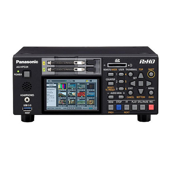
Operating Instructions
Memory Card Portable Recorder
Model No.
Model No.
Vol.1
ENGLISH
VQT3S21
Advertisement
Chapters
Table of Contents

Related Manuals for Panasonic AG-HPD24PJ


Summary of Contents for Panasonic AG-HPD24PJ
- Page 1 ■ This product is eligible for the P2HD 5 Year Warranty Repair Program. For details, Operating Instructions Vol.1 see page 90 of Vol.2. Memory Card Portable Recorder Model No. Model No. Volume Note that Operation Instructions Vol.1 describes basic operations of the Memory Card Portable Recorder.
-
Page 2: Read This First! (For Ag-Hpd24P)
AC plug. liquid containers on top of the equipment. Please contact either a local or foreign Panasonic authorized service center for assistance in selecting an alternate AC plug. WARNING: Always keep memory cards (optional accessory) CAUTION: out of the reach of babies and small children. -
Page 3: Declaration Of Conformity
Please call 1-800-8-BATTERY for information on how to recycle this battery. Notice (U.S.A. only): Disposal may be regulated in your community due to Environmental considerations. For disposal or recycling information, please visit Panasonic website: http://www.panasonic.com/environmental or call 1-888-769-0149. Note: Recorder The rating plate is on the underside of the recorder. - Page 4 Read this first! (For AG-HPD24P) (continued) Brazil Only Brasil Apenas ■ Manuseio de baterias usadas BRASIL Após o uso, as pilhas e /ou baterias poderão ser entregues ao estabelecimento comercial ou rede de assistência técnica autorizada. Cobrir os terminais positivo (+) e negativo (-) com uma fita isolante adesiva, antes de depositar numa caixa destinada para o recolhimento.
-
Page 5: Important Safety Instructions
Read this first! (For AG-HPD24P) (continued) IMPORTANT SAFETY INSTRUCTIONS 1) Read these instructions. 2) Keep these instructions. 3) Heed all warnings. 4) Follow all instructions. 5) Do not use this apparatus near water. 6) Clean only with dry cloth. 7) Do not block any ventilation openings. Install in accordance with the manufacturer’s instructions. 8) Do not install near any heat sources such as radiators, heat registers, stoves, or other apparatus (including amplifiers) that produce heat. -
Page 6: Read This First! (For Ag-Hpd24E)
Read this first! (For AG-HPD24E) indicates safety information. WARNING: CAUTION: This equipment must be earthed. Do not remove panel covers by unscrewing To ensure safe operation, the three-pin plug them. must be inserted only into a standard three- To reduce the risk of electric shock, do not pin power point which is effectively earthed remove the covers. -
Page 7: Caution For Ac Mains Lead
If you lose the fuse cover the plug must not be Fuse used until a replacement cover is obtained. A replacement fuse cover can be purchased from your local Panasonic Dealer. - Page 8 If you lose the fuse cover the plug must not be Fuse used until a replacement cover is obtained. A replacement fuse cover can be purchased from your local Panasonic Dealer.
- Page 9 4. Connect the apparatus to another power outlet where the power is not shared by any other appliances. Pursuant to at the directive 2004/108/EC, article 9(2) Panasonic Testing Centre Panasonic Service Europe, a division of Panasonic Marketing Europe GmbH Winsbergring 15, 22525 Hamburg, F.R. Germany...
-
Page 10: Read This First! (For Ag-Hpd24P/Ag-Hpd24E)
Panasonic products and batteries manufactured by other companies and certified by Panasonic. (Batteries which do not support this function cannot be used). Panasonic cannot in any way guarantee the quality, performance or safety of batteries which have been manufactured by other companies and are not genuine Panasonic products. - Page 11 • Orange button labels indicate alternate functions enabled by holding the SHIFT button. The operating instructions refer to the buttons only by label, without mentioning the SHIFT button. Website URL • URL:http://pro-av.panasonic.net/ About copyrights • Copyright laws may prohibit use, except for personal pleasure, of your recorded video and audio...
-
Page 12: Table Of Contents
Contents Volume 1 Turning Power On and Off ....27 Turning On ..........27 Read this first! (For AG-HPD24P) ..2 Turning Off ..........27 Read this first! (For AG-HPD24E) ..6 About Auto Power Off during operation ... 28 Read this first! (For AG-HPD24P/ Setting the Year, Month, Day and AG-HPD24E) ........ - Page 13 Contents Selecting the 3D REC/PB Mode ..42 Setup Menu ...........52 Turning Power On and Off ....43 Turning On ..........43 Turning Off ..........43 Specifications ........53 Recording and Playback ..... 44 Recording ..........44 Index ............58 Playback ..........45 Displaying 3D Thumbnails ....
-
Page 14: Usage Precautions
• Please understand that Panasonic makes no guarantees for your recordings in cases where • Sand and dust can damage the unit or card. video and/or audio were not recorded as you... -
Page 15: Ac Adaptor
• A temporary afterimage (burn-in) may occur • In a high-temperature and high-humidity when the same image or text is displayed for a location, the LCD panel characteristics may long time, although it can be recovered by change and result in uneven image quality. turning power off for several hours. -
Page 16: Remove The Battery After Use
Remove the battery after use. Completely remove the battery. (The battery continues to be used even if you have turned the unit off.) The battery can over discharge if you leave it in the unit and it may become impossible to recharge it. Before Use Always confirm the year, month, day, time and time zone, and set as necessary... -
Page 17: Supplied Accessories, Optional Accessories
Supplied Accessories, Optional Accessories Supplied Accessories Battery Battery charger / AC power supply cables AG-HPD24P AG-HPD24E (For the U.K.) For part numbers for the battery, see (For areas other “Optional Accessories” than the U.K.) below. 3D connection label AC adaptor / AC power supply cables AG-HPD24P AG-HPD24E (For the U.K.) -
Page 18: Control Reference Guide
Control Reference Guide Controls 10 11 About button labels:Orange labels indicate alternate functions enabled by simultaneously pressing SHIFT. <Example> Press the SHIFT and REMOTE/MODE buttons at the same time to execute the MODE button function. 3D REC/PB REMOTE/MODE button Synchronizes the operation of two units to REMOTE button: record and playback Dual P2 3D clips Enables remote control of the unit via the... - Page 19 SHIFT + +/– buttons (➝ “Displaying thumbnails of clips on storage devices and viewing video on the monitor” RESET/TC PRESET button: Vol. 2, page 33) Resets the CTL counter when displayed. Cursor control buttons When the counter displays TC or UB, presets Up/Down/Left/Right cursor buttons: the time code/user bits.
- Page 20 CANCEL button: STILL/PAUSE button This button cancels a selection or interrupts Press during playback to pause (STILL) and copying. display a still image. Press during recording to toggle recording REW, PREV button standby (PAUSE). REW button: Press to resume recording from standby. Fast rewind during playback.
-
Page 21: Slots, Etc
Slots, etc. POWER lamp P2 card slots (➝ “Turning Power On and Off” page 27) (➝ “Inserting a P2 Card” page 29) POWER button EJECT buttons Press and hold to turn power on and off. (➝ “Inserting a P2 Card” page 29) (➝... -
Page 22: I/O Connectors
I/O Connectors , ➝ page 38 “Synchronous Playback” page TIME CODE IN/OUT Jacks TIME Accepts an external time code ◆ NOTE: CODE IN: for recording onto P2 cards. • The HD reference video signals must be TIME Outputs the playback time positive and negative polarity tri-level sync CODE code during playback. - Page 23 • When recording 720p with an HD control the unit. reference or no reference input, the ◆ NOTE: recorded phase may be shifted from the • Use double-shielded cable for input signal. connections. • When the SETUP - SYSTEM - FREQUENCY menu setting is 59-23 or 60-24, the HD LINK(D) connector reference signal can only synchronize...
-
Page 24: Preparation
Preparation Charging the battery The battery is not charged when the product is • The CHARGE lamp on the charger purchased. Use the steps below to fully charge goes out when charging ends. the battery using the supplied charger. We recommend keeping one spare battery on hand. -
Page 25: Power Preparations
Power Preparations Using a battery Installation Slide in the battery until it clicks into place. Removal POWER lamp Battery latch release button Hold the POWER button for two seconds to turn the power off, and confirm that the POWER lamp is off. Press the battery lock release button to slide out the battery. -
Page 26: Using The Ac Adaptor
Using the AC adaptor Installation Plug the AC adaptor’s AC power supply cable into the adaptor, and then into a power outlet. Connect the AC power supply cable in A-B order. Slide in the DC power supply cable plate until it clicks into place. Insert the plugs all the way in. -
Page 27: Turning Power On And Off
Turning Power On and Off Turning On From the power-off state, hold the POWER button for one second to turn the unit on. When on, the POWER lamp lights green. POWER button POWER lamp ◆ NOTE: The following messages appear during startup. •... -
Page 28: About Auto Power Off During Operation
About Auto Power Off during operation The Auto Power Off function automatically turns the unit off after a short period if no operation such as recording, playback, copying or formatting is performed during that time. To resume operation after Auto Power Off, press the POWER button again. -
Page 29: Basic Operation
Basic Operation About P2 Cards P2 Card Access Lamp and P2 Inserting a P2 Card Card Status P2 Card P2 Card Status Access Lamp Lights green Writing and reading are enabled. Lights orange Writing and reading are enabled for the current recording (including LOOP REC). -
Page 30: About P2 Card Recording Times
• 32 GB, 16 GB and 8 GB P2 cards have Extinguished The P2 card is not formatted recording times of 1/2, 1/4 and 1/8th of that properly. Reformat it in this provided by a 64 GB P2 card, respectively. unit. -
Page 31: Removing P2 Cards
Raise the EJECT button. Removing P2 Cards Press the EJECT button to eject the P2 card. Press the STOP button. If the access lamp of the P2 card to be removed is blinking in orange, you can press the STOP button to stop recording or playback and to abort ongoing operations such as clip copying and deleting or just wait for the operation to finish. -
Page 32: Menu Operations
Menu Operations The menu operations are as follows. Press the SET button. Hold the POWER button for one second to ◆ NOTE: turn the unit on. • Some menu items may display a confirmation dialog. Press the MENU button to open the menu. •... -
Page 33: Lcd Monitor Settings
LCD Monitor Settings Press the MENU button to open the menu. On the SETUP - LCD menu, use the cursor buttons to select an adjustment. Available adjustments are BACKLIGHT, COLOR LEVEL, BRIGHTNESS, and CONTRAST. Press the SET button. Change the selected adjustment value with the Up/Down cursor buttons, and confirm with the SET button. -
Page 34: Thumbnail Screen Display
Thumbnail Screen Display This unit provides a thumbnail screen for managing clips. A “clip” consists of a set of video, audio and additional information such as meta data, and a “shot” is a clip generated by single normal start-to-stop recording operation. A shot that spans multiple P2 cards is handled as a single clip. The thumbnail screen displays a list of thumbnails of recorded clips. -
Page 35: Recording
Recording Hold the POWER button for one second to ◆ NOTE: turn the unit on. • Recording is disabled when the thumbnail In the menu, select the frequency, format and screen is open. Close the thumbnail screen input signal to be recorded, as necessary. before starting to record. -
Page 36: Time Code, User Bits And Ctl
Time Code, User Bits and CTL Time Code The time code is the recorded signal output from the time code generator. The time code can be displayed on the LCD or superimposed on the video. TCR 00 : 07 : 04 : 24 HH MM SS Frame User Bits “User Bits”... -
Page 37: External Connections
External Connections USB Device A P2 card in this unit’s P2 card slot can be accessed as a mass storage device by connecting the unit to a PC using USB 2.0. In this case, the PC must have a driver installed (for USB 2.0). Clips recorded on P2 cards can also be viewed on a PC using our free P2 Viewer, downloadable from our website ➝... -
Page 38: 3D Signal Recording And Playback
3D Signal Recording and Playback Connect two AG-HPD24 units and press the MODE button to select the 3D recording and playback mode (3D REC/PB), for dual P2 3D recording on a pair of P2 cards. Dual P2 3D clips recorded in the 3D REC/PB mode can be played back in 3D. -
Page 39: Connections
Connections Recording Connection Example AG-HPD24 (Master/3D-L) HD-SDI (Left eye image) AG-3DA1 or equivalent ASync Signal BLINK (USB) C LINK (D-SUB) An input reference signal can be connected to the REF IN jack on the slave. HD-SDI (Right eye image) AG-HPD24 (Slave/3D-R) Connect the master and slave units as illustrated. -
Page 40: Playback Connection Example
Playback Connection Example When connecting a 3D monitor for viewing 3D OUTPUT SDI OUT Jack HDMI OUT video, select the signal connector and format to Port suit the monitor type or display method. The unit’s DISCRETE Discrete left and No output output connector and signal format are selected L / R right output... - Page 41 Master Slave Remarks (L) Jack (R) Jack A REF IN VIDEO BNC cable B LINK (M) LINK (S) USB 2.0 cable Type A Type B C LINK (D) LINK (D) RS-422A- 9P D-SUB 9P D-SUB compliant cable, Length 1 m or less D SDI IN SDI OUT BNC cable...
-
Page 42: Selecting The 3D Rec/Pb Mode
Selecting the 3D REC/PB Mode • If a LINK cable is not connected, the “WAITING Connect two units with the appropriate FOR CONNECTION” state occurs. cables according to the connection (➝ “Warning information displayed in 3D examples. REC/PB mode and SYNC PB mode” Vol. 2, ◆... -
Page 43: Turning Power On And Off
Turning Power On and Off Turning On Turning Off From the power-off state, hold the POWER button From the power-on state, hold the POWER button for one second to turn the unit on. for two seconds to turn the unit off. When on, the POWER lamp lights green. -
Page 44: Recording And Playback
Recording and Playback When the 3D REC/PB mode is enabled, all operations are performed from the master unit. Slave unit operations are disabled. Recording Insert P2 cards in the corresponding slots Master/Slave Unit in both master and slave units. ◆ NOTE: •... -
Page 45: Playback
Playback from the Thumbnail Screen Playback Pressing the PLAY button starts playback from SDI and HDMI 3D video playback output is the yellow-framed clip (selected by the cursor available only during PLAY and STILL/PAUSE. buttons). On the thumbnail screen, clip playback •... -
Page 46: Displaying 3D Thumbnails
Displaying 3D Thumbnails 3D thumbnails can be displayed in the same way as normal thumbnails. Displaying the Thumbnail Screen Turn both master and slave units on by Press the THUMBNAIL button. holding each unit’s POWER button for one The thumbnails are displayed. Press the THUMBNAIL button again to close second. - Page 47 Battery level indicator Indicates the remaining charge in the master unit’s battery. ◆ NOTE: • The remaining charge in the slave unit’s battery is displayed on the slave. Dual P2 3D clip fault indicator This is displayed when there is a problem with a Dual 3D P2 clip, such as reversed left-right card insertion.
-
Page 48: Synchronous Playback
Synchronous Playback Left/right 3D clip pairs not recorded in dual P2 3D mode can be played back using the synchronous playback (SYNC PB) mode. Connect two AG-HPD24 units in the same way as for 3D REC/PB mode, and press the MODE button to select the SYNC PB mode for synchronous video playback operation of the slave with the master unit. -
Page 49: Playback
Vol. 2, page 83) ◆ NOTE: • An error occurs when the connected units • The SYNC PB mode selection is preserved are not the same model and version. internally when power is turned off, and • If you inadvertently switch to the SYNC PB resumes when power is turned back on. -
Page 50: Playback From The Playback Screen (Thumbnail Screen Off)
stopping, select the clips to be paired on the ◆ NOTE: thumbnail screen and press PLAY or STILL/ • When stopped, no image (black screen) is PAUSE to synchronize the clips correctly. displayed. • Signal output is as follows. Playback from the Playback Discrete left and right output method: Screen (Thumbnail Screen Off) Special playback video and video when... -
Page 51: Playback From The Thumbnail Screen
Playback from the Thumbnail Screen ◆ NOTE: Master Unit • When the clip time codes are different, incorrect synchronization prevents correct playback. • When the first position of the master clip is earlier than that of the slave, the master is cued to the first position of the slave. -
Page 52: Setup Menu
Setup Menu THUMBNAIL......Thumbnail display selection settings Vol. 2, page 50 OPERATION......Operations such as formatting Vol. 2, page 51 PROPERTY......Displays clip properties Vol. 2, page 53 META DATA ......Meta data setting and display Vol. 2, page 54 STORAGE ...... -
Page 53: Specifications
Specifications General Operating voltage: 7.2 V DC / 7.9 V DC Power consumption: 19.8 W indicates safety information. Ambient operating temperature: 0 °C to 40 °C Ambient operating humidity: 10 % to 80 % (non-condensating) Ambient storage temperature: –20 °C to 50 °C (–4 °F to 122 °F) Mass: 2 kg (4.41 lb) (without battery) 2.3 kg (5.07 lb) (with supplied battery) - Page 54 Recording times: Card Recording format AVC-Intra 100/ AVC-Intra 50/ DVCPRO/DV DVCPRO HD DVCPRO50 8 GB × 1 Approx. 8 min. Approx. 16 min. Approx. 32 min. 16 GB × 1 Approx. 16 min. Approx. 32 min. Approx. 64 min. 32 GB × 1 Approx. 32 min. Approx. 64 min. Approx.
- Page 55 Resolution: AVC-Intra 100: 1920 × 1080 (1080/59.94i, 1080/50i) 1280 × 720 (720/59.94p, 720/50p) AVC-Intra 50: 1440 × 1080 (1080/59.94i, 1080/50i) 960 × 720 (720/59.94p, 720/50p) VIDEO INPUT Reference input: BNC × 1, Auto switching of black burst / HD 3-value sync SDI input: BNC ×...
- Page 56 AUDIO DIGITAL AUDIO Sampling frequency: 48 kHz (synchronized with video) Quantization: 16 bits (DVCPRO HD/DVCPRO50/DVCPRO/DV) 16/24 bits selectabgle (AVC-Intra 100/AVC-Intra 50) Headroom: 12/18/20 dB (selectable) De-emphasis: T1=50 µs, T2=15 µs (auto on/off) AUDIO INPUT Analog inputs (CH1, CH2): XLR × 2 SDI input: BNC ×...
- Page 57 AC ADAPTOR Rated input: 100 – 240 V AC, 50 Hz – 60 Hz, 0.55 A Rated output: 7.9 V DC, 2.53 A indicates safety information. Dimensions (W × H × D): 42 mm × 31 mm × 104 mm (1-5/8 inches ×...
-
Page 58: Index
Index ■ Number CC (F2) BLANK ..........64 CC REC ............64 25M REC CH ............ 72 CH1 INPUT LEVEL ..........66 3D connection label ......... 17 CH2 INPUT LEVEL ..........66 “3D” Logo ..........46, 37 CHANGE PARTITION NAME ......52 3D REC/PB ............ - Page 59 Duration ............10 INPUT SEL ..........63, 66 DVCPRO HD ..........78, 79 INT SG .............. 63 DVCPRO50 / DVCPRO DV ....... 79 Internal mode ........... 47 Internal speaker ..........56 ■ Items to be displayed as properties ....14 EDH(SD) ............
- Page 60 Partition or folder ..........32 SAVE AS ............74 PB POSITION ........... 57 SD analog composite output ......55 PLAY button ............20 SD Mode ............30 PLAY DELAY ............ 61 SD serial digital ..........55 Playback ......35, 45, 49, 8, 14, 41 SD/SDHC memory card slot ......
- Page 61 THUMBNAIL button ......... 19 Warning information displayed in SYNC PB Thumbnail Editing ........22, 39 mode ............89 Thumbnail Screen ..34, 45, 46, 51, 5, 10, 37 Warning information for unit status ....85 Thumbnail scroll bar ........12 Waveform Monitor (WFM) Display ....
- Page 63 Information for Users on Collection and Disposal of Old Equipment and used Batteries These symbols on the products, packaging, and/or accompanying documents mean that used electrical and electronic products and batteries should not be mixed with general household waste. For proper treatment, recovery and recycling of old products and used batteries, please take them to applicable collection points, in accordance with your national legislation and the Directives 2002/96/EC and 2006/66/EC.
- Page 64 ■ This product is eligible for the Operating Instructions Vol.2 P2HD 5 Year Warranty Repair Program. For details, see page 90. Memory Card Portable Recorder Model No. Model No. Volume Note that Operation Instructions Vol.2 describes advanced operations of the Memory Card Portable Recorder. For instructions on basic operations of the Memory Card Portable Recorder, refer to Operating Instructions Vol.1 (printed documents) supplied with the unit.
- Page 65 • Orange button labels indicate alternate functions enabled by holding the SHIFT button. The operating instructions refer to the buttons only by label, without mentioning the Shift button. Website URL • URL: http://pro-av.panasonic.net/ About copyrights • Copyright laws may prohibit use, except for personal pleasure, of your recorded video and audio content without permission of the...
- Page 66 Contents Volume 1 Read this first! (For AG-HPD24P) Power Preparations Read this first! (For AG-HPD24E) Basic Operation Read this first! External Connections (For AG-HPD24P/AG-HPD24E) 3D Signal Recording and Playback Usage Precautions Synchronous Playback Supplied Accessories, Optional Setup Menu Accessories Specifications Control Reference Guide Index Preparation...
- Page 67 Contents Using a Keyboard .......... 80 Full Keyboard ............80 Numeric Keyboard ............ 80 USB Keyboard ............81 For Long and Trouble-Free Operation... 82 Maintenance ............82 Condensation ............. 82 Storage Precautions ........... 82 Warning and Error Messages ......83 Error Information ............
-
Page 68: Available Modes
Available Modes This unit comes with four modes: Main mode, USB device mode, 3D recording/playback mode and synchronous playback mode. Press the MODE button to select or change modes in the menu that appears. Each mode enables access to the “thumbnail screen” for displaying, managing and playing back clip thumbnails and the “recording/playback screen”... -
Page 69: Main Mode
Main Mode Recording/Playback Screen ■ Adjusting the recording volume Use the recording/playback screen for the following. • Playing back all cards in the order they were recorded The level meters show CH1 and CH2 recording volume when • Recording to P2 cards you press the REC VOLUME button (assigned to a USER button) while the menu setting SETUP - AUDIO - INPUT SEL is set to analog audio input. - Page 70 Terminating Loop Recording Mode Various types of recording Use one of the following two methods. • Hold down the POWER button for 2 seconds to turn the unit ■ Hot Swap Recording off. With a P2 card in both card slots it is possible to make one •...
-
Page 71: Playing Back Clips
Press the Left/Right cursor buttons during playback Playing Back Clips or STILL. Playback changes to high-speed or slow and indicated as SHTL +/– speed. Playback Press the Left/Right cursor buttons to change Before you can start recording, you have to set the playback playback speed. -
Page 72: Repeat Playback
Clip and text forward/rewind Engage playback, still or other image display mode. Press PREV or NEXT. The clip beginning or text memo position that is located depends on the value set choosing the SETUP - BASIC - SEEK POS SEL menu setting. (➝ Setup Menu “BASIC” - “SEEK POS SEL”... -
Page 73: Thumbnail Screen
Thumbnail Screen The thumbnail screen enables the following functions: ◆ NOTE: • Displays clip thumbnails, information, P2 card status and • Recording cannot start from the thumbnail screen or from playback other data of a thumbnail screen. To record, press the THUMBNAIL button to •... - Page 74 Selected number of clips possible, format the P2 card. Instead of appears to indicate that a clip is not Indicates the number of selected clips and the total in the P2 standard format. number of clips. Indication of P2 card slot and storage device status Time display The status of P2 card and storage device connections One of the following data is displayed: the TC (time...
-
Page 75: Changing Thumbnail Display
◆ NOTE: Setting thumbnails and other OSD display • When there are more characters than can be displayed, output only the range of characters that can be displayed appear. Thumbnail scroll bar Indicates the location of the currently displayed thumbnail among displayed thumbnails. Battery status indicator Displays the following icons to indicate remaining battery charge. - Page 76 Press the SET button. Setting thumbnail size Press the MENU button to end processing. Setting order of date indication Use the steps below to change the order of year, month and day in date indications. Open the thumbnail screen. Press the MENU button. Use the Up/Down/Left/Right cursor buttons to choose the SETUP - THUMBNAIL - THUMBNAIL SIZE menu setting and select the size of clips you...
-
Page 77: Playing Back Clips
Selecting items to be displayed as Playing back Clips properties Select items that will appear in a simplified property display on Playback the left side of the thumbnail. Open the thumbnail screen. Open the thumbnail screen. Press the MENU button. Move the Up/Down/Left/Right cursor buttons to the clip you want to play back. -
Page 78: Playing Back Single Clips
• When playback stops, the cursor moves to the clip played prior Playing back from text memo location to stopping. • Video and audio playback may be disrupted between clips in different video formats (1080i, 720p) or compression formats (DVCPRO HD, DVCPRO50, DVCPRO, DV, AVC-Intra 50 and AVC-Intra 100). -
Page 79: Selecting And Deselecting Clips
When the cursor is in the lower half of the monitor, Press the SET button. use the Left/Right cursor buttons to select the A blue frame appears on the clip selected with the cursor to indicate that it is selected. thumbnail with the text memo you want to play and press the PLAY button. -
Page 80: Attaching Text Memos
Attaching text memos When a text memo is added, you can open a thumbnail at the text memo location for playback or copying and seek (move) text memo location by pressing the NEXT/PREV button during video playback. (➝ Setup Menu “BASIC” page 59) Change the thumbnail screen to the text memo display. -
Page 81: Copying Clips
Each press of this button turns the shot mark indicator on This starts copying. and off. ◆ NOTE: • A shot mark is added to a clip even if the button is pressed in the record/playback screen. • When attaching or deleting shot marks for clips that span multiple P2 cards, be sure to load all the P2 cards that the clip is recorded on. -
Page 82: Reconnecting Incomplete Clips
Select the clip to delete. appears and press the SET button. Select NO when you do not want to repair the clip. Press the MENU button. ◆ NOTE: • Some clips are so badly damaged they cannot be repaired. Use the Up/Down/Left/Right cursor buttons to Such clips are indicated by a red choose the OPERATION - DELETE menu setting and press the SET button. -
Page 83: Viewing And Revising Clip Information
◆ NOTE: ◆ NOTE: • When some but not all the clip segments in a clip that consists • Voice memo/Indicator of three or more clip segments are reconnected, the incomplete Indicates that a voice memo has been attached to a clip. clip indicator ( ) will remain. - Page 84 Use the Up/Down/Left/Right cursor buttons to select ACCESS: The date of the last update and other the meta data you want to revise and press the SET information (CREATOR, CREATION DATE, LAST button. UPDATE DATE, LAST UPDATE Data that can be revised is indicated as “TEXT”, like in the PERSON) illustration below.
-
Page 85: Thumbnail Editing
◆ NOTE: Thumbnail Editing • The THUMBNAIL field in the clip property display shows the change in thumbnail location (number of frames from the Use the following steps to change a thumbnail of video at a start). The number for a normal first thumbnail is 0. location to which a text memo has been attached. - Page 86 Incrementing the counter value of the USER CLIP Setup to attach meta data NAME for clips exceeding 4 GB In the following case, one shot is recorded as multiple clips ■ Preparing for meta data recording and the counter value is automatically incremented and Use this procedure to determine whether or not to attach the recorded for each shot.
- Page 87 ■ Checking and revising loaded meta data Use the Up/Down/Left/Right cursor buttons to choose the META DATA - LOAD menu setting and Use the following steps to check meta data loaded from an SD memory card. press the SET button. Open the thumbnail screen.
-
Page 88: Formatting P2 And Sd Memory Cards
While viewing meta data settings, use the Up/Down/ Formatting P2 and SD Memory Left/Right cursor buttons to move the cursor to the Cards setting you want to change and press the SET button. The on-screen keyboard appears. Make the required changes. -
Page 89: Checking Card Status
Checking Card Status Use the following steps to view P2 card slot status, P2 card usage and other card information on the screen. Open the thumbnail screen. Press the MENU button. Use the Up/Down/Left/Right cursor buttons to choose the PROPERTY - CARD STATUS menu setting and press the SET button. -
Page 90: Connecting An External Device Via The Usb Host Connector
P2 card remaining memory (or memory used)/total The following storage devices can be used. memory • Panasonic portable hard disk unit P2 store (AJ-PCS060G) Indicates P2 card remaining free memory (or memory • Hard disk drives or solid state drives connected via USB used)/total memory in time left in minutes. - Page 91 Storage device types and available functions Available functions depend on the type of storage device used. “PARTITION:” in the left half of the EXPLORE screen provides information on the particular storage device that is connected. (➝ “Viewing storage device information (EXPLORE screen)” page 31) ◆...
- Page 92 • A storage device is a high-precision instrument whose read and write functions may fail if used in an unsuitable environment. Please note that Panasonic accepts no liability whatsoever for data loss or other losses either direct or indirect arising from hard disk damage or other defects.
- Page 93 5,6,7 Connecting a Storage Device Select YES in the confirmation message that A storage device that is not TYPE S or FAT will be appears and press the SET button. formatted as a TYPE S or FAT storage device. (➝ “Formatting storage devices” page 29) When the confirmation message appears again, select YES and press the SET button.
- Page 94 data is not checked. To disable verify, set the STORAGE - SETUP - VERIFY menu setting to OFF. When exporting to a FAT volume, verify is not performed regardless of this setting. • To interrupt exporting, press the SET button, select YES in the CANCEL confirmation that appears and press the SET button again.
- Page 95 Connecting a Storage Device. NUMBER(NO.): Partition number (1 - ) MODEL: P2 card model name Open the thumbnail screen. PARTITION Name assigned to partition NAME: (➝ “Entering a partition name” page 33) DATE / TIME: Date and time of partition recording Press the MENU button.
- Page 96 Enter a name for the partition and select OK. The name is assigned to the partition. Deleting the last partition Choose the OPERATION - DELETE LAST PARTITION menu setting (➝ Setup Menu “OPERATION” - “DELETE LAST PARTITION” page 52) to delete the last partition on a storage device.
- Page 97 NUMBER Folder no. (1 - ) (NO.): DATE / TIME: Date and time of folder created FOLDER: Folder name SIZE / Storage device capacity/remaining capacity FREE CAP.: : Date created is not shown for root. ◆ NOTE: • Use the SHIFT and +/- buttons to move to thumbnail displays on adjacent partitions or folders without returning to the EXPLORE EXIT screen.
- Page 98 Checking audio and video of a clip Insert the P2 card that will store the imported partition. Be sure to insert a formatted P2 card. Connect a storage device. Select the STORAGE - EXPLORE menu setting to open the EXPLORE screen. Display a thumbnail of a partition you want to import in the EXPLORE screen.
-
Page 99: Usb Device Mode
USB Device Mode A USB 2.0 connection with a PC allows you to use P2 cards ◆ NOTE: inserted in the slots on this unit as mass storage. Note that a • Please refer to the operating instructions supplied with your PC separate USB driver (found on the supplied CD-ROM) must and software. -
Page 100: Recording/Playback Mode (3D Rec/Pb)
3D Recording/Playback Mode (3D REC/PB) This chapter describes the 3D recording/playback mode and how to record and playback Dual P2 3D clips. For details on connections, recording and playback operations refer to the following section. (➝ “3D Signal Recording and Playback” Vol. 1, page 38) Displaying and Managing Clips Although display and playback is limited to Dual P2 3D clips, basic operations (in main mode) are the same as for normal clips except for a few restrictions. -
Page 101: Changing Thumbnail Display
Changing Thumbnail Display Adding Text Memos and Shot Marks Like in main mode, you can customize the thumbnail screen Text memos and shot marks can be added like in main mode. to suit operating conditions and improve efficiency. However, additions can only be made to clips on the master (➝... -
Page 102: Viewing And Revising Clip Information
Use the Up/Down/Left/Right cursor buttons to Viewing and Revising Clip choose the OPERATION - FORMAT - ALL P2 menu Information setting and press the SET button. ◆ NOTE: The same operations for viewing and revising clip information • Selecting SD CARD will format an SD memory card inserted in as in main mode are available. - Page 103 Total remaining recording time (or used space) Indicates the remaining capacity available for 3D recording or used space and space available for 3D recording. ◆ NOTE: • The total of minimum card capacity for the master and slave side slots is total capacity, while the total of minimum recording capacity is total remaining recording capacity.
-
Page 104: Synchronous Playback Mode (Sync Pb)
Synchronous Playback Mode (SYNC PB) This chapter describes playback and other operations in synchronous playback mode with two connected AG-HPD24 units. For details on connecting and switching modes, see the following section. (➝ “Synchronous Playback” Vol. 1, page 48) Playback Synchonous playback of clips on 2 units is possible when the following conditions are satisfied. - Page 105 Example 2: The starting point of Clip1 differs (but the length is the same). ➝ Clip1 on the slave side starts after being aligned with the master side start position. In the meantime, L and R video is correctly output from SDI. Since the Clip number or time code differs when the slave Clip 1 playback ends, SDI is muted and turns black.
-
Page 106: Displaying And Managing Clips
Displaying and Managing Clips Operations are performed using the same operations as in setting is set to OFF, video is output only via the SDI output on the master side. main mode. • Side-by-side, frame-packing system: Only video from the master On the slave side, you can check clips by opening the side is output to the LCD and SDI/HDMI (video on the R side is thumbnail screen, but control is restricted to THUMBNAIL,... -
Page 107: Screen Display
Screen Display OSD Display Formats, time codes and modes are indicated by abbreviations in playback and recording screens. ◆ NOTE: • Use the SETUP - DISPLAY - OSD GRADE menu setting to display all (All)/display 1) to 6) only (MODE&TC). Use the SETUP - DISPLAY - OSD TC SELECT menu setting to switch MODE&TC settings. -
Page 108: Deck Information (Diag) Icons
Audio level meter display or recording standby. Indicates the system format of the played clip during Indicates input level during recording or recording standby playback. and audio level of played clip during playback. Indicates value of set monitor volume in the upper rows (4 System frequency indicator and 5) of the audio level meter when the AUDIO MON +/- Indicates the system frequency. -
Page 109: Waveform Monitor (Wfm) Display
Example: • HDSDI is selected for input and 720/59.94p signals are input • The system is 1080/59.94i, DVCPRO HD • SDI is selected for output • Reference signals are not input • The video input reference signal serves as a reference signal for the system Light color indicates unselected items WARNING:... -
Page 110: Time Code, User Bits, Ctl
Time Code, User Bits, CTL Time Code Setting Time Code and User Bits The time code is used when the time code signal generated Internal mode by the time code generator is to be recorded. The time code values are indicated on the display and in the superimpose display. - Page 111 Steps for setting TC/UB: External mode Press the TC PRESET button. The left-most digit starts flashing. Press the Up/Down cursor buttons to change the value. Press the Left/Right cursor buttons to select digits. The selected digits start flashing. The setting ranges are as follows: Time code: [59.94 Hz] 00:00:00:00 - 23:59:59:29...
-
Page 112: Reproducing The Time Code And User Bits
Reproducing the Time Code and User Bits Engage the stop mode. Use the COUNTER button to select TC or UB. Press the PLAY button. Playback starts and the time code appears on the LCD display. “ ” : Field 1, field 3 “... -
Page 113: Setup Menu
Setup Menu Menu items ◆ NOTE: • Take care when setting menu SETUP - DISPLAY - CROSS HATCH to something other than OFF since inputting output signals to a consumer monitor may turn the cross hatch pattern into a simulated image. THUMBNAIL Use this menu to perform thumbnail display settings. -
Page 114: Operation
Mode SYSTEM FREQ Item Settings and brief function description SYNC indications (Main) Displays thumbnails only for clips to which shot marks have been 59.94 Hz 50 Hz attached. MARKED 23.98 Hz 24 Hz CLIPS 59-23 Hz 60-24 Hz Displays thumbnails only for clips with text memo data. 59.94 Hz 50 Hz TEXT MEMO... - Page 115 Mode SYSTEM FREQ Item Settings and brief function description SYNC indications (Main) Restores clips that have been damaged by sudden power outages 59.94 Hz 50 Hz during recording or by other causes and are marked by the bad clip 23.98 Hz 24 Hz indicator (yellow REPAIR CLIP...
-
Page 116: Property
PROPERTY Use this menu to display detailed information of clips and cards and perform display settings. MENU THUMBNAIL OPERATION PROPERTY META DATA STORAGE SETUP FILE SYSTEM INFO Mode Settings and brief function description SYSTEM FREQ Item SYNC XX indicates factory default settings. indications (Main) Displays detailed clip information on the screen. -
Page 117: Meta Data
META DATA Use this menu to set meta data. MENU THUMBNAIL OPERATION PROPERTY META DATA STORAGE SETUP FILE SYSTEM INFO Mode Settings and brief function description SYSTEM FREQ Item SYNC XX indicates factory default settings. indications (Main) Loads the meta data upload file saved on an SD memory card. 59.94 Hz 50 Hz LOAD... -
Page 118: Storage
STORAGE Use this menu to set up storage devices and switch display of information. MENU THUMBNAIL OPERATION PROPERTY META DATA STORAGE SETUP FILE SYSTEM INFO Mode Settings and brief function description SYSTEM FREQ Item SYNC XX indicates factory default settings. indications (Main) Exports (writes) data by card from a P2 card to a storage device. -
Page 119: Setup
SETUP Use these menus to set up unit operations. MENU THUMBNAIL OPERATION PROPERTY META DATA STORAGE SETUP FILE SYSTEM INFO THUMBNAIL Use this menu to make thumbnail settings. Mode Settings and brief function description SYSTEM FREQ Item XX indicates factory default settings. indications SYNC PB (Main) - Page 120 Mode Settings and brief function description SYSTEM FREQ Item XX indicates factory default settings. indications SYNC PB (Main) Select the format for indicating the time. 59.94 Hz 50 Hz Y - M - D: Year/month/day 23.98 Hz 24 Hz M - D - Y: Month/day/year (AG-HPD24P dafault value) D - M - Y: Day/month/year (AG-HPD24E dafault value) 59-23 Hz 60-24 Hz...
- Page 121 Mode Settings and brief function description SYSTEM FREQ Item XX indicates factory default settings. indications SYNC PB (Main) Specifies the items that will appear in a simplified property display 59.94 Hz 50 Hz on the left side of the thumbnail. 23.98 Hz 24 Hz USER CLIP NAME: Indicates the name of a user clip...
- Page 122 REMOTE mode, AREC appears in a superimposed screen. • Set the REMOTE mode. • For details on TYPE1 or TYPE2, refer to “Panasonic camera- recorders, recording format and record start/stop signals (Recording Mark)” (page 61). • To start automatic recording, press the REC and STILL buttons simultaneously to place this unit in REC PAUSE mode.
- Page 123 Mode Settings and brief function description SYSTEM FREQ Item XX indicates factory default settings. indications SYNC PB (Main) Select reference for video output. 59.94 Hz 50 Hz AUTO: Uses the reference signal input to the REF connector as reference. When there is not input to the REF connector, the selected video input signal is used as reference.
- Page 124 BEEP NOTE: 59-23 Hz 60-24 Hz • A beep sound is also output from the ANALOG AUDIO MON output connectors. Panasonic camera-recorders, recording format and record start/stop signals (Recording Mark) Model Recording format Recording Mark TYPE Remarks AJ-HDC27F, H 720 / **p over 60p 720 / 59.94p...
- Page 125 TC/UB/CTL Use this menu to set the time code. Mode Settings and brief function description SYSTEM FREQ Item XX indicates factory default settings. indications SYNC PB (Main) Selects 12 or 24 hour clock for the CTL counter display. 59.94 Hz 50 Hz ±12h: 12-hour clock display CTL DISPLAY...
- Page 126 Mode Settings and brief function description SYSTEM FREQ Item XX indicates factory default settings. indications SYNC PB (Main) Specifies an operating mode that advances the internal time code 59.94 Hz 50 Hz generator. 23.98 Hz 24 Hz REC RUN: The internal time code generator is advanced only during recording.
- Page 127 Mode Settings and brief function description SYSTEM FREQ Item XX indicates factory default settings. indications SYNC PB (Main) Turns on and off closed caption signals in the first field output from 59.94 Hz the SD SDI and analog composite output. BLANK: Signals are forcibly blanked.
- Page 128 Mode Settings and brief function description SYSTEM FREQ Item XX indicates factory default settings. indications SYNC PB (Main) Specifies the video signal output from the video output connector. 59.94 Hz 50 Hz When 59.94 Hz is set AUTO: Switches output automatically depending on current recording and playback format.
- Page 129 Mode Settings and brief function description SYSTEM FREQ Item XX indicates factory default settings. indications SYNC PB (Main) Selects gamma correction. 59.94 Hz 50 Hz GAMMA1: Corrects video shot by Varicam or in the FILM REC 23.98 Hz 24 Hz mode on an AJ-HPX3000 to film-quality video.
- Page 130 Mode Settings and brief function description SYSTEM FREQ Item XX indicates factory default settings. indications SYNC PB (Main) Selects the standard level. 59.94 Hz 50 Hz FS-20: -20 dB (AG-HPD24P default value) REF LEVEL 23.98 Hz 24 Hz FS-18: -18 dB (AG-HPD24E default value) 59-23 Hz 60-24 Hz FS-12: -12 dB...
- Page 131 Mode Settings and brief function description SYSTEM FREQ Item XX indicates factory default settings. indications SYNC PB (Main) Specifies the superimposed text. 59.94 Hz 50 Hz Here, data indicates the CTL/TC/UB value selected with the 23.98 Hz 24 Hz COUNTER button. TIME: Data 59-23 Hz 60-24 Hz...
- Page 132 Use this menu to make LCD settings. Mode Settings and brief function description SYSTEM FREQ Item XX indicates factory default settings. indications SYNC PB (Main) Use the settings below to have the LCD monitor automatically turn 59.94 Hz 50 Hz off after a specified time (5 min) of inactivity.
-
Page 133: User Button
USER BUTTON Use this menu to assign specific functions set in menus to the USER1 - USER6 buttons. The settings are stored internally and persist even when the unit is turned off and on. Assigned functions and settings can be confirmed in the DIAG display. Mode Settings and brief function description SYSTEM FREQ... - Page 134 Mode Settings and brief function description SYSTEM FREQ Item XX indicates factory default settings. indications SYNC PB (Main) OSD GRADE: Changes MENU - SETUP - DISPLAY - OSD GRADE settings. WFM TYPE: Changes MENU - SETUP - DISPLAY - WFM TYPE settings.
- Page 135 Mode Settings and brief function description SYSTEM FREQ Item XX indicates factory default settings. indications SYNC PB (Main) Specifies the recording/system format used by this unit. 59.94 Hz 50 Hz 1080i (1080p): 1080i mode (when 59.94 Hz or 50 Hz is set)/ 23.98 Hz 24 Hz 1080p mode (when 59-23 is set)
- Page 136 Mode Settings and brief function description SYSTEM FREQ Item XX indicates factory default settings. indications SYNC PB (Main) Adjusts system phase of analog composite output and SD SDI 59.94 Hz 50 Hz output (in 37 ns steps). 23.98 Hz 59-23 Hz SYS H(SD) 1728 - 0 - -1728 -: Is advanced...
-
Page 137: File
FILE Use this menu to write menu settings to or load from SD memory cards. You can also return menu settings to their factory defaults. MENU THUMBNAIL OPERATION PROPERTY META DATA STORAGE SETUP FILE SYSTEM INFO Mode SYSTEM FREQ Item Settings and brief function description indications SYNC PB... - Page 138 Mode SYSTEM FREQ Item Settings and brief function description indications SYNC PB (Main) Returns menu settings to their factory defaults. 59.94 Hz 50 Hz ALL: All the data in the menu 23.98 Hz 24 Hz W/O SYSTEM: Items other than SETUP - SYSTEM INITIAL MENU NOTE: 59-23 Hz...
- Page 139 LOAD SAVE Open MENU. Select MENU. Insert an SD memory card and select menu FILE - LOAD Insert an SD memory card and select menu item to save to select the item to load. from FILE - SAVE AS. Select ALL (all item data) or W O SYSTEM (other than Select ALL (all item data) or W O SYSTEM (data other than...
-
Page 140: System Info
SYSTEM INFO Use this menu to view the system information. MENU THUMBNAIL OPERATION PROPERTY META DATA STORAGE SETUP FILE SYSTEM INFO This menu cannot be opened during recording playback or from HDD EXPLORE. Mode SYSTEM FREQ Item Settings and brief function description indications SYNC PB (Main) -
Page 141: List Of Compatible Input And Output Formats
List of Compatible Input and Output Formats Use menu FREQUENCY, REC FORMAT to select the input /output formats listed below. Recording format Input signal System frequency SDI output 1080 / 59.94i 1080 / 59.94i 59.94 720 / 59.94P 480 / 59.94i 1080 / 50i 1080 / 50i 720 / 50P... - Page 142 Recording format Input signal System frequency SDI output 1080 / 29.97PsF 1080 / 29.97PsF 59.94 720 / 59.94P 480 / 59.94i 1080 / 23.98PsF 1080 / 59.94i 1080 / 23.98P over 59.94i 59.94 720 / 59.94P 480 / 59.94i 1080 / 23.98PsF 1080 / 24PsF DVCPRO HD 1080 / 25PsF...
-
Page 143: Using A Keyboard
Using a Keyboard Full Keyboard Numeric Keyboard The full keyboard appears when meta data input or other Use the numeric keyboard when you need to enter only English input is required. numbers. Move the cursor to the character you want to enter and press Move the cursor to the figure you want to enter and press the the SET button. -
Page 144: Usb Keyboard
USB Keyboard To use a USB keyboard for input, connect it to the KEYBOARD connector when a menu that displays a full keyboard or numeric keyboard is selected. The type of keyboard must first be set in a menu. (➝ Setup Menu “THUMBNAIL” - “KEYBOARD” page 58) If required, use the steps below to set the type of keyboard you want to use. -
Page 145: For Long And Trouble-Free Operation
For Long and Trouble-Free Operation Maintenance Do not use benzene or thinner for cleaning. • Benzene and thinner could deform the unit and cause the paint to peel off. • Disconnect the battery or the power cord from the wall outlet before cleaning. •... -
Page 146: Warning And Error Messages
Warning and Error Messages When the unit generates a warning, the OSD of the record and playback screen shows an error number and an error message. When an operational malfunction occurs in the unit, an error number will flash on the OSD of the record and playback screen. Error Information The POWER lamp, the P2 card access lamp and a beep sound notify the operator of a malfunction that is detected during powering up or operation. -
Page 147: Detailed Warning And Error Information
Detailed Warning and Error Information Display of information on operational warnings • The OSD displays messages when warnings or errors occur. Monitor display Description Deck operation Displayed when data cannot be recorded on a P2 card. [Meaning] • The card is write protected. •... - Page 148 Display of warning information for unit status When there is a problem with unit status, a warning error “E-**” appears in the OSD display. Press the DIAG button to get detailed error information. Display Description Deck operation Character code Displayed for 3 seconds when reduced storage device performance or other cause Operation STORAGE INTERMITTENT has resulted in a dropout during clip playback.
- Page 149 Display Description Deck operation Character code The directory configuration is incorrect. Immediately back up card data and format Operation DIR NG CARD< > the card before using it again.( indicates the slot number where the error continues occurred.) The card has been rewritten the maximum number of times. Replace the P2 card. Operation RUNDOWN CARD<...
- Page 150 Display of thumbnail warning information The following warning messages appear when an incorrect operation is attempted in a thumbnail. Item Message Description Measure Data cannot be accessed because it is CANNOT ACCESS! Restore media and clips to normal state before access. corrupted or for other reasons.
- Page 151 Item Message Description Measure CANNOT ACCESS An error occurred during P2 card access. Check P2 card. CARD! CANNOT ACCESS An error occurred while trying to access the Check storage device status and connections. TARGET! connection target. CANNOT COPY! Clips cannot be copied to a storage device Format using a FAT format or export data from a P2 FORMAT STORAGE TO without partitions.
-
Page 152: Error Information
Warning information displayed in 3D REC/PB mode and SYNC PB mode Message Description Measure ERROR A reference signal has not been connected or the Turn on the slave side and check connection of the REF IN NOT DETECT slave side is not powered up. reference signal line. -
Page 153: Updating The Firmware In This Unit
Such customers can access a special web site to check for updates and download required firmware. Further details on this program are provided by web site listed below, which also handles customer registration. For English: http://panasonic.biz/sav/pass_e/ (2) Customers not registered for a P2HD 5 Year Warranty Repair Program Check firmware version of the unit in the PROPERTY - SYSTEM INFO in the menu. -
Page 154: Handling P2 Card Recording
Handling P2 Card Recording The P2 card is a semiconductor memory card designed for the P2HD series, Panasonic’s line of professional video and broadcast equipment. ■ Since the P2 format records data as files, it is ideally Drive: \ suited for computer processing. Video and audio are... -
Page 155: Use Of Sd/Sdhc Memory Cards
16 GB 32 GB Use of Panasonic SD, SDHC, mini SD, mini SDHC, microSD and microSDHC cards is recommended. • The latest information on the unit and supported memory cards is provided at our P2 Support Web site. For details on the URL (➝ “Website URL” page 2) -
Page 156: Index
Index ■ Number CC (F1) BLANK ..............CC (F2) BLANK ..............25M REC CH ............... CC REC ................. 3D connection label ............46, 37 CH1 INPUT LEVEL ............. “3D” Logo ..............CH2 INPUT LEVEL ............. 3D REC/PB ................CHANGE PARTITION NAME ......... - Page 157 Dividing clips ............... Information added to clips ..........DOWNCONV. MODE ............Information on operational warnings ......Dual P2 3D Clip ..............INITIAL MENU ..............Dual P2 3D clip fault indicator ........INITIALIZE ................Duration ................. INPUT SEL ..............63, 66 DVCPRO HD ..............
- Page 158 ■ P2 Card Recording ............P2 card slot ................SAME FORMAT CLIPS ............. P2 card slots ................ 54, 56 Sampling frequency ..........29, 39 P2 Cards ............... SAVE ..................Partition or folder ..............SAVE AS ................PB POSITION ..............SD analog composite output .........
- Page 159 Text memo indicator ............VITC BLANK ................. Text memo location ............VITC POS-1 ................Text Memos ..............16, 38 VITC POS-2 ................Thumbnail ............ 11, 20, 50, 56 ■ Thumbnail attributes ............Warning information displayed in 3D REC/PB THUMBNAIL button ............
- Page 161 Information for Users on Collection and Disposal of Old Equipment and used Batteries These symbols on the products, packaging, and/or accompanying documents mean that used electrical and electronic products and batteries should not be mixed with general household waste. For proper treatment, recovery and recycling of old products and used batteries, please take them to applicable collection points, in accordance with your national legislation and the Directives 2002/96/EC and 2006/66/EC.