Husqvarna K 760 Workshop Manual
Hide thumbs
Also See for K 760:
- Operator's manual (32 pages) ,
- Price list (48 pages) ,
- Operator's manual (28 pages)
Table of Contents
Advertisement
Advertisement
Table of Contents

Related Manuals for Husqvarna K 760


Summary of Contents for Husqvarna K 760
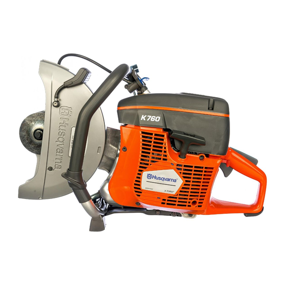
- Page 1 Workshop manual K 760 & K 760 Cut-n-Break HUSQVARNA CONSTRUCTION PRODUCTS...
-
Page 2: Table Of Contents
6. IGNITION SYSTEM 7. FLYWHEEL 8. AIR FILTER 9. FUEL SYSTEM 10. CARBURETTOR 11. DECOMPRESSION VALVE 12. CYLINDER/PISTON 13. CRANKCASE 14. CLUTCH 15. CUTTING HEAD 16. WET SYSTEM 17. HANDLE 18. OILGUARD (OPTIONAL) 19. K 760 CUT-N-BREAK 20. TOOLS 115 32 40-26... - Page 3 This arrangement means that as a mechanic, Workshop manual at least until you have learnt the basic composi- K 760 & K 760 Cut-n-Break tion of the machine, you need to start with the HUSQVARNA CONSTRUCTION PRODUCTS chapter “Dismantling into Basic Modules” to then move on to the chapter covering the speci- “Dismantling into Basic Modules”...
-
Page 4: Special Functional Components
SPECIAL FUNCTIONAL COMPONENTS X-Torq ® This engine technology was introduced with its predecessor K750 under the name Dual Charge, now renamed to X-Torq. In addition to the intake from the carbu- rettor with fuel/air mix there are two chan- nels for intake of fresh air; the upper chan- nels as shown in the illustration. -
Page 5: Components - Orientation
COMPONENTS – ORIENTATION Components 1. Cutting blade 2. Blade guard 3. Handle for the blade guard 4. Front handle 5. Air filter cover 6. Cylinder cover 7. Starter handle 8. Starter 9. Combination spanner 10. Belt adjustment screw 11. Lock screws for belt adjustment 12. -
Page 6: Dismantling Into Basic Modules
DISMANTLING INTO BASIC MODULES Basic modules This chapter shows how the machine is built up of basic modules, for example, the starter, carburettor, air filter system, etc. The purpose is to illustrate how you can easily and effectively dismantle and assemble the machine in its basic modules. - Page 7 DISMANTLING INTO BASIC MODULES Air filter 1. Loosen the guard's three screws and remove the guard. 2. Loosen the two screws that hold the filter bottom. 3. Lift up the filter bottom together with the filter. 4. Press the filter out of the filter bottom. Cylinder cover 1.
- Page 8 DISMANTLING INTO BASIC MODULES Assembly 5. Hook the throttle rod into the valve arm as illustrated. Lift the carburettor unit into position and fit the fuel hose. Press down the throttle rod into throttle control with the help of a pair of pliers. 6.
- Page 9 DISMANTLING INTO BASIC MODULES 3.2. Dismantle the three screws on the air duct cover. 3.3. Lift off the air duct cover. Muffler Dismantle the cutting head and the starter. 1. Dismantle the four screws on the muffler. 2. Dismantle the muffler. Fit the gaskets correctly! 3.
-
Page 10: Starter
STARTER Replacing the starter cord Dismantle the starter. Eliminate the spring force from the return spring 1. Pull out the starter cord approximately 12 in./30 cm. Hold the starter pulley with your thumb and place the cord in the cut-out on the starter pulley. 2. - Page 11 STARTER Starter pulley First eliminate the spring force as per the previous page. Remove the centre screw and lift off the starter pulley. Clean the surfaces between the starter pulley and the spring cassette. Assembly Lubricate the hub with grease (arrows). Preferably also apply some grease around the starter pulley hub so that the grease seals against the spring cassette.
- Page 12 STARTER Starter pawls Function In principle the starter pawls have two positions that are determined by the centrifugal force generated by the rotation of the flywheel. When the engine is at a standstill the springs push the starter pawls towards the centre, which when starting then grip the starter pulley's metal sleeve.
-
Page 13: Ignition System
It is insensitive to moisture and dirt. The design is point such that the ignition point does not need to readjustment. Husqvarna K760 has integrated overspeed protection in the electronic unit that limits the engine's speed to 9,300 rpm. The ignition system consists of the primary coil (A) and 3�... -
Page 14: Trouble Shooting
IGNITION SYSTEM Trouble shooting Examine the ignition system first when the engine does not start. Check the ignition spark Earth the spark plug against the cylinder by using the spark plug socket to extend the earth cable as the air duct prevents direct earthing. - Page 15 IGNITION SYSTEM Test of short circuit cable and stop switch Try using a measuring instrument or the following simple solution: Connect a battery in series with a test lamp to the short-circuit cable and engine body. Observe the test lamp while testing the function of the stop switch.
-
Page 16: Flywheel
Tool 502 51 49-02 Tool 502 51 49-02 502 51 49-02 The special tool is used to A special tool from Husqvarna is dismantle and assemble the required to dismantle and assemble the flywheel. flywheel. The tool fits virtual all fly - wheels on Husqvarna power cutters. - Page 17 FLYWHEEL Mount the screw press Press off the flywheel Press off the flywheel Lock the outer socket with a wrench and Lock the socket and screw in the screw in the centre screw until the fly- centre screw. wheel releases. Hint: If the flywheel is sitting very firm- ly, you can knock lightly with a hammer on the screw to the flywheel to release.
-
Page 18: Air Filter
AIR FILTER Function Husqvarna Active Air Filtration is a filter system that sig- nificantly improves the K760 model. The improved centrifugal cleaning has now made the previous plastic foam filter obsolete. 1. The centrifugal cleaning is the first step in the air clea- ning of the inlet air. -
Page 19: Fuel System
FUEL SYSTEM Fuel filter Fuel filter Dismantle the filler cap. Dismantle the filler cap and pull out the 502 50 83-01 section holding the filler cap in position Catch the fuel hose with the when fuelling. help of tool 502 50 83-01. Catch the fuel hose with the help of tool 502 50 83-01. - Page 20 FUEL SYSTEM Changing the fuel hose Loosen the cable lug to the stop switch to gain better access to the fuel hose. Remove the hose from the tank at the same time as it is fed down through the hole in the carburettor compartment little by little.
- Page 21 FUEL SYSTEM Non-return valve – functional test Connect the non return valve to pressure tester 501 56 27-01. Note: Never expose the non return valve to a high pressure (compressed air)! Test the non return valve by first blowing in the direction towards the tank. The air should pass without a build up of pressure.
-
Page 22: Carburettor
CARBURETTOR Carburettor unit Carburettor unit Dismantling Dismantling Pull up the service filter and put Pull up the service filter and put it to it to one side so that it is not one side so that it is not damaged. damaged. - Page 23 CARBURETTOR Inlet system Check for leaks For maintenance work on the inlet system, you should look care- fully for any leaks, which would cause dust to be sucked in and shorten the engine's life. Dust inside the seals indicates defective or incorrectly fitted components.
- Page 24 CARBURETTOR Components 1. Throttle valve 2. Air valve 3. Choke valve 4. Pulse line, to the carburettor's pump diaphragm 5. Fuel line 6. Connection to air purge 7. High and low speed jet (set at the factory) 8. Idle screw, speed adjustment 9.
- Page 25 CARBURETTOR Functional test Pressure tester 501 56 27-01 The pressure tester has a pump piston that is operated with one hand. The pressure tester is supplied with an adapter nipple for small sizes. Make the hose connection to the nipple as short as possible, this gives a clearer test result.
- Page 26 CARBURETTOR Metering unit Measurement chamber Note the internal order of the parts when dismantling to avoid reassembling in the wrong order. Gaskets A are identical. Measurement chamber – function The measurement chamber has two chambers: Air chamber (to the cover) and a fuel chamber (to the carburettor body).
- Page 27 CARBURETTOR Pump unit Function The pump diaphragm (A) is driven by pressure variations in the crankcase, which are lead to the top of the pump diaphragm. The fuel underneath the diaphragm is pumped to the valves (B). Back pres- sure from the measurement chamber diaphragm to the needle valve in the measurement chamber regulates the valves' degree of opening and the amount of fuel pumped to the measurement chamber's fuel side.
- Page 28 CARBURETTOR Valve axles Valve axles Check that there is no radial play Leakage from the valve axles results in on the valve axles. Replace parts incorrect fuel/air mixture and to dust if necessary. penetration in the engine. Check that there is no radial play on the valve axles.
-
Page 29: Decompression Valve
DECOMPRESSION VALVE Decompression valve Function The decompression valve reduces the compression in the cylinder when starting. A limited quantity of fuel/air mixture leaks out through the decompression valve, as shown in fig. A. As soon as the engine fires the valve will close due to the combustion pressure, as in fig. -
Page 30: Cylinder/Piston
CYLINDER/PISTON Compression test Compression test The test indicates leakage from The compression test indicates leakage the combustion chamber. from the combustion chamber. If the Close the decompression machine lacks engine power and is dif- valve or fit the sealing plug ficult to start this may be due to poor 503 55 22-01. - Page 31 CYLINDER/PISTON Remove the cylinder base gasket. Remove the cylinder base gasket. Tool kit 502 50 70-01 Tool kit 502 50 70-01 The tool kit contains piston The tool kit contains, to the left, piston ring compressors, a piston stop, ring compressors to press together the and a support plate for the piston rings when assembling.
- Page 32 CYLINDER/PISTON Gudgeon pin punch Gudgeon pin punch 505 38 17-05 Used to dismantle and assemble The gudgeon pin punch is used to press the gudgeon pin. out the gudgeon pin. It is also used for assembly. 505 38 17-05 Dismantle the gudgeon pin Dismantle the gudgeon pin Push out the gudgeon pin by Push out the gudgeon pin in any direc-...
- Page 33 CYLINDER/PISTON Wear tolerances Wear tolerances Cylinder Cylinder Inspect the cylinder bore against Inspect the cylinder bore against the the light. As long as the surface light. As long as the surface layer has not layer has not been broken been broken through, the cylinder is in through, the cylinder is in working order.
- Page 34 CYLINDER/PISTON Piston damage The cause of engine failure is often difficult to establish, primarily when the machine's history is not known The typical cases below can provide some guidance. Normal wear Typical normal wear is easiest to see on the piston sections that face the exhaust and inlet sides.
- Page 35 CYLINDER/PISTON Assembly Assembly Oil in Oil in New or cleaned bearings and piston rings should be oiled in with 2-stroke oil before assembly to initially ensure satisfactory lubrication. The arrow pointing The arrow pointing towards the towards the exhaust port exhaust port It is important that the arrow is The piston is not symmetrical.
-
Page 36: Crankcase
CRANKCASE Leakage test A leaking crankcase results in reduced crankcase compression. A typical sign is that the machine is difficult to start. Tools 544 10 33-01 The tool kit 544 10 33-01 consists of parts for sealing the cylinder's exhaust and inlet ports as well as a sealing plug that replaces the decompression valve. - Page 37 CRANKCASE Crankcase seal Tools To replace the crankcase seal rings you need puller 504 91 40-01 and assembly punch 502 50 82-01. 504 91 40-01 502 50 82-01 Dismantling 1. Press down the puller and tighten the puller's conical thread in the seal ing ring. 2.
- Page 38 Tools A universal puller and a special A universal puller (504 90 90-02) and a tool are needed to spilt the special tool (grip plate) from Husqvarna crankcase. (544 06 00-02) are needed to spilt the crankcase. 504 90 90-02...
- Page 39 CRANKCASE If the bearing releases from the crankcase 531 00 48-67 Normally the bearing should release from the crankshaft during dismantling. The bearing is dismantled from the crankshaft using the puller 531 00 48-67. 1. First fit the puller plate behind the bearing. Exercise care so that the plastic components on the balance weights are not damaged, see “IMPORTANT!”...
- Page 40 CRANKCASE Crankshaft Tools Use the tool kit 544 10 36-02 to press the crankshaft into the bearing, after first fitting this in the relevant crankcase half. The threaded mandrel for the clutch and flywheel side is M10V and M8x1, respec- tively.
-
Page 41: Clutch
CLUTCH Dismantling Dismantling Fit the piston stop Dismantle the cutting head, the rear belt Lock the crankshaft's travel with guard, the air filter cover, and the filter the piston stop 504 91 06-05. base. Fit the piston stop Lock the crankshaft's travel by fitting the piston stop 504 91 06-05 instead of the spark plug. - Page 42 CLUTCH Clutch springs Clutch springs Dismantling/assembling Dismantling/assembling Place a large Phillips screwdriver The clutch springs can be dismantled in each spring end. Expand the and assembled with the following tool spring using circlip pliers and arrangement: Position a large Phillips lift out the spring.
- Page 43 CLUTCH Belt pulley – bearing replacement The clutch drum and belt pulley are joined units. The belt pulley has dual, permanently lubricated ball bearings that face each other without spacers. The outer rings of the ball bearings are fitted with a light force against the belt pulley and a sliding fit against the crankshaft, which means that the belt pulley can easily be pulled from the crankshaft when dismantling the clutch.
-
Page 44: Cutting Head
CUTTING HEAD Dismantling – blade Dismantling – blade guard guard/bearing housing /bearing housing Dismantle the cutting head Dismantle the cutting head from the from the machine. machine. This chapter describes dismantling of the cutting head components and has instructions for replacing the blade shaft bearing at the end. - Page 45 CUTTING HEAD Assembly – blade Assembly – blade guard guard/bearing housing /bearing housing Make sure the rubber seal has Make sure the rubber seal has the right the right fit. fit in relation to the bearing housing and blade guard. Turn the bearing housing so that the screw holes are accessib- Turn the bearing housing so that the...
- Page 46 CUTTING HEAD Belt pulley Work procedure In order to handle the belt pulley with the retarder as a completely joined unit, it is important that dismantling, as well as fitting, is made in the right order. Warning Do not make the mistake of removing the screws that are marked in the illustra- tion.
- Page 47 CUTTING HEAD...
- Page 48 CUTTING HEAD...
- Page 49 CUTTING HEAD Blade shaft housing The bearing housing carries dual ball bearings for the blade's drive shaft. The belt pulley with retarder is located on the opposite side. The bearing housing is unchanged, and the design of the bearing and axle has been significantly improved in order to provide a distinct position for the shaft in axial direction.
- Page 50 CUTTING HEAD Fitting with press Fitting with press Push down the first bearing Support the bearing housing under the fully to the stop in the bearing area for the bearing with, for example, a housing. piece of wood so that the bearing hous- ing is horizontal.
-
Page 51: Wet System
WET SYSTEM Wet system Design A spray nozzle is located on each side of the blade guard. The water strikes a section of the cutting blade and the centrifugal force carries it out towards the blade's diamond segment. The spray nozzles are available with several different hole diameters depen- ding on the type of machine and application. -
Page 52: Handle
HANDLE Rear handle Rear handle Throttle trigger lock Throttle trigger lock Check the function of the lock. Check the function of the lock. The Faulty function must be rectified. throttle should be locked in idling mode. The carburettor unit must be Not until the lock on top of the handle is dismantled to carry out a service pressed in should the throttle be released. -
Page 53: Oilguard (Optional)
OILGUARD (OPTIONAL) OilGuard prevents the machine from running with the wrong fuel. To operate the function, an oil containing dye, “Husqvarna OilGuard oil”, must be added. Fuel analysis commences 10 seconds after start-up and con - tinues for 50 seconds. If OilGuard indicates the wrong fuel, the engine speed is restricted to 3,800 revolutions per minute. -
Page 54: K 760 Cut-N-Break
K 760 Cut-n-Break K760 Cut-n-Break The special version of the K760, Cut-n-Break, can handle cutting depths up to 16 in./400 mm by cutting and breaking in steps. Dual cutting blades with belt drive between the blades makes it possible to develop this handheld machine with an extremely deep cutting depth. - Page 55 K 760 Cut-n-Break Belt tensioning Belt tensioning Loosen one turn Loosen one turn Loosen the two nuts that hold the cut- ting arm by one turn. Tighten the belt Tighten the belt Adjust to a position where the Tighten the belt tensioning screw with...
- Page 56 K 760 Cut-n-Break Belt replacement Belt replacement Dismantle the cutting arm Dismantle the cutting arm Loosen the belt and remove Loosen the belt and remove both nuts both nuts holding the cutting holding the cutting arm. arm. Remove the rear belt guard that sits Remove the rear blade guard.
- Page 57 K 760 Cut-n-Break Bearing replacement The following chapter describes in detail how the blades' bearings and bearing holders are dismantled and assembled. You do not need to remove the cutting arm You do not need to remove the cutting arm. to replace the bearing. Loosen the belt and remove the blades.
- Page 58 K 760 Cut-n-Break Fit the bearing Fit the bearing The bearing is best fitted with a The bearing is best fitted with a press. press. Apply press force to the bearing's outer ring. Alternatively you can fit the bearing using a vice. Place the...
-
Page 59: Tools
531 03 06-23 Flywheel puller Pressure tester Puller for the flywheel. Fits all Kit consisting of pump with petrol-driven Husqvarna cutters. pressure gauge and nozzles, hose and sealing plug for universal use. Dismantling the flywheel. ● Leakage testing the crankcase. - Page 60 TOOLS = Service action ● 504 91 40-01 575 96 20-01 Puller Pressing device Dismantling the crankshaft's Dismantling and assembling of ● ● sealing rings in the crankcase. blade shaft bearings and axle. 502 50 82-01 504 56 79-01 Assembly punch Bearing press ●...
- Page 61 www.husqvarnacp.com 115 32 40-26 English 2010-02...