Advertisement
Quick Links
Download this manual
See also:
Instruction Manual
T
ECHNICAL INFORMATION
Models No.
Description
C
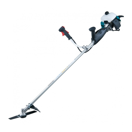
ONCEPT AND MAIN APPLICATIONS
Model RBC411U is Petrol brushcutter developed based on Model RBC411
powered by 40.2 cm³ 2-stroke engine; therefore, the engine for this model is not
complied with well-known exhaust emission regulations.
The development concept of this model is to increase maneuverability, while
providing a cost advantage with newly designed Shaft section.
Its other features are:
• Symmetric design handle bar
• Ergonomic grip for higher maneuverability
S
pecification
Type
Displacement: cm³
Fuel
Engine
Max. output: kW (PS)
Max. torque: N.m
Max. speed at no load: min.
Max. spindle speed at no load: min.
Compliance with main exhaust
emission regulations; CARB Tier 3,
EPA Phase 2, EU Stage 2
Carburetor
Rapid start
Starting
(Spring-assisted recoil starter)
system
Decompression valve
Starting system
Fuel tank capacity: L
Primer pump
Spindle thread size
Handle style
Net weight*: kg (lbs)
* Dry weight, without guard, cutting tool and shoulder harness
S
tandard equipment
Double blade 305mm (12") ................................................................ 1
Tool kit
(inc. Socket wrench 17-19, Hex wrench 4 and Hex wrench 5) .......... 1
Shoulder harness with double shoulder straps .................................... 1
Accessory bag ..................................................................................... 1
Note: The standard equipment for the tool shown above may vary by country.
O
ptional accessories
Triple blade 255mm (10"), Triple blade 305mm (12"), Star blade 230mm (9"), Star blade 255mm (10"),
Double blade 305mm (12"), Eddy blade (8-tooth blade) 230mm (9"), Eddy blade (8-tooth blade) 255mm (10"),
Saw blade 230mm (9"), Saw blade 255mm (10"), Nylon cutting head (Bump & Feed Z5L),
Nylon cutting head (Ultra Auto 6L), Protector (for cutting blade only), Universal guard (=Protector),
Universal guard extension
RBC411U
Petrol Brushcutter
¹ = rpm
ˉ
¹ = rpm
ˉ
2-stroke
40.2
Mixed gasoline
1.4 (2.0) [at 7,000 min.
2.2 [at 5,000 min.
¹]
ˉ
10,000
6,800
No
Float type
No
No
Recoil starter
1.1
No
M10x1.25, Left-handed
Symmetric design bike handle
7.3 (16)
PRODUCT
P 1/ 15
H
W
L
Dimensions: mm (")
Length (L)
1,710 (67-1/2)
Width (W)
670 (26-3/8)
Height (H)
430 (17)
¹]
ˉ
Advertisement

Related Manuals for Makita RBC411U


Summary of Contents for Makita RBC411U
- Page 1 Description Petrol Brushcutter ONCEPT AND MAIN APPLICATIONS Model RBC411U is Petrol brushcutter developed based on Model RBC411 powered by 40.2 cm³ 2-stroke engine; therefore, the engine for this model is not complied with well-known exhaust emission regulations. The development concept of this model is to increase maneuverability, while providing a cost advantage with newly designed Shaft section.
-
Page 2: Necessary Repairing Tools
(1) Apply 1g of Makita grease N No. 2 to Spiral spring in Recoil starter. (2) When the inside of Gear case assembly is cleaned, supply 11g of Makita grease N No. 2 from the grease inlet. (3) Apply 6g of Makita grease N No. 1 to the entire portion of Shaft complete in Shaft pipe complete. - Page 3 P 3/ 15 epair [4] DISASSEMBLY/ ASSEMBLY [4]-2. Engine and Shaft DISASSEMBLING (1) Remove M6x22 Hex socket head bolt that fastens Earth terminal to Clutch case complete. Disconnect Bullet terminals of Lead wires. (Fig. 1) (2) Loosen Mixing cap of Carburetor, then remove Piston valve from Carburetor. Push Piston valve against the spring force to separate the cable end from Piston valve.
- Page 4 Gear case assembly • Ball bearing 6000ZZ must be close to Retaining ring S-10. (See Fig. 8) • When the gear room is cleaned up, apply 11g Makita grease N No.2 into Gear case assembly from the grease U-shape table inlet.
- Page 5 P 5/ 15 epair [4] DISASSEMBLY/ ASSEMBLY [4]-5. Control lever assembly ASSEMBLING See Fig. 12. (1) Hook Control cable to Throttle lever. Fig. 12 Assemble Switch lever and Leaf spring to Switch cover. Torsion spring 11 Lever (2) Assemble Throttle lever, Lock off lever and Switch cover to case L Switch cover Lever case L in order while setting the following parts in place:...
- Page 6 P 6/ 15 epair [4] DISASSEMBLY/ ASSEMBLY [4]-7. Clutch drum complete DISASSEMBLING (1) Remove M6x14 Hex head bolt and Flat washer 6 from Clutch drum complete while inserting Hex wrench into Gear case assembly and pretighten Receive washer and Clamp washer with M10 Nut to prevent the rotation of Shaft complete.
- Page 7 P 7/ 15 epair [4] DISASSEMBLY/ ASSEMBLY [4]-7. Clutch drum complete (cont.) ASSEMBLING (1) After putting Retaining ring R-35 on the center of Clutch drum complete, pressfit Ball bearing 6003LLU in place of Clutch drum complete with 1R028. (Fig. 23) Fit Retaining ring S-17 into the groove of Clutch drum complete with 1R004.
- Page 8 P 8/ 15 epair [4] DISASSEMBLY/ ASSEMBLY [4]-8. Ignition CHECK OF PLUG CAP (SPRING) (1) Remove Plug cap from Spark plug, then detect the continuity between Plug cap spring in Plug cap and Earth terminal of Ignition coil. It is the normal condition when Tester shows 2.45kΩ±10%. (Fig. 26) (2) In case of no continuity or unstable continuity, check the connection between Plug cap spring and Ignition coil as follows: (A) Spray the lubricant in Plug cap, then pull out Plug cap spring together with Ignition cable using Pliers.
- Page 9 P 9/ 15 epair [4] DISASSEMBLY/ ASSEMBLY [4]-8. Ignition (cont.) REMOVING OF IGNITION COIL (1) Remove M5x50 Hex socket head bolt and two M5x22 Hex socket head bolts (with washers and super lock washers) and four M5x14 Pan head screws (with washers and spring lock washers), and then separate Blower housing, Muffler cover and Cylinder cover from the machine.
- Page 10 P 10/ 15 epair [4] DISASSEMBLY/ ASSEMBLY [4]-9. Flywheel Note: • Flywheel can be easily removed with Impact driver without holding the piston. • Do not remove Spark plug as compressed air resistance in Cylinder has to be used for the disassembling. •...
- Page 11 - Rewind the spring counterclockwise toward the center of circle. (Fig. 38) Hook in Reel (2) Apply a little amount of Makita grease N No.2 to the spring. for Spiral spring (3) Make a knot on the new rope end and pass it through Reel and Base of Starter case assembly, then connect the other end to Starter knob.
- Page 12 P 12/ 15 epair [4] DISASSEMBLY/ ASSEMBLY [4]-11. Air cleaner assembly, Carburetor DISASSEMBLING Fig. 42 (1) Remove Air cleaner cover by unscrewing M5x20 Pan head screw. (Fig. 42) (2) Remove Element, then separate Air cleaner plate from Carburetor by unscrewing two M5x14 Pan head screws.
- Page 13 P 13/ 15 epair [4] DISASSEMBLY/ ASSEMBLY [4]-11. Air cleaner assembly, Carburetor (cont.) REPLACING/ MAINTENANCE OF CARBURETOR See Fig. 46 for the all components of Carburetor. (1) Push Jet needle against Spring while holding Piston valve. Spring plate is unlocked and removed. Check whether the engagement of E-ring to the groove of Jet needle is loose or not.
- Page 14 P 14/ 15 epair [4] DISASSEMBLY/ ASSEMBLY [4]-12. Engine block Fig. 52 DISASSEMBLING (1) It is highly recommended to drain the oil system of Engine block before starting disassembling because the oil remaining there will drip out to delay your operation. (2) From the engine section, remove the following parts: Cylinder cover, Fuel tank, Blower housing, Muffler cover, Recoil starter Cylinder...
- Page 15 P 15/ 15 epair [4] DISASSEMBLY/ ASSEMBLY [4]-13. Stop switch Fig. 57 CHECKING STOP SWITCH Check the continuity between the bullet terminals on the two lead wires extending from Control lever with a circuit tester. (Fig. 57) If Stop switch functions properly, there will be no continuity with the switch ON and there will be continuity with the switch OFF.