Honeywell T8601D Installation Manual
Chronotherm iv
deluxe zone thermostats
Hide thumbs
Also See for T8601D:
- Product data (28 pages) ,
- Owner's manual (21 pages) ,
- Installation instructions manual (12 pages)
Advertisement
Table of Contents
APPLICATION
The T8601D Chronotherm
stage zoned heating and cooling system. Refer to Table 1 for a general description of the thermostats.
Model
T8601D2027 Zone 1 on MiniZone™
panel and MABS II or any
zone on TZ-3, EMM-3,
EMM-3U, EZ-2, or EZ-4
systems.
a
Use manual changeover on MiniZone zone 1.
MERCURY NOTICE
If this control is replacing a control that contains
mercury in a sealed tube, do not place your old
control in the trash. Dispose of properly.
Contact your local waste management authority
for instructions regarding recycling and the
proper disposal of the old control.
INSTALLATION
When Installing this Product...
1. Read these instructions carefully. Failure to follow
the instructions can damage the product or cause
a hazardous condition.
2. Check the ratings given in the instructions and on
the product to make sure the product is suitable for
your application.
3. Installer must be a trained, experienced service
technician.
4. After completing installation, use these instructions
to check out the product operation.
Location
Install the thermostat about 1.5m (5 ft) above the floor in
an area with good air circulation at average temperature.
See Fig. 1.
® U.S. Registered Trademark
Copyright © 2002 Honeywell •
T8601D Chronotherm
Deluxe Zone Thermostats
®
IV Deluxe Zone Thermostats provide programmable electronic control of 24 Vac single-
Table 1. Description of T8601D Thermostat.
Application
Powering Method
Requires common
wire to power supply.
• All Rights Reserved
INSTALLATION INSTRUCTIONS
Changeover System Selection Fan Selection
Automatic or
Heat-Off-Cool-Auto
a
manual
Do not install the thermostat where it can be affected by:
— drafts, or dead spots behind doors and in corners.
— hot or cold air from ducts.
— radiant heat from sun or appliances.
— concealed pipes and chimneys.
— unheated (uncooled) areas such as an outside wall
behind the thermostat.
Wallplate Installation
The thermostat can be mounted horizontally on the wall
or on a 2 in. x 4 in. (50.8 mm x 101.6 mm) wiring box.
Position wallplate horizontally on the wall or on a
2 in. x 4 in. (50.8 mm x 101.6 mm) wiring box.
1. Position and level the wallplate (for appearance
only). The thermostat will function correctly even
when not level.
2. Use a pencil to mark the mounting holes.
See Fig. 2.
3. Remove the wallplate from the wall and drill two
3/16 inch (76 mm) holes in the wall (if drywall) as
marked. For firmer material such as plaster, drill
two 7/32 inch (5.56 mm) holes. Gently tap anchors
(provided) into the drilled holes until flush with the
wall.
4. Position the wallplate over the holes, pulling wires
through the wiring opening.
5. Loosely insert the mounting screws into the holes.
6. Tighten mounting screws.
®
IV
On-Auto
69-1413-2
Advertisement
Table of Contents

Related Manuals for Honeywell T8601D


Summary of Contents for Honeywell T8601D
- Page 1 The T8601D Chronotherm IV Deluxe Zone Thermostats provide programmable electronic control of 24 Vac single- stage zoned heating and cooling system. Refer to Table 1 for a general description of the thermostats. Table 1. Description of T8601D Thermostat. Model Application...
- Page 2 1. Loosen the terminal screws on the wallplate and CHANGEOVER CONTROL M12182 connect the system wires. See Fig. 5. Fig. 3. Typical wiring diagram for T8601D on zone 1 IMPORTANT of MiniZone™ or MABS II control panels. Use 18 gauge, color-coded thermostat cable for proper wiring.
-
Page 3: Mounting Thermostat
TO OC ON TZ-3 TotalZone® PANEL THERMOSTAT CONNECTIONS O,B AND STAGE JUMPER MUST BE CONFIGURED FOR TZ-3. M12183A ENGAGE TABS Fig. 4. Typical wiring diagram for T8601D TotalZone®, AT TOP OF THERMOSTAT EMM-3, EMM-3U, EZ-2, EZ-4 control panels. AND WALLPLATE. -
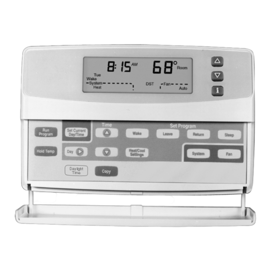
Page 4: Temperature Settings
DAY TO ANOTHER DAY SETPOINTS INSTALLER SETUP AND SYSTEM TEST M14624 Fig. 7. T8601D key locations and descriptions. SETTINGS Temperature Settings Refer to Table 2 for the default program. If the daytime energy savings period is not used, press the period key System and Fan Settings (Leave or Return) until the time is blank. - Page 5 ® T8601D CHRONOTHERM IV DELUXE ZONE THERMOSTATS The Installer Setup is used to customize the thermostat to specific systems. Some of the options include temperature display, changeover, and outdoor temperature display. Installer Setup numbers are listed in Table 3. The table includes all the configuration options and the factory settings for the T8601.
- Page 6 ® T8601D CHRONOTHERM IV DELUXE ZONE THERMOSTATS Table 4. Thermostat Installer Setup Options. (Continued) Installer Setup Other Choices Number (Press Factory Setting (Press s or t key to change) Time ∆ key to Actual Select change) Display Description Display Description Setting Not Used.
- Page 7 ® T8601D CHRONOTHERM IV DELUXE ZONE THERMOSTATS Table 4. Thermostat Installer Setup Options. (Continued) Installer Setup Other Choices Number (Press Factory Setting (Press s or t key to change) Time ∆ key to Actual Select change) Display Description Display Description...
-
Page 8: Setting Current Day And Time
® T8601D CHRONOTHERM IV DELUXE ZONE THERMOSTATS Setting Current Day and Time 1. Reset the timer by pressing the i key until the expired timer is displayed. 1. Press Set Current Day/Time. NOTE: On initial powerup or after an extended power loss, 1:00 pm flashes on the display until a key is pressed. - Page 9 ® T8601D CHRONOTHERM IV DELUXE ZONE THERMOSTATS System Wait Set Program Set Day/Time Temporary Setting Em Heat Recovery Cool Hold for Auto Em Ht Aux Ht Filter Days Repl Batt Room Outdoor Tue Wed Thu Fri Sat Sun Heat Cool...
-
Page 10: Thermostat Information
® T8601D CHRONOTHERM IV DELUXE ZONE THERMOSTATS THERMOSTAT INFORMATION 4. Press the increase s key again to display the soft- ware revision number. (Example: 001 = Revision number 1). 1. Press the Time ∆ key to access the thermostat information. -
Page 11: Troubleshooting Guide
® T8601D CHRONOTHERM IV DELUXE ZONE THERMOSTATS TROUBLESHOOTING GUIDE Table 7. Troubleshooting Guide. Symptom Possible Cause Action Display does not Thermostat is not being • Check for 24 Vac between R and C terminals. come on. powered. — If missing 24 Vac: —... - Page 12 ® T8601D CHRONOTHERM IV DELUXE ZONE THERMOSTATS Automation and Control Solutions Honeywell Honeywell Limited-Honeywell Limitée 1985 Douglas Drive North 35 Dynamic Drive Golden Valley, MN 55422 Scarborough, Ontario M1V 4Z9 69-1413—2 G.H. Rev. 12-02 www.honeywell.com/yourhome...