Hitachi wj200 series Quick Reference Manual
Hide thumbs
Also See for wj200 series:
- Instruction manual (421 pages) ,
- Quick reference manual (131 pages) ,
- Installation manual (20 pages)
Table of Contents
Advertisement
Advertisement
Table of Contents

Related Manuals for Hitachi wj200 series


Summary of Contents for Hitachi wj200 series
- Page 1 WJ200 Series Inverter Quick Reference Guide • Single-phase Input 200V class • Three-phase Input 200V class • Three-phase Input 400V class Manual Number: NT3381AX Refer to the user manual for detail April 2016 Hitachi Industrial Equipment Systems Co., Ltd.
-
Page 3: Safety Precautions
Introduction Thank you for purchasing the Hitachi WJ200 series inverter. Please read this Quick Reference Guide (QRG) and Instruction manual, and understand perfectly how to handle properly and the safety cautions of the product before operation, for safety and proper usage. - Page 4 2. Wiring WARNING - Be sure to ground the inverter. Otherwise, you run the risk of electric shock or fire. - Commit wiring work to a qualified electrician. Otherwise, you run the risk of electric shock or fire. - Before wiring, make sure that the power supply is off. Otherwise, you run the risk of electric shock or fire.
- Page 5 CAUTION - Do not touch the heat sink, which heats up during the inverter operation. Otherwise, you run the risk of burn injury. - The inverter allows you to easily control the speed of motor or machine operations. Before operating the inverter, confirm the capacity and ratings of the motor or machine controlled by the inverter.
- Page 6 UL® ® ® ® Cautions, Warnings and Instructions Warnings and Cautions for Troubleshooting and Maintenance (Standard to comply with : UL508C,CSA C22.2 No.14-05) Warning Markings GENERAL: These devices are open type Power Conversion Equipment. They are intended to be used in an enclosure.
- Page 7 Terminal symbols and Screw size Required Inverter Model Screw Size Wire range Torque (N-m) WJ200-001S WJ200-002S M3.5 AWG16 (1.3mm WJ200-004S WJ200-007S AWG12 (3.3mm WJ200-015S AWG10 (5.3mm WJ200-022S WJ200-001L WJ200-002L M3.5 AWG16 (1.3mm WJ200-004L WJ200-007L WJ200-015L AWG14 (2.1mm WJ200-022L AWG12 (3.3mm WJ200-037L AWG10 (5.3mm WJ200-055L...
-
Page 8: Fuse Sizes
Fuse Sizes Distribution fuse size marking is included in the manual to indicate that the unit shall be connected with a Listed Cartridge Nonrenewable fuse, rated 600 Vac with the current ratings as shown in the table below or Type E Combination Motor Controller marking is included in the manual to indicate that the unit shall be connected with, LS Industrial System Co.,Ltd,Type E Combination Motor Controller MMS Series with the ratings as shown in the table below: Inverter Model... -
Page 9: Inverter Specification Label
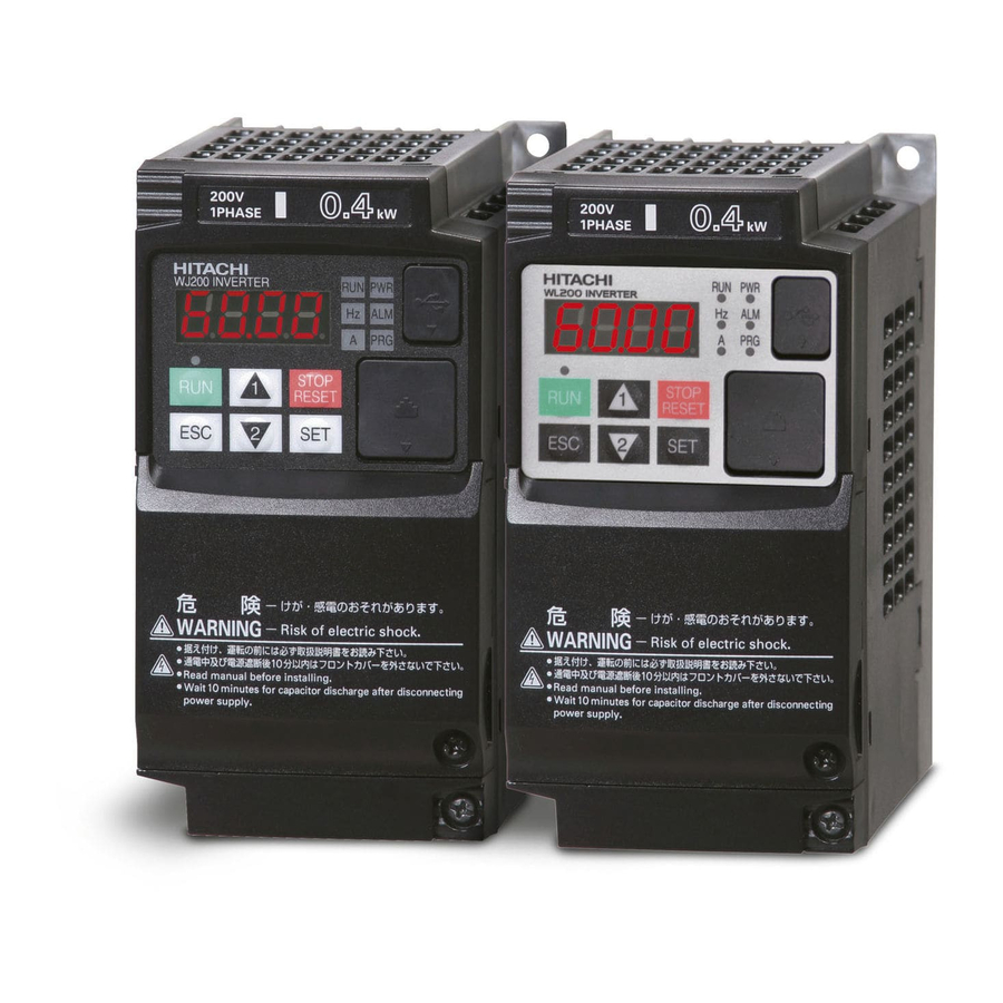
Inverter Specification Label The Hitachi WJ200 inverters have product labels located on the right side of the housing, as pictured below. Be sure to verify that the specifications on the labels match your power source, and application safety requirements. Model name Version Ver.3.0 followed... -
Page 10: Wj200 Inverter Specifications
WJ200 Inverter Specifications Model-specific tables for 200V and 400V class inverters The following tables are specific to WJ200 inverters for the 200V and 400V class model groups. Item Single-phase 200V class Specifications WJ200 inverters, 200V models 001SF 002SF 004SF 007SF 015SF 022SF Applicable motor size... - Page 11 WJ200 Inverter Specifications, continued… Item Three-phase 200V class Specifications WJ200 inverters, 200V models 001LF 002LF 004LF 007LF 015LF 022LF Applicable motor size 0.75 0.75 Rated capacity (kVA) 200V 240V Rated input voltage Three-phase: 200V-15% to 240V +10%, 50/60Hz ±5% Rated output voltage Three-phase: 200 to 240V (proportional to input voltage) Rated output current (A) 12.0...
- Page 12 WJ200 Inverter Specifications, continued… Item Three-phase 400V class Specifications WJ200 inverters, 400V models 004HF 007HF 015HF 022HF 030HF 040HF Applicable motor size 0.75 0.75 Rated capacity (kVA) 380V 480V Rated input voltage Three-phase: 400V-15% to 480V +10%, 50/60Hz ±5% Rated output voltage Three-phase: 400 to 480V (proportional to input voltage) Rated output current (A) 11.1...
- Page 13 The following table shows which models need derating. 1-ph 200V class Need 3-ph 200V class Need 3-ph 400V class Need derating derating derating WJ200-001S WJ200-001L WJ200-004H - - WJ200-002S WJ200-002L WJ200-007H - WJ200-004S WJ200-004L WJ200-015H - WJ200-007S WJ200-007L WJ200-022H - -...
-
Page 14: Basic System Description
Basic System Description A motor control system will obviously include a motor and inverter, as well as a circuit breaker or fuses for safety. If you are connecting a motor to the inverter on a test bench just to get started, that’s all you may need for now. But a system can also have a variety of additional components. - Page 15 Determining Wire and Fuse Sizes The maximum motor current in your application determines the recommended wire size. The following table gives the wire size in AWG. The “Power Lines” column applies to the inverter input power, output wires to the motor, the earth ground connection, and any other components shown in the “Basic System Description”...
- Page 16 Wire the Inverter Input to a Supply In this step, you will connect wiring to the input of the inverter. First, you must determine whether the inverter model you have required three-phase power only, or single-phase power only. All models have the same power connection terminals [R/L1], [S/L2], and [T/L3].
- Page 17 Three-phase 200V 3.7kW Three-phase 400V 4.0kW PD/+1 R/L1 S/L2 T/L3 U/T1 V/T2 W/T3 Chassis Ground (M4) Power input Output to Motor Three-phase 200V 5.5, 7.5kW Three-phase 400V 5.5, 7.5kW R/L1 S/L2 T/L3 U/T1 V/T2 W/T3 PD/+1 Power input Output to Motor...
- Page 18 Three-phase 200V 11kW Three-phase 400V 11, 15kW R/L1 S/L2 T/L3 U/T1 V/T2 W/T3 PD/+1 Power input Output to Motor Three-phase 200V 15kW R/L1 S/L2 T/L3 U/T1 V/T2 W/T3 PD/+1 Power input Output to Motor NOTE: An inverter powered by a portable power generator may receive a distorted power waveform, overheating the generator.
-
Page 19: Using The Front Panel Keypad
Using the Front Panel Keypad Please take a moment to familiarize yourself with the keypad layout shown in the figure below. The display is used in programming the inverter’s parameters, as well as monitoring specific parameter values during operation. (1) POWER LED (4) RUN LED (5) Monitor LED [Hz] (2) ALARM LED... - Page 20 You can see from the following page how to monitor and/or program the parameters. Keypad Navigation Map The WJ200 Series inverter drives have many programmable functions and parameters. The following pages will cover these in detail, but you need to access just a few items to perform the powerup test.
- Page 21 Func. code display : Moves to data display Group "d" Func. code display d001 0.00 d002 Func. code display : Jumps to the next group d104 Group "F" Func. code display Save F001 50.00 F002 50.01 F004 Data display (F001 to F003) Data does not blink because of real time synchronizing : Saves the data in EEPROM and returns to...
- Page 22 [Setting example] After power ON, changing from 0.00 display to change the A002 (Run command source) data. d001 Data of will be shown on the Press [ESC] key to show display after the first power ON the function code 0.00 d001 Press [ESC] key to move F001...
- Page 23 When a function code is shown… When a data is shown… Cancels the change and moves back to the ESC key Move on to the next function group function code Fix and stores the data and moves back to SET key Move on to the data display the function code Increase function code...
-
Page 24: Connecting To Plcs And Other Devices
Connecting to PLCs and Other Devices Hitachi inverters (drives) are useful in many types of applications. During installation, the inverter keypad (or other programming device) will facilitate the initial configuration. After installation, the inverter will generally receive its control commands through the control logic connector or serial interface from another controlling device. - Page 25 Example Wiring Diagram The schematic diagram below provides a general example of logic connector wiring, in addition to basic power and motor wiring converted in the preceding pages. The goal of this page is to help you determine the proper connections for the various terminals shown below for your application needs.
-
Page 26: Control Logic Signal Specifications
Control Logic Signal Specifications The control logic connectors are located just behind the front housing cover. The relay contacts are just to the left of the logic connectors. Connector labeling is shown below. RS485 comm. Logic inputs Relay contacts Jumper wire SP EO AM CM2 Pulse... - Page 27 Terminal Name Description Ratings Analog voltage input 0 to 9.8 VDC range, 10 VDC nominal, input impedance 10 kΩ +10V analog reference 10VDC nominal, 10mA max. SP, SN Serial communication terminal For RS485 Modbus communication. AL0, AL1, AL2 *3 Relay common contact 250VAC, 2.5A (R load) max.
- Page 28 Source or sink logic is switched by a jumper wire as below. Source logic Sink logic PLC P24 PLC P24 Jumper wire Jumper wire Wire size for control and relay terminals Use wires within the specifications listed below. For safe wiring and reliability, it is recommended to use ferrules, but if solid or stranded wire is used, stripping length should be 8mm.
- Page 29 Recommended ferrule For safe wiring and reliability, it is recommended to use following ferrules. Φ Φd [mm] ΦD [mm] Wire size Model name of L [mm] (AWG) ferrule * 0.25 (24) AI 0.25-8YE 12.5 0.34 (22) AI 0.34-8TQ 12.5 0.5 (20) AI 0.5-8WH Φ...
-
Page 30: Intelligent Terminal Listing
Intelligent Terminal Listing Intelligent Inputs The following table shows the list of the functions which can be assigned to each intelligent input. Please refer to the Instruction manual for the detail information. Input Function Summary Table Symbol Code Function Name Forward Run/Stop Reverse Run/Stop Multi-speed Select, Bit 0 (LSB) - Page 31 Input Function Summary Table Symbol Code Function Name Rotation direction detection (phase B) DISP Display limitation PSET "PSET" simple position control retains preset place. No assign Intelligent Outputs The following table shows the list of the functions which can be assigned to each intelligent input.
-
Page 32: Using Intelligent Input Terminals
Using Intelligent Input Terminals Terminals [1], [2], [3], [4], [5], [6] and [7] are identical, programmable inputs for general use. The input circuits can use the inverter’s internal (isolated) +24V field supply or an external power supply. This section describes input circuits operation and how to connect them properly to switches or transistor outputs on field devices. - Page 33 The two diagrams below input wiring circuits using the inverter’s internal +24V supply. Each diagram shows the connection for simple switches, or for a field device with transistor outputs. Note that in the lower diagram, it is necessary to connect terminal [L] only when using the field device with transistors.
- Page 34 The two diagrams below show input wiring circuits using an external supply. If using the “Sinking Inputs, External Supply” in below wiring diagram, be sure to remove the jumper wire, and use a diode (*) with the external supply. This will prevent a power supply contention in case the jumper wire is accidentally placed in the incorrect position.
- Page 35 CAUTION: Be sure to connect diode in between "P24" and "PLC" when connecting plural inverters with digital input wiring in common. By having ability inverter doesn’t block the current flowing into itself when it is not powered. This may cause the closed circuit when two or more inverters are connected to common I/O wiring as shown below to result in unexpected turning the on the input.
- Page 36 Forward Run/Stop and Reverse Run/Stop Commands: When you input the Run command via the terminal [FW], the inverter executes the Forward Run command (high) or Stop command (low). When you input the Run command via the terminal [RV], the inverter executes the Reverse Run command (high) or Stop command (low).
- Page 37 Multi-Speed Select ~Binary Operation The inverter can store up to 16 different target Multi- Input Function speed frequencies (speeds) that the motor output uses for CF4 CF3 CF2 CF1 steady-state run condition. These speeds are accessible Speed 0 through programming four of the intelligent terminals as Speed 1 binary-encoded inputs CF1 to CF4 per the table to the Speed 2...
- Page 38 Two Stage Acceleration and Deceleration When terminal [2CH] is turned ON, the inverter Target changes rate acceleration frequency deceleration from the initial settings (F002 F003) to use the second set of acceleration/ second Output deceleration values. When the terminal is initial frequency turned OFF, the inverter is returned to the...
-
Page 39: Unattended Start Protection
Unattended Start Protection If the Run command is already set when power is turned ON, the inverter starts running immediately after powerup. The Unattended Start Protection (USP) function prevents that automatic startup, so that the inverter will not run without outside intervention. When USP is active and you need to reset an alarm and resume running, either turn the Run command OFF, or perform a reset operation by the terminal [RS] input or the keypad Stop/reset key. -
Page 40: Reset Inverter
Reset Inverter The [RS] terminal causes the inverter to execute 12 ms the reset operation. If the inverter is in Trip Mode, minimum [RS] the reset cancels the Trip state. When the signal [RS] is turned ON and OFF, the inverter executes Approx. -
Page 41: Using Intelligent Output Terminals
Using Intelligent Output Terminals Run Signal When the [RUN] signal is selected as an [FW,RV] intelligent output terminal, the inverter outputs a signal on that terminal when it is in Run B082 Mode. The output logic is active low, and is Output the open collector type (switch to ground). - Page 42 Frequency Arrival Signals The Frequency Arrival group of outputs helps coordinate external systems with the current velocity profile of the inverter. As the name implies, output [FA1] turns ON when the output frequency arrives at the standard set frequency (parameter F001). Output [FA2] relies on programmable accel/ decel thresholds for increased flexibility.
- Page 43 Frequency arrival output [FA1] uses the standard output frequency (parameter F001) as the threshold for switching. In the figure to the right, Frequency Arrival [FA1] turns when output F001 Foff Output frequency gets within Fon Hz below or F001 freq. Fon Hz above the target constant frequency, where Fon is 1% of the set Foff...
- Page 44 sets of parameters.
-
Page 45: Alarm Signal
Alarm Signal The inverter alarm signal is active when a fault has STOP RESET occurred and it is in the Trip Mode (refer to the Stop diagram at right). When the fault is cleared the alarm signal becomes inactive. STOP RESET We must make a distinction between the alarm signal AL and the alarm relay contacts [AL0], [AL1] and [AL2]. - Page 46 The alarm relay output can be configured in two main ways: Trip/Power Loss Alarm – The alarm relay is configured as normally closed (C036=01) • by default, shown below (left). An external alarm circuit that detects broken wiring also as an alarm connects to [AL0] and [AL1]. After powerup and short delay (< 2 seconds), the relay energizes and the alarm circuit is OFF.
-
Page 47: Analog Input Operation
Analog Input Operation AM H O OI L The WJ200 inverters provide for analog input to +V Ref. command the inverter frequency output value. The analog input terminal group includes the [L], Voltage input [OI], [O], and [H] terminals on the control Current input connector, which provide for Voltage [O] or Current [OI] input. - Page 48 A005 The following table shows the available analog input settings. Parameter and the input terminal [AT] determine the External Frequency Command input terminals that are available, and how they function. The analog inputs [O] and [OI] use terminal [L] as the reference (signal return).
-
Page 49: Pulse Train Input Operation
Pulse Train Input Operation The WJ200 inverter is capable of accepting pulse train input signals, which are used for frequency command, process variable (feedback) for PID control, and simple positioning. The dedicated terminal is called “EA” and “EB”. Terminal “EA” is a dedicated terminal, and the terminal “EB”... -
Page 50: Analog Output Operation
Analog Output Operation AM H O OI L In inverter applications it is useful to monitor the inverter operation from a remote location or from the Analog front panel of an inverter enclosure. In some cases, A GND Voltage this requires only a panel-mounted volt meter. In other Output cases, a controller such as a PLC may provide the 10VDC... - Page 51 The [AM] signal offset and gain are adjustable, as indicated below. Func. Description Range Default C106 [AM] output gain 0.~255. 100. C109 [AM] output offset 0.0~10.0 The graph below shows the effect of the gain and offset setting. To calibrate the [AM] output for your application (analog meter), follow the steps below: 1.
- Page 52 Monitoring functions NOTE: Parameters marked with " " in A column are accessible even in inverter running. Parameters marked with " " in B column are accessible even in inverter running when in the high level access mode, which means that b031 is set to "10". B037 * Please change from"...
- Page 53 “d” Function Units Func. Name Description Code D006 Intelligent output Displays the state of the intelligent terminal status output terminals: − − − Relay 12 11 D007 Scaled output frequency Displays the output frequency scaled by the constant in B086. monitor Hz times constant...
- Page 54 “d” Function Units Func. Name Description Code d029 Positioning command monitor Displays the positioning command, − − − range is –268435455 to +268435455 d030 Current position monitor Displays the current position, range − − − is –268435455 to +268435455 d050 Dual monitor Displays two different data configured in b160 and b161.
- Page 55 Main Profile Parameters NOTE:. Parameters marked with " " in A column are accessible even in inverter running. Parameters marked with " " in B column are accessible even in inverter running when in the high level access mode, which means that b031 is set to "10". “F”...
- Page 56 Standard Functions NOTE:. Parameters marked with " " in A column are accessible even in inverter running. Parameters marked with " " in B column are accessible even in inverter running when in the high level access mode, which means that b031 is set to "10". “A”...
- Page 57 “A” Function Defaults Func. Name Description Initial data Units Code A012 [O] input active range The output frequency end frequency corresponding to the analog input range ending point, 0.00 range is 0.00 to 400.0(580.0) A013 [O] input active range The starting point (offset) for start voltage the active analog input range, range is 0.
- Page 58 “A” Function Defaults Func. Name Description Initial data Units Code A039 Jog stop mode Define how end of jog stops the motor; six options: 00…Free-run stop (invalid during run) 01…Controlled deceleration (invalid during run) 02…DC braking to stop − (invalid during run) 03…Free-run stop (valid during run) 04…Controlled deceleration...
- Page 59 “A” Function Defaults Func. Name Description Initial data Units Code A051 DC braking enable Three options; select codes: 00…Disable 01…Enable during stop − 02…Frequency detection A052 DC braking frequency The frequency at which DC braking begins, range is from the start frequency (B082) to 60Hz A053 DC braking wait time...
- Page 60 “A” Function Defaults Func. Name Description Initial data Units Code A062 Frequency lower limit Sets a limit on output frequency greater than zero. Range is start frequency (B082) to frequency upper 0.00 limit (A061) 0.0 setting is disabled >0.0 setting is enabled A262 Frequency lower limit, Sets a limit on output...
- Page 61 “A” Function Defaults Func. Name Description Initial data Units Code A077 Reverse PID action Two option codes: 00…PID input = SP-PV − 01…PID input = -(SP-PV) A078 PID output limit Sets the limit of PID output as percent of full scale, range is 0.0 to 100.0% a079 PID feed forward...
- Page 62 “A” Function Defaults Func. Name Description Initial data Units Code A095 Acc1 to Acc2 frequency Output frequency at which transition point Accel1 switches to Accel2, 0.00 range is 0.00 to A295 Acc1 to Acc2 frequency 400.0(580.0) transition point, 2 0.00 motor A096 Dec1 to Dec2 frequency...
- Page 63 “A” Function Defaults Func. Name Description Initial data Units Code A141 A input select for Seven options: 00…Operator calculate function 01…POT on ext. Operator *Valid when connecting OPE-SR/SRmini 02…Terminal [O] input − 03…Terminal [OI] input 04…RS485 05…Option 07…Pulse train input A142 B input select for Seven options:...
- Page 64 “A” Function Defaults Func. Name Description Initial data Units Code a155 Deceleration hold time Sets the duration of deceleration hold, range is 0.0 to 60.0 seconds a156 PID sleep function Sets the threshold for the action threshold action, set range 0.00 to 0.00 400.0(580.0) a157...
- Page 65 Fine Tuning Functions “b” Function Defaults Func. Name Description Initial data Units Code B001 Restart mode on Select inverter restart method, power failure / Five option codes: 00…Alarm output after trip, no automatic under-voltage trip restart 01…Restart at 0Hz 02…Resume operation after frequency −...
- Page 66 “b” Function Defaults Func. Name Description Initial data Units Code b011 Retry wait time on Range is 0.3 to 100 sec. over voltage / over current trip B012 Level of electronic Set a level between 20% and 100% of the Rated thermal rated inverter current.
- Page 67 “b” Function Defaults Func. Name Description Initial data Units Code b024 Overload Select the operation mode during overload restriction conditions, four options, option codes: 00…Disabled operation mode 2 01…Enabled for acceleration and constant − speed 02…Enabled for constant speed only 03…Enabled for acceleration and constant speed, increase speed at regen.
- Page 68 “b” Function Defaults Func. Name Description Initial data Units Code b037 Function code Six option codes: 00…Full display display restriction 01…Function-specific display 02…User setting (and b037) − 03…Data comparison display 04…Basic display 05…Monitor display only b038 000…Initial display selection by SET key. Initial display 001 to030…d001 to d030 displayed selection...
- Page 69 “b” Function Defaults Func. Name Description Initial data Units Code B061 Minimum-limit Set range, 0 to {Max.-limit level (b060) - level of window hysteresis width (b062)x2} % (Maximum of 0%) comparator (O) B062 Hysteresis width Set range, 0 to {Max.-limit level (b060) - of window Min.-limit level (b061)}/2 % (Maximum of 10%) comparator (O)
- Page 70 “b” Function Defaults Func. Name Description Initial data Units Code b089 Automatic carrier Three option codes: 00…Disabled frequency 01…Enabled, depending on the output current reduction − 02…Enabled, depending on the heat-sink temperature b090 Dynamic braking Selects the rate of use (in %) of the usage ratio regenerative braking resistor per 100 sec.
- Page 71 “b” Function Defaults Func. Name Description Initial data Units Code b105 Free V/F setting, Set range, 0 to 800V voltage.3 b106 Set range, value of b104 to b108 Free V/F setting, freq.4 b107 Free V/F setting, Set range, 0 to 800V voltage.4 b108 Set range, value of b108 to b110...
- Page 72 “b” Function Defaults Func. Name Description Initial data Units Code B134 Decel. overvolt. Integration time when b130=01. Range is: 0.0 suppress integral to 150.0 time b145 GS input mode Two option codes: 00…No trip (Hardware shutoff only) 01…Trip (E37) …Trip (E98/E99) or hardware shutoff (-S--) …Trip (E99) or hardware shutoff (-S--) −...
- Page 73 “b” Function Defaults Func. Name Description Initial data Units Code b190 Password 0000(Invalid Password) 0000 − Settings A 0001-FFFF(Password) b191 Password 0000-FFFF 0000 − authentication A b192 Password 0000(Invalid Password) 0000 − Settings B 0001-FFFF(Password) b193 Password 0000-FFFF 0000 − authentication B b910 00…OFF...
- Page 74 Intelligent Terminal Functions “C” Function Defaults Func. Initial Name Description Units Code data C001 Input [1] function Select input terminal [1] function, 68 − options (see next section) [FW] C002 Input [2] function Select input terminal [2] function, 68 − options (see next section) [RV] C003...
- Page 75 “C” Function Defaults Func. Initial Name Description Units Code data C028 [AM] terminal selection 11 programmable functions: 00…Output frequency (Analog voltage output 01…Output current 0...10V) 02…Output torque 04…Output voltage 05…Input power 06…Electronic thermal load ratio − [LAD] 07…LAD frequency 10…Heat sink temperature 11…Output torque (with code) 13…General output 16…Option...
- Page 76 “C” Function Defaults Func. Initial Name Description Units Code data C052 PID FBV output When the PV exceeds this value, the PID high limit loop turns OFF the PID second stage 100.0 output, range is 0.0 to 100% C053 PID FBV output When the PV goes below this value, the low limit PID loop turns ON the PID second stage...
- Page 77 “C” Function Defaults Func. Initial Name Description Units Code data C078 Communication wait time Time the inverter waits after receiving a message before it transmits. Range is 0. to 1000. ms C081 O input span calibration Scale factor between the external frequency command on terminals L–O 100.0 (voltage input) and the frequency output,...
- Page 78 “C” Function Defaults Func. Initial Name Description Units Code data C106 AM gain adjustment Set range is 50. to 200.% 100. C109 AM bias adjustment Set range is 0. to 100.% C111 Overload warning level 2 Sets the overload warning signal level Rated between 0% and 200% (from 0 to two time current...
- Page 79 “C” Function Defaults Func. Initial Name Description Units Code data C160 Input [1] response time Sets response time of each input terminal, − C161 Set range: 0 (x 2 [ms]) to 200 (x 2 [ms]) Input [2] response time − C162 Input [3] response time (0 to 400 [ms])
- Page 80 Input Function Summary Table – This table shows all thirty-one intelligent input functions at a glance. Detailed description of these functions, related parameters and settings, and example wiring diagrams are in “Using Intelligent Input Terminals” on page 30. Input Function Summary Table Option Terminal Function Name...
- Page 81 Input Function Summary Table Option Terminal Function Name Description Code Symbol Start Starts the motor rotation (3-wire interface) No change to present motor status Stops the motor rotation Stop (3-wire interface) No change to present motor status Selects the direction of motor rotation: ON = FWD. While the motor is rotating, a change of F/R will start a deceleration, followed by a change in FWD, REV...
- Page 82 Input Function Summary Table Option Terminal Function Name Description Code Symbol Setting of b040 is enabled Torque Limit Selection Max. torque is limited with 200% TRQ1 Torque limit switch 1 Torque limit related parameters of Powering/regen, and FW/RV modes are selected by the combinations of these inputs.
- Page 83 Input Function Summary Table Option Terminal Function Name Description Code Symbol Analog command is held Analog command hold Analog command is not held Multistage-position switch Multistage-position switch Multistage position commands are set according to the combination of these switches. Multistage-position switch Limit signal of homing is ON Limit signal of homing Limit signal of homing is OFF...
- Page 84 Output Function Summary Table – This table shows all functions for the logical outputs (terminals [11], [12] and [AL]) at a glance. Detailed descriptions of these functions, related parameters and settings, and example wiring diagrams are in “Using Intelligent Output Terminals”...
- Page 85 Output Function Summary Table Option Terminal Function Name Description Code Symbol Zero Hz Speed Output frequency falls below the threshold specified in C063 Detection Signal Output frequency is higher than the threshold specified in C063 Speed Deviation Deviation of speed command and actual speed exceeds the specified value P027.
- Page 86 Output Function Summary Table Option Terminal Function Name Description Code Symbol Cooling Fan Warning Lifetime of cooling fan has expired. Signal Lifetime of cooling fan has not expired. Starting Contact Signal Either FW or RV command is given to the inverter No FW or RV command is given to the inverter, or both are given to the inverter Heat Sink Overheat...
- Page 87 H001 Auto-tuning Three option codes: 00…Disabled selection 01…Enabled with motor stop − 02…Enabled with motor rotation H002 Motor constant Two option codes: 00…Hitachi standard motor selection − 02…Auto tuned data H202 Motor constant selection, 2 motor − H003 Motor capacity...
- Page 88 (Hitachi motor) H024 Motor constant J 0.001 to 9999 kgm (Hitachi motor) H224 Motor constant J, 2 motor (Hitachi motor) H030 Motor constant R1 0.001 to 65.535 ohms (Auto tuned data) H230 Motor constant R1, motor (Auto tuned data)
- Page 89 PM Motor Constants Functions “H” Function Defaults Func. Name Description Initial data Units Code 00…Hitachi standard (Use H106-H110 for motor constants) H102 01…Auto-Tuning PM motor code setting − (Use H109-H110, H111-H113 for motor constants) H103 0.1/0.2/0.4/0.55/0.75/1.1/1.5/2.2/ PM motor capacity 3.0/3.7/4.0/5.5/7.5/11.0/15.0/18.5...
- Page 90 “H” Function Defaults Func. Name Description Initial data Units Code H131 0 to 255 PM Initial Magnet Position − Estimation 0V Wait Times PM Initial Magnet Position 0 to 255 H132 Estimation Detect Wait − Times H133 0 to 255 PM Initial Magnet Position −...
- Page 91 Expansion Card Functions “P” parameters will be appeared when the expansion option is connected. “P” Function Defaults Func. Name Description Initial data Units Code P001 Reaction when Two option codes: 00…Inverter trips option card error 01…Ignores the error (Inverter continues −...
- Page 92 “P” Function Defaults Func. Name Description Initial data Units Code p039 Speed limit of Set range is 0.00 to 120.00Hz Torque control 0.00 (Forward rotation) p040 Speed limit of Set range is 0.00 to 120.00Hz Torque control 0.00 (Forward rotation) p041 Speed / Torque Set range is 0 to 1000 ms...
- Page 93 “P” Function Defaults Func. Name Description Initial data Units Code P068 00…Low speed mode Homing mode 01…High speed mode − selection P069 00…Forward rotation side 01…Reverse rotation side Homing direction − P070 Low speed homing 0 to 10Hz 5.00 freq. P071 High speed 0 to 400(580)
- Page 94 “P” Function Defaults Func. Name Description Initial data Units Code P151 EzCOM destination 4 0000 to FFFF 0000 − register P152 EzCOM source 4 0000 to FFFF 0000 − register P153 EzCOM destination 5 1 to 247 − adderss P154 EzCOM destination 5 0000 to FFFF...
- Page 95 “P” Function Defaults Func. Name Description Initial data Units Code P200 00…Standard Serial 01…Free mapping communication − *2*3 mode p201 Modbus external P210 0000h to FFFFh 0000 − register 1 to 10 *2*3 p211 00…Unsigned Modbus register 01…Signed P220 − format 1 to 10 *2*3 p221...
- Page 96 User setting parameters “U” Function Defaults Func. Name Description Initial data Units Code U001 User selection 1 to no/d001 to P196 U032 User selection 32...
- Page 97 Monitoring Trip Events, History, & Conditions Trip History and Inverter Status We recommend that you first find the cause of the fault before clearing it. When a fault occurs, the inverter stores the important performance data at the moment of the fault. To access the d081 data, use the monitor function (dxxx) and select details about the present fault.
-
Page 98: Error Codes
Error Codes An error code will appear on the display automatically when a fault causes the inverter to trip. The following table lists the cause associated with the error. Error Name Cause(s) Code Over-current event while at constant The inverter output was short-circuited, or the motor shaft speed is locked or has a heavy load. - Page 99 Error Name Cause(s) Code CPU communication error When communication between two CPU fails, inverter trips and displays the error code. Main circuit The inverter will trip if the power supply establishment is error not recognized because of a malfunction due to noise or damage to the main circuit element.
- Page 100 NOTE: When error E37 occur, reset operation by STOP/RESET key is not accepted. In this case, reset by cycling power. If still same error occurs, perform initialization. NOTE: When error E98 and E99 occur, reset operation by RS terminal or STOP/RESET key is not accepted.
-
Page 101: Restoring Factory Default Settings
Other indication Error Name Descriptions Code Rotating Reset RS input is ON or STOP/RESET key is pressed. If input voltage is under the allowed level, inverter shuts Undervoltage off output and waits with this indication. This indication is displayed after tripping before Waiting to restart restarting. - Page 102 Following table shows the compliance condition for reference. Table 1. Condition for the compliance Model Cat. Carrier f Motor cable All WJ200 series 2kHz 20m (Shielded) Table 2. Applicable EMC filter Input class Inverter model Filter model (Schaffner)
- Page 103 frequency inverter, filter, and ground is as small as possible. • • • • Ensure that the connections are metallic and have the largest possible contact areas (zinc-plated mounting plates). 4. Avoid conductor loops that act like antennas, especially loops that encompass large areas.
- Page 104 adjustable frequency inverter, or solely via cable shield, is not permitted as a protective conductor connection. The filter must be solidly and permanently connected with the ground potential so as to preclude the danger of electric shock upon touching the filter if a fault occurs. To achieve a protective ground connection for the filter: •...
- Page 105 Installation for WJ200 series (example of SF models) Model LFx (3-ph. 200V class) and HFx (3-ph. 400V class) are the same concept for the installation. Power supply 1-ph. 200V Metal plate (earth) The filter is a footprint type, so it is located between the inverter and the metal plate.
-
Page 106: Hitachi Emc Recommendations
Hitachi EMC Recommendations WARNING: This equipment should be installed, adjusted, and serviced by qualified personnel familiar with construction and operation of the equipment and the hazards involved. Failure to observe this precaution could result in bodily injury. Use the following checklist to ensure the inverter is within proper operating ranges and conditions. -
Page 107: How It Works
Functional Safety Introduction The Gate Suppress function can be utilized to perform a safe stop according to the EN60204-1, stop category 0 (Uncontrolled stop by power removal) (as STO function of IEC/EN61800-5-2). It is designed to meet the requirements of the ISO13849-1 Cat.3 PLd, IEC61508 SIL2 and IEC/EN61800-5-2 SIL2 only in a system in which EDM signal is monitored by an “External Device Monitor”. - Page 108 please turn the EDM function switch on. EDM output is automatically assigned on intelligent output terminal 11. (When safety switch or EDM switch is turned off, the intelligent input and output terminal assigned on will be set as "no" function, and contact will remain normally off.) Always use both inputs to disable the drive.
- Page 109 Note 5) Inverter trips with "E98", “E99” or hardware shutoff with “-S--”. External error detection is possible (E98). Note 6) Inverter trips with “E99” or hardware shutoff with “-S--”. External error detection is invalid. Note 7) Hardware shutoff with “-S--”. Please check EDM externally. Note 8) Inverter trips with “E99”...
-
Page 110: Wiring Example
Wiring example When the Gate Suppress function is utilized, connect the drive to a safety certified interrupting device utilizing EDM output signal to reconfirm both safety inputs GS1 and GS2. Follow the wiring instructions in the Instruction manual. Fuse * Reset Switch (feedback) input... - Page 111 cause the closed circuit when two or more inverters are connected to common I/O wiring as shown below to result in unexpected turning the on the input. This may lead to dangerous situation. To avoid this closed circuit, please put the diode (rated:50V/0.1A) in the path as described below.
- Page 112 In case of Sink logic Power ON Power ON Jumper wire Input Input Inserting diode Power OFF Jumper Power OFF wire Switch Switch In case of Source logic Jumper wire Input Input Jumper wire Switch Switch The current loop cause turn the input ON The current loop is to be prevented by even the switch is off when diode is not inserting diode instead of short bar.
- Page 113 Components to be combined Followings are the example of the safety devices to be combined. Series Model Norms to comply Certification date GS9A ISO13849-2 cat4, SIL3 06.06.2007 G9SX GS226-T15-RC IEC61508 SIL1-3 04.11.2004 NE1A SCPU01-V1 IEC61508 SIL3 27.09.2006 The configuration of and components used in any circuit other than an appropriately pre approved safety module that interfaces with the WJ200 GS1/GS2 and EDM ports MUST be at least equivalent to Cat.3 PLd under ISO 13849-1:2006 in order to be able to claim an overall Cat.3 PLd for the WJ200 and external circuit combination.
-
Page 114: Ec Declaration Of Conformity
1-1, Higashinarashino 7-chome, Narashino-shi, Chiba 275-8611 Japan declare under our sole responsibility that: - the Hitachi Sanki WJ200 series of Inverter Drivers which consists of 27 models ranging from motor capacity 0.1kW to 15kW with the exact designated model numbers for the WJ200 series detailed as follows.