
Related Manuals for Hitachi WJ200-007MF


Summary of Contents for Hitachi WJ200-007MF
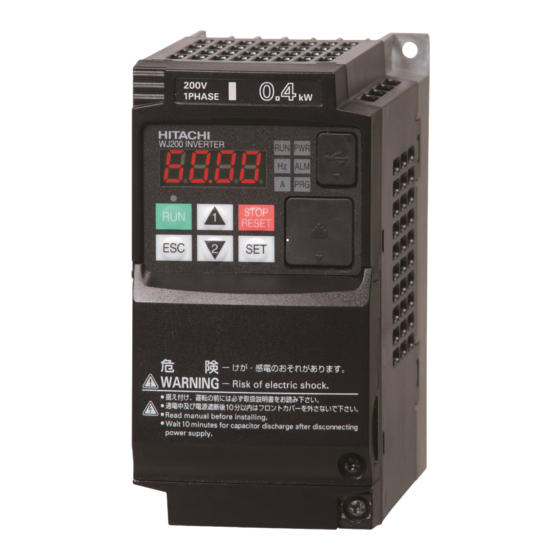
- Page 1 Pursuing the Ideal Compact Inverter Pursuing the Ideal Compact Inverter Series Designed for excellent performance and user friendliness...
- Page 2 Motor Current Output Frequency Output Frequency • Frequency commanded by the inverter: 0.5Hz. • Motor: Hitachi's standard 3-phase 5.5kW 4-pole totally enclosed type motor. * WJ200: 5min , Previous model: 13min *Turn off this function for lifting equipment. Model Name Indication...
- Page 3 Index Features P 2– 5 Simple positioning control (when feedback signal is used.) Standard Specifications When simple positioning function is activated, speed control operation or General Specifications positioning control operation is selectable via intellient input. While the [SPD] input is ON, the current position counter is held at 0. When [SPD] is OFF, the inverter enters positioning control operation and the position counter is active.
- Page 4 Sequence operation is realized by downloading to an inverter a WJ200 conforms to the applicable safety standards and corresponds program created with Hitachi's EzSQ software. User program can to Machinery Directive of Europe. Shuts down the inverter by be compiled on EzSQ software on a PC. External components can hardware, bypassing the CPU, to achieve reliable safe stop function.
- Page 5 Network compatibility External ports Easy to maintain & A serial RS485 Modbus/RTU port is standard. The WJ200 can Easy selection of displayed parameters communicate via DeviceNet and CCLink with optional expansion ● Data comparison function card. USB (Mini-B connector) port and RS422 (RJ45 connector) port Display parameters changed from default setting.
-
Page 6: Standard Specifications
11.5 *1: The applicable motor refers to Hitachi standard 3-phase motor (4p). When using other motors, care must be taken to prevent the rated motor current (50/60Hz) from exceeding the rated output current of the inverter. *2: The output voltage varies as the main supply voltage varies (except when using the AVR function). In any case, the output voltage cannot exceed the input power supply voltage. -
Page 7: General Specifications
*6: 1-phase 100V class is only with CT. *7: The frequency command is the maximum frequency at 9.8V for input voltage 0 to 10VDC, or at 19.6mA for input current 4 to 20mA. If this characteristic is not satisfactory for your application, contact your Hitachi representative. - Page 8 109 (4.29) 001LF, 002LF 004SF, 004LF 122.5 (4.82) 004MF 132.5 (5.22) 007LF 145.5 (5.73) • WJ200-110LF • WJ200-007MF • WJ200-007SF – 022SF • WJ200-110HF • WJ200-015LF, 022LF • WJ200-150HF 180 (7.09) • WJ200-004HF – 030HF Ø7 (0.28) 108 (4.25) Ø4.5 (0.18)
-
Page 9: Operation And Programming
Operation and Programming Operation Panel WJ200 Series can be easily operated with the digital operator provided as standard. ( 4 ) Run LED ( 1 ) POWER LED ON when inverter is in RUN mode. ON (Green) while the inverter is receiving input power. - Page 10 Terminal ( Arrangements / Functions Terminal Description Symbol Terminal Name Symbol Terminal Name R/L1, S/L2, T/L3 Main power supply input terminals P/+, RB External braking resistor connection terminals U/T1, V/T2, W/T3 Inverter output terminals P/+, N/- External braking unit connection terminals PD/+1, P/+ DC reactor connection terminals Ground connection terminal...
- Page 11 Hardware Switches a Termination resistor selection switch Switch Name Switch Name Description Termination resistor for the RS485 a Termination resistor selection switch communication port. (Default) WJ200 has a built-in 200Ω resistor activated by a DIP switch. b Safe stop function selection switch To enable the Safe stop function, set the b Safe stop function...
-
Page 12: Function List
Function List If a desired parameter is not displayed, check the setting of function "b037"(function code display restriction). To display all parameters, specify "00" for "b037". [ ○ = Allowed × = Not parmitted] Setting During Change During Default Code Function Name Setting Range Operation... - Page 13 [ ○ = Allowed × = Not parmitted] Setting During Change During Default Code Function Name Setting Range Operation Operation Setting (allowed or not) (allowed or not) A019 Multi-speed operation selection 00 (Binary mode) / 01 (Bit mode) × × A020 Multi-speed 0 setting 0.00 / "start frequency"...
- Page 14 Function List [ ○ = Allowed × = Not parmitted] Setting During Change During Default Code Function Name Setting Range Operation Operation Setting (allowed or not) (allowed or not) A085 Operation mode selection 00 (normal operation), / 01 (energy-saving operation) ×...
- Page 15 [ ○ = Allowed × = Not parmitted] Setting During Change During Default Code Function Name Setting Range Operation Operation Setting (allowed or not) (allowed or not) 00 (disabled) / 01 (enabled during acceleration and constant-speed operation) / b021 Overload restriction operation mode ×...
- Page 16 Function List [ ○ = Allowed × = Not parmitted] Setting During Change During Default Code Function Name Setting Range Operation Operation Setting (allowed or not) (allowed or not) 00 (starting with 0 Hz) / b088 Restart mode after FRS 01 (starting with matching frequency) / ×...
- Page 17 [ ○ = Allowed × = Not parmitted] Setting During Change During Default Code Function Name Setting Range Operation Operation Setting (allowed or not) (allowed or not) 00 (FW: Forward Run) / 01 (RV: Reverse RUN) / 02 (CF1: Multispeed 1setting) / 03 (CF2: Multispeed 2 setting) / 04 (CF3: Multispeed 3 setting) / C001 Terminal [1] function...
- Page 18 Function List Setting During Change During Default Code Function Name Setting Range Operation Operation Setting (allowed or not) (allowed or not) 115% of C041 Overload level setting Set range: 0 to 200% of inverter rated current [A] ○ ○ Rated current 115% of C241 Overload level setting, 2nd motor...
- Page 19 00 (disabled auto-tuning) / 01 (auto-tuning without rotation) / H001 Auto-tuning Setting × × 02 (auto-tuning with rotation) H002 Motor data selection × × 00 (Hitachi standard data) / 02 (auto-tuned data) H202 Motor data selection, 2nd motor × × H003 Motor capacity × × Factory set 0.1 / 0.2 / 0.4 / 0.55 / 0.75 / 1.1 / 1.5 / 2.2 / 3.0 / 3.7 / 4.0 / 5.5 / 7.5 / 11.0 / 15.0 / 18.5 [kW]...
- Page 20 Function List [ ○ = Allowed × = Not parmitted] Setting During Change During Default Code Function Name Setting Range Operation Operation Setting (allowed or not) (allowed or not) 00 (digital operator) / P031 Accel / decel time input selection ×...
-
Page 21: Protective Functions
Protective Functions Name Cause(s) Error Code Over-current event while at constant speed E01. The inverter output was short-circuited, or the motor shaft is locked or has a heavy load. Over-current event during deceleration E02. These conditions cause excessive current for the inverter, so the inverter output is turned OFF. Over-current event during acceleration E03. -
Page 22: Connecting Diagram
Connecting Diagram Source Type Logic R/L1 U/T1 S/L2 V/T2 T/L3 Power source, 24VDC W/T3 3-phase or 1-phase, Motor per inverter model Short bar Using source logic of Short bar external machine PD/+1 output and/or external Remove the jumper power supply, only when connecting please refer to P24. - Page 23 Sink Type Logic R/L1 U/T1 S/L2 V/T2 T/L3 Power source, 24VDC W/T3 3-phase or 1-phase, Motor Short bar per inverter model Short bar Using source logic of external machine output and/or external PD/+1 power supply, please refer to P24. Remove the jumper only when connecting the DCL.
- Page 24 Connection with Input Terminals Using Internal Power Supply of the Inverter Using External Power Supply (Please remove the short bar.) Short bar 24VDC 24VDC DC24V Hitachi EH-150 series PLC Hitachi EH-150 series PLC Output Module EH-YT16 Output Module EH-YTP16 Inverter Inverter 24VDC 24VDC...
- Page 25 Model Power Lines Signal Lines class J, 600V) ° – – WJ200-004MF AWG12/3.3mm C only) 1-phase 100V – 0.75 – WJ200-007MF AWG10/5.3mm ° C only) WJ200-001SF ° WJ200-002SF AWG16 / 1.3mm C only) 0.55 WJ200-004SF 1-phase 200V ° 0.75 WJ200-007SF AWG12 / 3.3mm...
-
Page 26: For Correct Operation
Therefore, carefully make selection and settings by checking the mechanical strength of the motor and connected machines. Consult the motor manufacturer when it is necessary to drive a standard (general-purpose) motor above 60 Hz. A full line of high-speed motors is available from Hitachi. - Page 27 [About the use in highlands beyond l,000m above sea level] When the standard inverter is used at a place beyond l,000m above sea level because it cool heating element with air, please be careful as follows, But please inquire for the highlands more than 2,500m separately.
- Page 28 Printed in Japan ( H ) SM-E265Q 1011...