Grizzly G0449 Owner's Manual
37" drum sander
Hide thumbs
Also See for G0449:
- Owner's manual (80 pages) ,
- Instruction manual (60 pages) ,
- Parts breakdown (10 pages)
Table of Contents
Advertisement
Quick Links
Download this manual
See also:
Instruction Manual
MODEL G0449/G0450
37" DRUM SANDER
OWNER'S MANUAL
(FOR MACHINES MANUFACTURED SINCE 8/13)
177335
COPYRIGHT © JUNE, 2005 BY GRIZZLY INDUSTRIAL, INC. REVISED SEPTEMBER, 2014 (BL)
WARNING: NO PORTION OF THIS MANUAL MAY BE REPRODUCED IN ANY SHAPE
OR FORM WITHOUT THE WRITTEN APPROVAL OF GRIZZLY INDUSTRIAL, INC.
#TREWPCBL7210 PRINTED IN TAIWAN
V4.09.14
Advertisement
Table of Contents

Related Manuals for Grizzly G0449


Summary of Contents for Grizzly G0449
- Page 1 (FOR MACHINES MANUFACTURED SINCE 8/13) 177335 COPYRIGHT © JUNE, 2005 BY GRIZZLY INDUSTRIAL, INC. REVISED SEPTEMBER, 2014 (BL) WARNING: NO PORTION OF THIS MANUAL MAY BE REPRODUCED IN ANY SHAPE OR FORM WITHOUT THE WRITTEN APPROVAL OF GRIZZLY INDUSTRIAL, INC.
- Page 2 This manual provides critical safety instructions on the proper setup, operation, maintenance, and service of this machine/tool. Save this document, refer to it often, and use it to instruct other operators. Failure to read, understand and follow the instructions in this manual may result in fire or serious personal injury—including amputation, electrocution, or death.
-
Page 3: Table Of Contents
G0449/G0450 Control Panel ....... 55 Power Connection........19 G0449 Electrical Box 240V ......56 Gear Oil Check ..........20 G0449 Electrical Box Wiring 240V ....57 Test Run ............20 G0449 Sanding & Feed Motors ....58 Recommended Adjustments ......22 G0450 Electrical Box 240V ...... -
Page 4: Introduction
We want your feedback on this manual. What did Serial Number you like about it? Where could it be improved? Please take a few minutes to give us feedback. Grizzly Documentation Manager P.O. Box 2069 Bellingham, WA 98227-2069 Email: manuals@grizzly.com Model G0449/G0450 (Mfd. Since 8/13) -
Page 5: G0449 Machine Data Sheet
MACHINE DATA SHEET Customer Service #: (570) 546-9663 · To Order Call: (800) 523-4777 · Fax #: (800) 438-5901 MODEL G0449 37" DRUM SANDER, 10 HP SINGLE-PHASE Product Dimensions: Weight................................1143 lbs. Width (side-to-side) x Depth (front-to-back) x Height..............68 x 50-1/2 x 49 in. - Page 6 The information contained herein is deemed accurate as of 8/15/2013 and represents our most recent product specifications. Model G0449 PAGE 2 OF 2 Due to our ongoing improvement efforts, this information may not accurately describe items previously purchased. Model G0449/G0450 (Mfd. Since 8/13)
-
Page 7: G0450 Machine Data Sheet
The information contained herein is deemed accurate as of 9/16/2013 and represents our most recent product specifications. Model G0450 PAGE 1 OF 2 Due to our ongoing improvement efforts, this information may not accurately describe items previously purchased. Model G0449/G0450 (Mfd. Since 8/13) - Page 8 The information contained herein is deemed accurate as of 9/16/2013 and represents our most recent product specifications. Model G0450 PAGE 2 OF 2 Due to our ongoing improvement efforts, this information may not accurately describe items previously purchased. Model G0449/G0450 (Mfd. Since 8/13)
-
Page 9: Identification
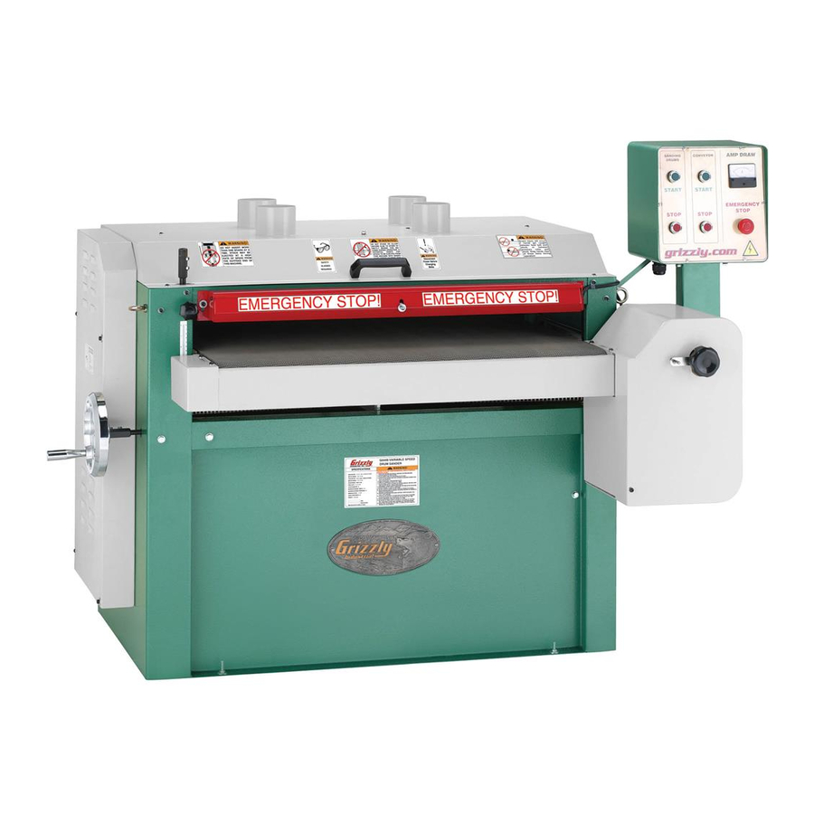
Identification Figure 1. Front view, Model G0449/G0450. M. Gas Strut A. Table Height Shaft N. Pressure Roller B. Table Height Handwheel O. Dust Port C. Depth Scale P. Emergency Stop Bar D. Lifting Hook Q. Micro-Adjust Knob (Right Side) E. Table Height Lock Knob R. -
Page 10: Section 1: Safety
Everyday ery. Never operate under the influence of drugs or eyeglasses are NOT approved safety glasses. alcohol, when tired, or when distracted. Model G0449/G0450 (Mfd. Since 8/13) - Page 11 Contact our debris. Make sure they are properly installed, Technical Support at (570) 546-9663. undamaged, and working correctly. Model G0449/G0450 (Mfd. Since 8/13)
-
Page 12: Additional Safety For Drum Sanders
If normal safety respect. Failure to do so could result in precautions are overlooked or ignored, serious personal injury, damage to equip- serious personal injury may occur. ment, or poor work results. -10- Model G0449/G0450 (Mfd. Since 8/13) -
Page 13: Section 2: Power Supply
G0449 Amp Draw at 240V ....47 Amps G0450 Amp Draw at 240V ....43 Amps Acceptable Voltage Range .....216V–264V G0450 Amp Draw at 480V ....21.5 Amps Cycle ............60 Hz... -
Page 14: Grounding Instructions
(see Conduit Conduit Page 19 for instructions). DO NOT use a static phase converter, as they notoriously damage Ground Ground electrical components. Figure 2. Typical setup of a permanently connected machine. -12- Model G0449/G0450 (Mfd. Since 8/13) -
Page 15: 480V Conversion
The G0450 480V Conversion Kit (Part Number P0450753), which includes the necessary 480V main panel, can be purchased by calling Grizzly Customer Service at (800) 523-4777. All wiring changes must be performed by an elec- trician or qualified service personnel. If, at any time during this procedure you need help, call Grizzly Tech Support at (570) 546-9663. -
Page 16: Section 3: Setup
When you are completely satisfied with the condi- followed. To be safe, tion of your shipment, inventory the contents. get assistance and use power equipment when moving the crate and removing the machine from the crate. -14- Model G0449/G0450 (Mfd. Since 8/13) -
Page 17: Inventory
-15- Model G0449/G0450 (Mfd. Since 8/13) -
Page 18: Assembly
Figure 9. The threaded end of each strut should be flush with the outside Figure 10. Control panel mounting bolts. of the bracket. Remove the right access panel to gain access for attaching the control panel support arm. -16- Model G0449/G0450 (Mfd. Since 8/13) -
Page 19: Placing Sander
Figure 13. Figure 12. Handwheel installed. Figure 13. Lifting the sander. Lift the sander and move it to your predeter- mined location. DO NOT lift it any higher than is necessary to clear the floor. -17- Model G0449/G0450 (Mfd. Since 8/13) -
Page 20: Mounting To Floor
Dust Collection Anchor Stud DO NOT operate the Model G0449/G0450 without an adequate dust collection system. This sander creates substantial amounts of wood dust while operating. Failure to use a... -
Page 21: Power Connection
Wire Figure 16. Dust port locations. Connect Incoming Hot Wires Here Power Connection Figure 17. G0449 junction box wiring. Note (Model G0450 Only): When using a Before connecting to power, read through the phase converter, connect the manufactured SECTION 2: CIRCUIT REQUIREMENTS section power leg or "wild wire"... -
Page 22: Gear Oil Check
Make sure the feed motor gearbox is full of oil and the shipping seal is removed from the vented fill plug. Ensure all tools and objects used during setup are cleared away from the machine, and all covers and panels are closed. -20- Model G0449/G0450 (Mfd. Since 8/13) - Page 23 Clockwise Swap These Connections Figure 21. Swapping L1 and L3 wires at Figure 20. Resetting the switch. incoming power junction box. Model G0449: Press the CONVEYOR START Press the CONVEYOR STOP button to stop button. the machine. — If problems...
-
Page 24: Recommended Adjustments
Step-by-step instructions for these adjust- ments can be found in the SERVICE section. V-Belt Tension (Page 36). Perform after the first 16 hours. Conveyor Tensioning & Tracking (Page 40). Drum Adjustments (Page 41). Pressure Roller Height (Page 46). -22- Model G0449/G0450 (Mfd. Since 8/13) -
Page 25: Section 4: Operations
Conveyor Stop training before beginning any projects. Stop Button Button Regardless of the content in this section, Figure 22. Control panel. Grizzly Industrial will not be held liable for accidents caused by lack of training. -23- Model G0449/G0450 (Mfd. Since 8/13) -
Page 26: Operation Overview
A variable speed knob allows the operator to adjust the conveyor speed for the specific type of workpiece and finish stage. -24- Model G0449/G0450 (Mfd. Since 8/13) -
Page 27: Stock Inspection And Requirements
Always visually inspect your workpiece 2" Min. for these items. If they can't be removed, DO NOT sand the workpiece. Figure 24. Minimum dimensions for sanding. -25- Model G0449/G0450 (Mfd. Since 8/13) -
Page 28: Depth Of Cut
SLOWLY raise the conveyor table until the workpiece makes light contact with the sanding drums. This is the correct height to begin sanding the workpiece. Variable Speed Knob Figure 26. Variable speed knob. -26- Model G0449/G0450 (Mfd. Since 8/13) -
Page 29: Using The Amp Draw Meter
Depth of Cut on Page 26. grit, and workpiece width. Start the dust collector, the drum motor, and G0449 Maximum Amp Load ....... 47A the feed motor. G0450 Maximum Amp Load at 240V ..43A G0450 Maximum Amp Load at 480V ..21.5A... -
Page 30: Sanding Tips
The Model G0449/G0450 allows you to place a different grit sandpaper on each drum. The • DO NOT edge sand boards. This can cause... -
Page 31: Paper Replacement
Paper Replacement 17" The Model G0449/G0450 is designed for 6" wide 6" sandpaper rolls. 17" To change the paper: 138" DISCONNECT POWER TO SANDER! Grit Side Up Lift the top cover and place a screwdriver Figure 31. Sandpaper pattern. through the right side of the frame and into the side of the drum, as shown in Figure 30. -
Page 32: Section 5: Accessories
Carry a Power Twist V-Belt in your vehicle for a fix any- ® where solution to broken fan belts. Figure 33. Half-mask respirator with disposable cartridge filters. Figure 35. Power Twist V-Belt. ® -30- Model G0449/G0450 (Mfd. Since 8/13) -
Page 33: Section 6: Maintenance
Damaged V-belts. Figure 37). • Any other unsafe condition. Cleaning Cleaning the Model G0449/G0450 is relatively easy. From time to time vacuum wood dust off of the internal components, especially the motor. Lubrication Moving parts such as chains should be lubricated Figure 37. - Page 34 We recommend you create a checklist for routine inspection and maintenance. Remember to always disconnect the drum sander from its power source before attempting to inspect, adjust, or repair this machine! -32- Model G0449/G0450 (Mfd. Since 8/13)
-
Page 35: Section 7: Service
2. Power supply switched OFF or is at fault. 2. Ensure power supply is switched on; ensure power supply has the correct voltage. 3. Start capacitor is at fault (G0449 only). 3. Test/replace if faulty (G0449 only). 4. Motor connection wired incorrectly. - Page 36 2. Too much pressure from rear pressure 2. Reduce rear pressure roller pressure (Page 46). rollers. 3. Lack of outfeed support. 3. Set up outfeed table or have someone catch the workpiece as it comes out. -34- Model G0449/G0450 (Mfd. Since 8/13)
- Page 37 Y into 4" at the machine. 2. Dust collector underpowered or too far 2. Upgrade your dust collector or decrease the away from this machine. distance from the dust collector to the machine. -35- Model G0449/G0450 (Mfd. Since 8/13)
-
Page 38: Gauge Blocks
Then cut the 2x4 into two even pieces to make two 36" long wood gauge blocks. Figure 43. Checking V-belt tension with a straightedge and a ruler. -36- Model G0449/G0450 (Mfd. Since 8/13) -
Page 39: Pulley Alignment
Pulley Alignment Pulley alignment is another important factor in power transmission and belt life. The pulleys should be parallel to each other and in the same plane (coplaner) for optimum performance. -37- Model G0449/G0450 (Mfd. Since 8/13) -
Page 40: Bearing Replacement
Clean and inspect the drum shaft for cracks, burrs, wear, and other damage; replace/ repair as required. The Model G0449/G0450 is designed for many years of reliable service. But after long periods Use a screwdriver to pry and rotate the bear-... - Page 41 Make sure the bearing grease hole in the bearing lines up with the grease groove in the bearing housing and that no obstructions prevent bearing lubrication. Bearing Screw Grease Port Bearing Guide Pin Race Figure 50. Key bearing parts -39- Model G0449/G0450 (Mfd. Since 8/13)
-
Page 42: Conveyor Tensioning & Tracking
" To tension the conveyor: Figure 52. Conveyor belt hanging gap. Using a 19mm wrench, loosen the lock nut (see Figure 51) on both sides of the con- veyor. -40- Model G0449/G0450 (Mfd. Since 8/13) -
Page 43: Drum Adjustments
— If the conveyor tracks too far to the other side, then adjust the bolt as necessary to Feed Direction bring it back and repeat Steps 2 & 3 until Figure 53. Drum perpendicular to feed direction. the tracking is correct. -41- Model G0449/G0450 (Mfd. Since 8/13) - Page 44 ⁄ ", skip to distance between the rear upper frame angle Step 8. and drum is within ⁄ " at each end, then tight- en the rear drum pillow bearing lock nuts. -42- Model G0449/G0450 (Mfd. Since 8/13)
- Page 45 10. Place the small gauge blocks on each end of the pressure roller between both drums as shown in Figure 57. Gauge Blocks Figure 57. Example of small gauge block positioned between front and rear drums. -43- Model G0449/G0450 (Mfd. Since 8/13)
- Page 46 To adjust the rear drum height and adjust the adjusting knob. drums parallel to the conveyor belt: DISCONNECT POWER TO SANDER! Open the top and pulley covers, remove the V-belts, and remove sandpaper from the drums for best results. -44- Model G0449/G0450 (Mfd. Since 8/13)
- Page 47 V-belts, and Lock the micro-adjustment lock lever and close the pulley and top covers. lock handle. Loosen the front drum pillow bearing lock nuts (Figure 55, Page 43). -45- Model G0449/G0450 (Mfd. Since 8/13)
-
Page 48: Pressure Roller Height
2) repeat with the other side; 3) tighten the lock nuts together to make sure the adjustments are locked in place. -46- Model G0449/G0450 (Mfd. Since 8/13) -
Page 49: Scale Pointer Calibration
Cap Screw Scoop Plate Figure 66. Location to adjust dust scoop. Adjust each scoop in this manner until the sanding drums do not scrape the scoops, then close the pulley cover and reinstall the handwheel. -47- Model G0449/G0450 (Mfd. Since 8/13) -
Page 50: Table Lift Screws
Page 47). shown in Figure 67. 11. Follow instructions in Drum Adjustments (Refer to Page 41) for adjusting the drums parallel to the conveyor within 0.002" side-to- side. -48- Model G0449/G0450 (Mfd. Since 8/13) -
Page 51: Conveyor Belt Replacement
DISCONNECT POWER TO SANDER! Remove the top cover (6 button head screws), table height handwheel, and open the pulley cover. Figure 70. Gauge blocks set under pressure rollers to relieve spring tension with the table. -49- Model G0449/G0450 (Mfd. Since 8/13) - Page 52 14. Loosen the conveyor belt from the rear adjustments, as shown in Figure 73. Figure 71. Drum sander disassembled to Step 11. Figure 73. Conveyor belt loosened at the rear adjustment. -50- Model G0449/G0450 (Mfd. Since 8/13)
- Page 53 (part #378 in the breakdown drawing), as they can be easily knocked onto the ground. Figure 75. Lifting the table off of the drum sander cabinet with four people. -51- Model G0449/G0450 (Mfd. Since 8/13)
-
Page 54: Section 8: Wiring
The photos and diagrams included in this section are best viewed in color. You can view these pages in color at www.grizzly.com. -52- Model G0449/G0450 (Mfd. Since 8/13) -
Page 55: G0449/G0450 Wiring Overview
MOTOR ELECTRICAL BOX G0449, see Page 58 G0450, see Page 63 G0449 @ 240V, see Pages 56 & 57 G0450 @ 240V, see Pages 59 & 60 FEED MOTOR G0450 @ 480V, see Pages 61 & 62 G0449, see Page 58... -
Page 56: G0449 Junction Box
G0449 Junction Box To Electrical Box Pages 56 & 57 1-PHASE 240 VAC DISCONNECT SWITCH (as recommended ) Figure 78. G0449 power junction box. G0450 Junction Box To Electrical Box Pages 59, 60, 61 & 62 3-PHASE 240/480 VAC DISCONNECT... -
Page 57: G0449/G0450 Control Panel
G0449 240V 3-Ph, Page 60 G0450 480V 3-Ph, Page 62 Emergency Conveyor Drum STOP STOP STOP Switch Switch Switch Figure 80. G0449/G0450 control panel wiring. Figure 81. G0449/G0450 control panel. READ ELECTRICAL SAFETY -55- Model G0449/G0450 (Mfd. Since 8/13) ON PAGE 52! -
Page 58: G0449 Electrical Box 240V
G0449 Electrical Box 240V Figure 82. G0449 electrical box. READ ELECTRICAL SAFETY -56- Model G0449/G0450 (Mfd. Since 8/13) ON PAGE 52! -
Page 59: G0449 Electrical Box Wiring 240V
G0449 Electrical Box Wiring 240V 13 NO 43 NO 13NO 21 NO 31 NO TECO CU-11 TECO CU-50 220V Coil 32 NO 22 NO 14NO 220V Coil 14 NO 44 NO TECO RHU-10K1 TRIP IND. CURRENT TECO RHU-80K3 SENSOR TEST TRIP IND. -
Page 60: G0449 Sanding & Feed Motors
Figure 83. G0449 sanding drum motor Start Capacitor wiring and start capacitors. 300MFD Ground 250VAC To Electrical Box Figure 87. G0449 sanding drum motor, 240V single-phase. Figure 84. G0449 sanding drum motor run capacitors. Start Capacitor 75MFD 125VAC Figure 85. G0449 feed motor wiring. -
Page 61: G0450 Electrical Box 240V
G0450 Electrical Box 240V Figure 89. G0450 240V 3-phase electrical box wiring. READ ELECTRICAL SAFETY -59- Model G0449/G0450 (Mfd. Since 8/13) ON PAGE 52! -
Page 62: G0450 Electrical Box Wiring 240V
PANEL TERMINAL BLOCK Feed Emerg. Sanding Junction Box Motor Stop Bar Drum Control Figure 79 Figure Limit Switch Motor Panel Figure 77 Figure 91 Figures 80 & 81 READ ELECTRICAL SAFETY -60- Model G0449/G0450 (Mfd. Since 8/13) ON PAGE 52! -
Page 63: G0450 Electrical Box 480V
G0450 Electrical Box 480V Figure 90. G0450 480V 3-phase electrical box wiring. READ ELECTRICAL SAFETY -61- Model G0449/G0450 (Mfd. Since 8/13) ON PAGE 52! -
Page 64: G0450 Electrical Box Wiring 480V
BLOCK To Sanding Feed Emerg. Drum Motor Stop Bar Junction Box Motor Control Panel Figure 94 Limit Switch Figure 79 Figure 91 Figures 80 & 81 Figure 77 READ ELECTRICAL SAFETY -62- Model G0449/G0450 (Mfd. Since 8/13) ON PAGE 52! -
Page 65: G0450 Sanding Drum Motor
W1 W5 (additional conversions required for 440V operation) (additional conversions required for 480V operation) To Electrical Box G0450 240V 3-Phase Page 60 or G0450 480V 3-Phase Page 62 READ ELECTRICAL SAFETY -63- Model G0449/G0450 (Mfd. Since 8/13) ON PAGE 52! -
Page 66: G0450 Feed Motor
240V 480V MOTOR MOTOR (additional conversions required for 480V operation) To Electrical Box G0450 240V 3-Ph, Page 60 or G0450 480V 3-Ph, Page 62 READ ELECTRICAL SAFETY -64- Model G0449/G0450 (Mfd. Since 8/13) ON PAGE 52! -
Page 67: Section 9: Parts
SECTION 9: PARTS Frame G0450 440V Conversion Kit (Replaces Part #553) 553-1 553-2 506V2 553-3 311-1 311-4 380-2 311-3 311-2 311-6 380-1 311-5 509V2 380-3 311-9 311-8 311-10 311-7 317-1 350-1 524-1 381-1 381-2 -65- Model G0449/G0450 (Mfd. Since 8/13) - Page 68 Please Note: We do our best to stock replacement parts whenever possible, but we cannot guarantee that all parts shown here are available for purchase. Call (800) 523-4777 or visit our online parts store at www.grizzly.com to check for availability.
- Page 69 553-1 P0449553-1 SANDING MOTOR CORD 10G 4W 98" P0449581 EXT TOOTH WASHER 5/16 553-2 P0449553-2 FEED MOTOR CORD 14G 3W 79" P0449582 HEX NUT 5/16 553-3 P0449553-3 CORD 16G 2W 98" P0449753 480V CONVERSION KIT (G0450) -67- Model G0449/G0450 (Mfd. Since 8/13)
-
Page 70: Conveyor
Conveyor -68- Model G0449/G0450 (Mfd. Since 8/13) - Page 71 P0449438-4 S CAPACITOR 75M 125V (G0449) P0449395 HEX BOLT M12-1.75 X 80 438-5 P0449438-5 CAPACITOR COVER P0449396 HEX NUT M12-1.75 438-6 P0449438-6 R CAPACITOR 20M 300V 1-5/16 X 2 (G0449) P0449397 OUTFEED ROLLER 438-7 P0449438-7 MOTOR JUNCTION BOX (G0449) 397-1 P0449397-1 OUTFEED ROLLER SHAFT...
-
Page 72: Roller & Drum
EXTENSION SPRING P0449500 ROLLER BUSHING SUPPORT P0449486 BUTTON HD CAP SCR M6-1 X 12 P0449501 EXT RETAINING RING 19MM P0449487 FLAT WASHER 6MM P0449502 ROLLER COMPRESSION SPRING P0449488 PILLOW BEARING UCP206 P0449551 SPRING TENSION TOOL -70- Model G0449/G0450 (Mfd. Since 8/13) -
Page 73: Micro-Adjust
SET SCREW 10-24 X 1/4 P0449624 SET SCREW 1/4-20 X 5/16 P0449611 HEX NUT 10-24 P0449625 HEX NUT 5/16-18 P0449612 DUST COVER P0449626 FLAT WASHER 5/16 P0449613 TAP SCREW #10 X 3/8 P0449627 LOCK HANDLE -71- Model G0449/G0450 (Mfd. Since 8/13) -
Page 74: Electrical
741V2 440V Conversion Kit, G0450 only L1/1 L2/3 L3/5 R/1/L1 T/5/L3 S/3/L2 FEED MOTOR CONTACTOR SANDING DRUM 742A CONTACTOR 744A 440V Coil 440V Coil T1/2 T2/4 T3/6 745AV2 U/2/T1 V/4/T2 W/6/T3 743A 755A 741V2 -72- Model G0449/G0450 (Mfd. Since 8/13) - Page 75 742AV2 P0450742AV2 CONTACTOR TECU CU-40 440V (G0450 480V) 755A P0450755A ELECTRICAL PANEL (G0450 480V) 743V2 P0449743V2 OL RELAY TECO RHU-80K3 (G0449, G0450 240V) P0449756 CONTROL PANEL PLATE 743AV2 P0450743AV2 OL RELAY TECO RHU-80K2 (G0450 480V) 759V2 P0449759V2 ANALOG AMP METER 100/5A V2.11.13...
-
Page 76: Label Placement
Safety labels help reduce the risk of serious injury caused by machine hazards. If any label comes off or becomes unreadable, the owner of this machine MUST replace it in the original location before resuming operations. For replacements, contact (800) 523-4777 or www.grizzly.com. -74-... - Page 77 Would you recommend Grizzly Industrial to a friend? _____ Yes _____No Would you allow us to use your name as a reference for Grizzly customers in your area? Note: We never use names more than 3 times. _____ Yes _____No 10.
- Page 78 FOLD ALONG DOTTED LINE Place Stamp Here GRIZZLY INDUSTRIAL, INC. P.O. BOX 2069 BELLINGHAM, WA 98227-2069 FOLD ALONG DOTTED LINE Send a Grizzly Catalog to a friend: Name_______________________________ Street_______________________________ City______________State______Zip______ TAPE ALONG EDGES--PLEASE DO NOT STAPLE...
-
Page 79: Warranty And Returns
WARRANTY AND RETURNS Grizzly Industrial, Inc. warrants every product it sells for a period of 1 year to the original purchaser from the date of purchase. This warranty does not apply to defects due directly or indirectly to misuse, abuse, negligence, accidents, repairs or alterations or lack of maintenance.