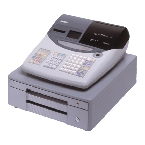
Casio TE-2000 Service Manual
Hide thumbs
Also See for TE-2000:
- User manual (88 pages) ,
- Operation manual (16 pages) ,
- Service manual (3 pages)

Related Manuals for Casio TE-2000


Summary of Contents for Casio TE-2000
- Page 1 SERVICE MANUAL (without price) ELECTRONIC CASH REGISTER TE-2000 (EX-273) MAR. 2002 Ver. 3 OCT. / 2002 Ver. 2 AUG. / 2002 INDEX Ver. 1 APR. / 2002...
-
Page 2: Table Of Contents
CONTENTS TE-2000 PAGE 1. SPECIFICATIONS ..................1 2. INITILAIZE OPERATION ................3 3. BLOCK DIAGRAM ..................4 4. DISASSEMBLY .................... 5 5. CIRCUIT EXPLANATIONS ............... 16 6. DIAGNOSTIC OPERATION ............... 21 7. ERROR CODE LIST................... 28 8. IC DATA ..................... 29 9. -
Page 3: Specifications
1. SPECIFICATIONS 1-1. Electrical Specifications •Power consumption 120V 220V 230V 240V In operationMax. 0.65A 0.35A 0.35A 0.35A Stand-by Max. 0.3A 0.2A 0.2A 0.2A •Memory protection Back-up battery Mangan battery (R6,UM-3) Back-up period 1 year (25 °C) Battery life Replace the battery every year. •Clock &... - Page 4 1-5. Option List DEVICE NAME MODEL NOTE •PC cable PRL-CB-2 •Sheet cover WT-82 •Roll paper P-5880T CAUTION ! Danger of explosion if battery is incorrectly replaced. Replace only with the same or equivalent type recommended by the manufacturer. Dispose of used batteries according to the manufacture’s instructions.
-
Page 5: Initilaize Operation
2. INITIALIZE OPERATION Initializing the cash register • Automatic initialization Use the following procedure to initialize the cash register before using it for the first time after you purchase it. 1. Install the three memory backup batteries (see page 7 of the User's Manual). 2. -
Page 6: Block Diagram
3. BLOCK DIAGRAM Pop-up Display E272-E2-2 8 pin 12 pin 8 pin 12 pin Character Display Winder Motor Main Display 28 pin 28 pin Printer Printer E272-E2-1 E272-PR E272-PR 30 pin 30 pin 30 pin 30 pin 30 pin 30 pin 3 pin 4 pin 28 pin... -
Page 7: Disassembly
4. DISASSEMBLY UPPER COVER 1. Remove the printer cover. 1 Remove one screw. 2 Slide the DISPLAY PANEL in the direction of the arrow and remove the hook. 3 Slide the DISPLAY PANEL and lift it up. 4 Remove two FPCs (CN103, CN104). 4 Remove the DISPLAY UNIT. - Page 8 1 Remove two screws. 2 Slide the KEY UNIT to front side and lift it up. Then remove one FPC (CN13). Screws CN13 PRINTER UNIT 1. Remove the upper cover as shown in steps 1 to 3 of page 5. 2.
- Page 9 5. Remove one FPC (CN2). 6. Remove four screws and two connectors (CN9, CN10). Screws CN10 7. Removing the PRINTER UNIT 1 Remove five screws. 2 Remove the joint PCB. 3 Remove the PRINTER UNIT while pressing two hooks as shown in the figure. Screws opposite side Hook...
- Page 10 MAIN DISPLAY 1. Remove the upper cover as shown in steps 1 to 3 of page 5. 2. Remove two FPCs (CN101, CN102). 3. Remove four hooks and the MAIN DISPLAY. Hooks CN101 CN102 POWER SUPPLY UNIT 1. Remove the upper cover as shown in steps 1 to 3 of page 5. 2.
- Page 11 6. Remove the core. Core MAIN PCB 1. Remove the upper cover as shown in steps 1 to 3 of page 5. 2. Remove two screws and eight connectors (CN3-CN10) and then the MAIN PCB. CN10 Screws Removing the Drawer 1.
- Page 12 DRAWER (S type DRAWER) 1. Remove the upper tray. 2. Remove the lower drawer. 1 Push the lever in the direction of the arrow and pull out the lower tray. 2 Pull up the drawer. 3. Remove the top cover. 2 Remove the top cover by sliding it in the direction of the arrow.
- Page 13 4. Remove the UPPER COVER. 2 Open the case to some extent and remove the UPPER 1 Remove two screws. COVER by lifting it up. 1 Remove two screws and then the SOLENOID. 2 Remove the SPRING. Screws 3 Remove the hook lever by removing its stopper from the bottom surface. —...
- Page 14 6. Remove the screw and the roller. — 12 —...
- Page 15 DRAWER (M type DRAWER) 1. Remove the lower tray. 1 Push the lever in the direction of the arrow and pull out the lower tray. 2 Remove the COIN CASE. 3 Remove the BILL CASE. 4 Remove the tray. 2. Remove the upper iron plate. 1 Pull out the upper tray.
- Page 16 3. Remove the UPPER COVER. 1 Remove four screws. 2 Open the case to some extent and remove the UPPER COVER by lifting it up. Screws 4. Remove the upper tray. 5. Remove four screws and then RAIL MLED X 2. Screws 6.
- Page 17 7. Remove the UPPER COVER. 1 Remove two screws and the SOLENOID. 2 Remove the SPRING. Screws — 15 —...
-
Page 18: Circuit Explanations
5. CIRCUIT EXPLANATION 5-1. POWER SUPPLY CIRCUIT The power supply circuit provides the following voltage for the main circuit. Output Pin No. 1 (DC20~31V) For the drawer. Output Pin No. 2 (DC5V) For the logic circuit power. Output Pin No. 3 (DC8V) For the printer. - Page 19 RESET signal DATA BUS (AD2) H_UP (R) H-UP signal for Printer DATA BUS (AD3) H_UP (J) H-UP signal for Printer (TE-2000 only) DATA BUS (AD4) MT_IRQ MT_IRQ (from GATE Array) DATA BUS (AD5) Power supply status signal DATA BUS (AD6)
- Page 20 5-3. GATE ARRAY (IC15) Pin description PIN NO PIN NAME I / O D E S C R I P T I O N PIN NO PIN NAME I / O D E S C R I P T I O N ADDRESS (A4) MTR_1R MTR_R1 by Printer circuit...
- Page 21 Power supply GND: 5-5. FLASH ROM (IC18) This FROM is unable to write the application software from the PC. Therefore, Casio Techno will supply the FROM of the application software installation completion. A0 ~ A17: ADDRESS D0 ~ D7: DATA...
- Page 22 5-6. RS232C CIRCUIT The COM1 circuit is as follows: 5-7. BATTERY CIRCUIT The following shows the low battery indicator. Note: This message is a appeared when the battery became 3 or less volts. The BATTERY circuit is as follows: Japan only Japan only —...
-
Page 23: Diagnostic Operation
6. DIAGNOSTIC OPERATION TE-2000 enters the TEST mode by the following operation. a) Insert the mode key marked “PGM” into the mode switch. b) Turn the mode switch to the OFF position. c) While holding down the FEED button, turn the mode swich to the PGM positiion. - Page 24 Paper END sensor 0 : With paper 1 : No receipt paper 2 : No journal paper (only TE-2000) 3 : No receipt and journal paper (only TE-2000) Drawer sensor 1 : open (HIGH) 0 : closed (Low) (0 is displayed without the sensor)
- Page 25 Function Test By pressing numeric (0~9) + <#–2 (SUB TOTAL)>, various tests are performed. At this time, the following codes are printed. All Tests Operation : #–2 SUBTOTAL The above operation automatically does the following procedures. (All lit display, checking EPROM CHECK SUM, RAM test, time and date setting, drawer open, printing, issuing receipt) X :0 (or abbreviated) ..
- Page 26 Error procedure When the result of the ROM test occurs CHECK SUM ERROR in 2) ROM CHECK, sound the error buzzer, print the following and end the test. xxxx = CHECK SUM value ROM ER xxxx Issuing receipt When the result of the RAM test occurs error, sound the error buzzer, print the following and end the test. yy : xxxx = Error address RAM 128KB ER yy:xxxx...
- Page 27 FLASH ERASE TEST of FLASH ROM ..ERASE TEST for FLASH ROM (user area) is performed. Operation : #–2 SUBTOTAL [Plint format] When normally ended Issuing receipt FLASH ERASE OK [Plint format] When ended with an error yy : xxxx = Error bank : address Issuing receipt FLASH ERASE ER YY:XXXX...
- Page 28 RS232C Port Test ........L oop back test for RS232C Operation : #–2 SUBTOTAL The roop back test for RS232C port is performed by the connection shown below. 2 Pin 3 Pin 6 Pin Test contents (1) HI/LOW level reception check of DSR line (2) Sending data (OA5h) to Tx D line, receiving the same data from Rx D line The above (1) is checked once when the test starts.
- Page 29 Time display test Operation : #–2 SUBTOTAL X : 0 (or abbreviated) ... Time is displayed. 1 ......The time (23 hours 59 minutes and 50 seconds) is set. This operation continue the time display until the input of the clear button or power failure. [Print image] –...
-
Page 30: Error Code List
7. ERROR CODE LIST Errors are indicated by an error tone. When this happens, you can usually find out what the problem is as shown below. Error code Meaning Action (Message) Mode switch position changed before Retum the mode switch to its original setting finalization. -
Page 31: Ic Data
8. IC DATA 1. BA10339 (IC6,8) OUT2 OUT3 OUT1 OUT4 – – –IN1 +IN4 +IN1 –IN4 –IN2 +IN3 – – –IN +IN2 –IN3 2. BA10393F-E2(IC7) 4. UMA0206(UN206) (IC1,2,3,4) OUT1 –IN1 OUT2 – +IN1 –IN2 – +IN2 3. HIN202CBN (IC5) — 29 —... -
Page 32: Pcb Layout
9. PCB LAYOUT (Front side) Q29 Q28 IC18 39 38 37 CN12 C62 C66 IC17 IC11 IC10 R145 IC16 IC13 R137 IC14 R136 CM6 CM5 RM10 IC15 R143 CN13 — 30 —... - Page 33 (Back side) C30 C31 C28 C29 R118 R113 R116 R117 R115 R111 R114 R112 R108 R109 R107 R110 R105 R104 R122 R102 R123 R101 R124 R106 R125 R103 R100 R126 R127 R128 R129 R138 R158 R121 R130 R120 R119 R131 R132 R133 R134...
-
Page 34: Circuit Diagrams
10. CIRCUIT DIAGRAM MODEL : TE-2000 (EX-273) CONTENTS 1. OPTION BLOCK DIAGRAM ....................33 2. MAIN PCB CIRCUIT ........................ 34 2-1. MAIN PCB CIRCUIT (1/4) ....................34 2-2. MAIN PCB CIRCUIT (2/4) ....................35 2-3. MAIN PCB CIRCUIT (3/4) ....................36 2-4. - Page 35 — 33 —...
- Page 36 — 34 —...
- Page 37 — 35 —...
- Page 38 — 36 —...
- Page 39 — 37 —...
- Page 40 — 38 —...
- Page 41 — 39 —...
- Page 42 — 40 —...
- Page 43 — 41 —...
- Page 44 — 42 —...
- Page 45 — 43 —...
- Page 46 — 44 —...
-
Page 47: Parts List
2. As for spare parts order and supply, refer to the “GUIDEBOOK for Spare Parts Supply”, published separately. 3. The numbers in item column corespond to the same numbers in drawing. 4. CASIO does not supply the spare parts without parts code. 5. Remarks Q'ty :... -
Page 48: Explode View
— 46 —... - Page 49 23 ~ 34 23 ~ 34 — 47 —...
-
Page 50: Main Pcb Block
TE-2000 Q'ty Item Parts Name Specification Price Code No. Germany Other Rank Code 1. MAIN PCB BLOCK 1 10078667 PCB ASSY/E273-1 E240844*1 1 10083034 PCB ASSY/E273-1 E240844*3 N IC14 10077136 LSI UPD780053GC093-8BT N IC15 10071200 LSI UPD65884GM-032-8ED N IC1-4 10072557 IC... -
Page 51: Main Display Pcb Block
Q'ty Item Code No. Parts Name Specification Germany Other Price Rank Code R60,63,64 RESISTOR/CHIP RC1608-563-J-T N R20 10085157 RESISTOR/METAL OXIDE ERG-1SJ390 26050826 RESISTOR/METAL OXIDE ERG-1SJ5R6 CAPACITOR/CHIP UMK107CH120JZ-T C14-18,32-37,40 CAPACITOR/CHIP TMK107F104ZZ-T C6,11,19,39,41 CAPACITOR/CHIP UMK107CH101JZ-T CAPACITOR/CHIP UMK107CH150JZ-T C13,28-31 CAPACITOR/CHIP UMK212BJ104KG-T C8,9,38 CAPACITOR/CHIP TMK107B222KZ-T CAPACITOR/CHIP RV-50V101MH10-R... -
Page 52: Button Block
Item Code No. Parts Name Specification Q'ty Price Rank Code 9 10080402 SHEET RJE500003-1 10080403 CUSHION RJE500004-1 4. Button block 10 10072604 FLAME/KEY E140462-1 11 10072605 SHEET/FPC E240821-1 12 10072606 SPACER E341247-1 13 10072607 SHEET/COMMON E341246-1 14 10072608 CHASSIS/BUTTON E341248-1 15 10072609 KEYTOP/S E341250-1 16 62464030 KEYTOP/L... -
Page 53: Others
80 10072547 PULLY/WIND E240814-1 81 10079266 SPOOL/PAPER E341312-1 82 10080666 COVER/BATTERY E311096-4 83 10083676 CORE/FERRITE RT18X6X10 8. Other 84 62464000 KEY SET SUB ASSY E312046*2 85 10078829 NAME PLATE/TE-2000 E341307-5 Q'ty Item Code No. Parts Name Specification Europe Other Countries Price Rank... -
Page 54: Drawer (Dl-2778)
10. DRAWER (DL-2778) 22 27 — 52 —... - Page 55 DL-2778(M type) Europe, UK, Other countries Item Code No. Parts Name Specification Qt'y Price Rank code 1. MAIN CASE BLOCK 1 10078897 CASE/MAIN E140494-1 2 55000619 ROLLER/DELRIN DR-19B1 3 10079066 NUT 6 ZMC-3 4 10078764 LEVER/HOOK E341286-1 5 10078754 AXIS/HOOK LEVER E341241-1 SCREW 3X8 ZMC-3...
-
Page 56: Drawer (Dl-2779)
11. DRAWER (DL-2779) 24 29 — 54 —... - Page 57 DL-2779(M type) UK, Germany, Other countries Item Code No. Parts Name Specification Qt'y Price Rank code 1. MAIN CASE BLOCK 1 10078897 CASE/MAIN E140494-1 2 55000619 ROLLER/DELRIN DR-19B1 3 10079066 NUT 6 ZMC-3 4 10078764 LEVER/HOOK E341286-1 5 10078754 AXIS/HOOK LEVER E341241-1 SCREW 3X8 ZMC-3...
- Page 58 Correction of page 1, page 46 and page 50. Ver. 2 : Correction of page 1 and page 16. Ver. 3 : Correction of page 23, 25 and 51. CASIO TECHNO CO.,LTD. Overseas Service Division Nishi-Shinjuku Kimuraya Bldg. 1F 5-25, Nishi-Shinjuku 7-Chome Shinjuku-ku, Tokyo 160-0023, Japan...