Table of Contents
Advertisement
Quick Links
Advertisement
Table of Contents

Related Manuals for XtendLan HDC-SDOMEO51MIR-B


Summary of Contents for XtendLan HDC-SDOMEO51MIR-B
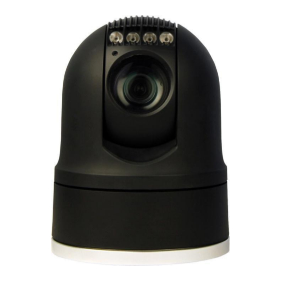
- Page 1 HDC-SDOMEO51MIR-B USER MANUAL HD Portable Rugged PTZ Cameras...
- Page 2 Safety Notes Thank You for Choosing Our HD table Rugged PTZ Camera! When you open the box: 1. Check that the packing and the contents are not visibly damaged. Contact the retailer immediately if any parts are either missing or damaged. 2.
-
Page 3: Table Of Contents
Table of Contents Safety Notes --- Important!!! ................1 About The Product ..................2 Features ......................2 Functions ......................3 Technical Data ....................5 Preparation....................... 7 Dip Switch ....................... 7 Initial Power On Test ..................9 Installation Place .................... 9 Installation .................... -
Page 5: Safety Notes
Safety Notes --- Important!!! The following important notes must be followed carefully to run the camera and respective accessories in total safety. The camera and relative accessories are called video system in this section. Before installing the camera, please read this manual carefully; when installing, please follow instructions of installation indicated in this manual. -
Page 6: About The Product
About The Product The portable rugged PTZ camera is designed for practical and extreme applications, such as military field surveillance, security outdoor evidencing etc. It is featured as weather-proof, anti-vibration and anti-corrosion. It can be deployed into a mobile surveillance system, consisting of ptz camera, vehicle video recorder, monitor, control system and 3G wireless video transmitter. -
Page 7: Functions
About The Product Functions Soft Address The camera address can be programmed with a preset command, and the user does not need to dismount the camera from field or do any screw work. Self-Adaption of Protocol and Baud Rate The camera can automatically identify the protocol (Pelco D/P) and baud rate of the controller and adapt the camera setting accordingly, with no manual DIP Switch involved. -
Page 8: Iris Control
About The Product Target is not in the center of image. Targets are in near and far at the same time. Target is of strong light object. Such as spotlight etc. Target is behind the glass with water drop or dust. ... -
Page 9: Technical Data
About The Product Frame Scan: Make the camera scan between two set positions. [Note] For Frame Scan: The zoom at two limits shall be programed the same. Image Flip Enable you to view image easily when PTZ is either installed on roof of a car or is mounted on the ceiling. - Page 10 About The Product Preset Precision ±0.05° Light (for IR Version) IR Wave Length 850nm 940nm IR Range IR Switch Auto/Manual Light (for White Light Version) Color Temperature 6500K Range Switch Manual General Comm. Interface RS-485 Protocol PELCO-P / PELCO-D, VISCA Baud Rate 2400bps, 4800bps, 9600bps, 19200bps (self-adaptive) Address...
-
Page 11: Preparation
Preparation This section contains detailed instructions for installing the camera. These instructions assume that the installer has a good knowledge of installation techniques and is capable of adopting safe installation methods. Dip Switch The factory default is: Camera Address Protocol Baud Rate Pelco D 9600bps... - Page 12 Preparation SW Position Camera Address SW Position PELCO_D PELCO_P Protocol VISCA Reserved SW Position 2400bps 4800bps Baud Rate 9600bps 19200bps [Note] The camera shall be rebooted after the switches are programmed. [Note] When protocol is programmed as Pelco_D or Pelco_P, the baud rate can be self-adaptive.
-
Page 13: Initial Power On Test
Preparation Initial Power On Test To ensure the camera works well after installation, please power on it for an initial test with the following steps: 1. Connect the camera with correct power supply; 2. Connect control cable, video cable; 3. Power on the camera; The camera will run a calibration procedure on power up and show the following messages on screen. -
Page 14: Installation
Installation There are two types of mounts: the fixed mount and magnetic mount. Fig.3: Fixed Mounts (with damping system) Fig.4: Fixed Mounts (with no damping system) -
Page 15: Magnetic Mount
Installation Magnetic Mount Fig.5: Magnet Mounts (with no damping system) Installation To set the camera hard address: 1. Remove the DIP Switch cover at the bottom; 2. Set DIP Switch for camera address; 3. Fix the cover. Make sure the cover is well sealed with the gasket. Fig.6: Bottom Plate... - Page 16 Installation Fixed Mounts: With Damper 1. Take the damper out of packing and fix it to the target place as per the installation dimensions with correct screws. Fig.7: Installation Plate 2. Put the camera onto the damper. Make sure three installation bolts are in position with the fixing holes on the plate.
- Page 17 Installation 3. Fix the camera to the damper with a screw. Fig.9: Fix the Camera With No Damper 1. Take the PTZ camera out of packing and fix it to the target place as per the installation dimensions with correct screws. Magnetic Mounts: 1.
-
Page 18: Camera Cable Package
Installation Fig.10: Fix the Camera [Note] Please place the ptz camera in a safe place when there is no guard. Camera Cable Package Connect the cable with the right pins as per following pictures. Fig.11: Cable Package... - Page 19 Installation Pin Definition Pin # Definition Video + Power - Power + RS485 - RS485 + Video - [Note] Please make sure the camera is working with a right power supply. Wrong cable connection may cause damage to the device.
-
Page 20: Operation
Operation Special Control Panel Commands The camera can be programmed and operated using various quick control panel commands. Preset Number Function Default Value <20, >82 General preset positions Manual switch between color mode and mono mode Auto switch between color mode and mono mode (for √... -
Page 21: Operation
Operation “-” indicates current function not set or not open;“ √” indicates the default setting of current function;“on”indicates the default mode of current function is on;“off”indicates the default mode of current function is off; Operation As the baud rate and protocol are self-adaptive, the PTZ cameras may not response for seconds on power up. - Page 22 Operation Fig.12: Image Freeze Soft Address The camera address can be changed via presets 62 and 63. The new address will take effect after the camera is rebooted. Digital Image Stabilization (DIS) The function is off as default. It can be turned on/off by calling preset 29. It is used when the camera is used in a vibration environment, to compensate the vibration in video.
- Page 23 Operation Problems Possible Causes Solutions Power supply failure Replace power supply No action when powered Wrong connection Check & reconnect the cables power Mechanical failure Repair Abnormal self-test with Camera inclined Reinstall the camera motor noise Inadequate power supply Replace the power supply Video signal failure Reinstall camera Normal self-test but no...