Table of Contents
Advertisement
Quick Links
Advertisement
Table of Contents

Related Manuals for XtendLan SDOMEOATM


Summary of Contents for XtendLan SDOMEOATM
-
Page 1: User Manual
SDOMEOATM USER MANUAL Object Tracking/High Speed Mini Dome II... - Page 2 Thank You for Choosing our PTZ Camera! When you open the box: Check that the packing and the contents are not visibly damaged. Contact the retailer immediately if any parts are either missing or damaged. Make sure if the contents are all included as per the packing list. ...
-
Page 3: Table Of Contents
Table of Contents Safety Notes --- Important!!! ................1 About The Product ..................... 3 2.1. Features ......................3 2.2. Functions ....................... 3 2.3. Technical Parameters ..................6 Installation......................8 3.1. DIP Switch Setting ..................8 3.2. Installation ..................... 9 Operation Guide ..................... 11 4.1. - Page 4 4.5.4. Alarm ....................44 4.5.5. Track ....................46 4.5.6. Event ....................50 4.5.7. Set Default ..................54 4.6. Special Control Panel Commands ............. 54 Trouble Shooting .................... 56 iii / iii...
-
Page 5: Safety Notes
SAFETY NOTES --- IMPORTANT!!! The following important notes must be followed carefully to run the PTZ camera and respective accessories in total safety. The camera and relative accessories are called video system in this section. Use the instructions correctly and fully Read all safety rules and instructions carefully before starting to run the video system. - Page 6 video system in the event of lightening or electrical line overload. Do not overload the electrical power and the extensions to prevent the risk of fire or electrocution. Do not place the camera near or over radiators or sources of heat. Check that the area is suitably ventilated before installing the camera inside partially closed areas (such as recesses, bookshelves and shelves).
-
Page 7: About The Product
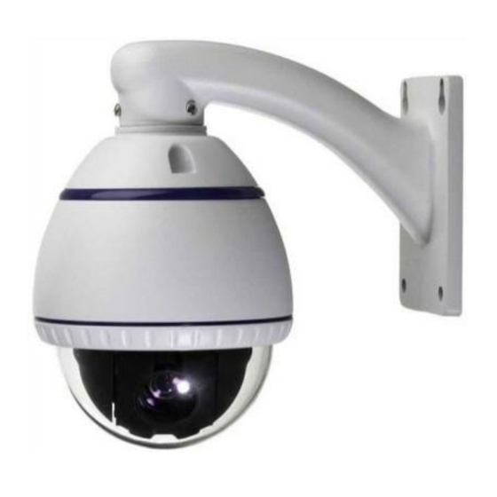
ABOUT THE PRODUCT The Auto Tracking/ High Speed Mini PTZ II is based on our unique motion tracking technology with high resolution, high speed, low price and selectable communication protocols. It is widely used in surveillance system as unattended CCTV device. 2.1. - Page 8 camera can track moving objects automatically. Soft Address The camera address can be programmed with built-in OSD menu, and the user does not need to dismount the camera from field or do any screw work. Wide Dynamic Range (WDR) A camera is intended to provide clear images even under back light circumstances where intensity of illumination can vary excessively, when there are both vary bright and vary dark areas simultaneously in the field of view.
- Page 9 the focus to get the best image. Focus can also be controlled manually from the controller if required. Press Focus Near or Focus Far key to manually focus. Focus can be manual via keyboard or matrix, please refer to control keyboard or matrix operation manual for detailed operation. When adjusting position is set with auto focus status, it goes back to auto focus.
-
Page 10: Technical Parameters
Auto, Random and Frame Scan Auto Scan: Make the camera scan 360º ranging from the current position. Random Scan: Make the camera random scan 360º ranging from the current position. Frame Scan: This feature freezes the scene on the monitor when going to a preset. This allows for smooth transition from one preset scene to another. - Page 11 Sensitivity 0.7Lux(Color) / 0.02Lux(B/W), 50IRE Switch Mode Auto / Day/Night(ICR) Focus Auto / Manual /Semi Auto Iris Auto / Manual Shutter Speed X128~1/120000sec Normal / High / Off White Balance Auto / MAN Low / Mid/ High / Off SSNR Low / Mid/ High / Off Pan:360°continuous, Tilt: 0°~90°...
-
Page 12: Installation
INSTALLATION This section contains detailed instructions for installing the camera. These instructions assume that the installer has a good knowledge of installation techniques and is capable of adopting safe installation methods. 3.1. DIP SWITCH SETTING Before installing the camera drive, check the DIP switch; configure the receiver address, communication protocol, and baud rate setting. -
Page 13: Installation
… … … … … … … … … BAUD (SW2) RATE 1200 BAUD 2400 RATE 4800 (BPS) 9600 PROTOCOL (SW2) PELCO (PELCO-P/ PELCO-D) COMM reserved PTOL reserved reserved Table 2: SWITCH SETTING 3.2. INSTALLATION Step 1. Install lower dome. 9 / 56... - Page 14 Line up the mounting screw holes, and install the three mounting screws. Push the lower dome inside the back box. Step 2. Install the bracket for wall-mounted dome Dig four holes on the wall as Pic. 3. Take out the cables from the backward of the bracket.
-
Page 15: Operation Guide
OPERATION GUIDE 4.1. OPERATION AT POWER UP The camera employs the default settings the first time it is switched on. Changes to the settings will be permanently stored and will be made available the next time the camera is switched on. You can return to the default settings by means of the appropriate menu option at any time. -
Page 16: Control Keypad Password And Access
4.2.1. CONTROL KEYPAD PASSWORD AND ACCESS The system will wait for the password to be entered after being switched on. The control panel requires a 6-digit password. The entered digits will be replaced by a “*” symbol on the screen for privacy. Access to the menu is gained after entering all the digits correctly. -
Page 17: Control Keypad Command Types
CAM + 1 + ENTER 4.2.3. CONTROL KEYPAD COMMAND TYPES There are four command types: Select camera, Move camera (tilt and pan, zoom, adjust focus and IRIS opening, go to preset positions), Adjust camera operation mode using menus, ... - Page 18 The maximum pan span is from 0º to 360º with continuous rotation. The maximum tilt span is from 0º (camera in vertical position) and 90º. The panning and tilting speed can be modulated by operating the joystick appropriately. Note that the maximum speed that can be obtained by operating the joystick is not always equal to that programmed in the working settings.
-
Page 19: Zoom Functions
4.4.2. ZOOM FUNCTIONS The camera frame may be adjusted by using the ZOOM IN and ZOOM OUT commands. Use ZOOM IN to zoom into the detail; use ZOOM OUT to zoom out. Zoom can be set as per the zoom specifications of relative modules, combined between optical zoom and digital zoom. -
Page 20: Function Program Menu
The camera can store up to 256 panning, tilting and zooming configurations (called preset positions) which can be recalled at any time. The manual focusing and IRIS opening settings cannot be stored. When storing presets, it is important to remember that some are reserved and cannot be either stored or used for positioning the camera. - Page 21 MAIN MENU ---------------------------- 1. <SYSTEM> 2. <CAMERA> 3. <PTZ> 4. <ALARM> 5. <TRACK> 6. <EVENT> 7. <SET DEFAULT> 8. SYSTEM REBOOT 9. BACK 10.EXIT Screen 1: Main Menu If a password is required, the following prompt will appear. The password is a numeric combination (max.
-
Page 22: System Menu
Simply press BACK and use OPEN or just press CLOSE to go back to the previous level menu. Option Value Explanation SYSTEM System setting menu (See Section 4.5.1) CAMERA Lens parameters setting menu (See Section 4.5.2) PTZ Setting Menu (See Section 4.5.3) ALARM Alarm setting menu (See Section 4.5.4) TRACK... - Page 23 Program protocol, address, baud rate via OSD SOFT DIP SWITCH menu. DOME LABEL Dome label setting submenu Display submenu: program the info to be DISPLAY SETUP displayed on screen. PASSWORD Password submenu BOOTUP SCREEN Boot up screen submenu Remember the camera position of last power POSITION MEMORY ON/OFF off.
- Page 24 DOME LABEL ---------------------------- 1. <EDIT DOME LABEL> 2. <CLEAR DOME LABEL> 3. BACK 4. EXIT Screen 5: Dome Label Menu Option Value Explanation This submenu is used to edit a dome EDIT DOME LABEL label (see below). This submenu is to clear the label of the CLEAR DOME LABEL camera.
- Page 25 The DISPLAY SETUP submenu is used to enable the labels to be displayed for the various camera functions. DISPLAY SETUP --------------------------- 1. <CLOCK> 2. <ORIENTATION> 3. DOME LABEL: 4. ZOOM: 5. AZIMUTH/ELEVATION: 6. PRESET LABEL: 7. ZONE LABEL: 8. EVENT LABEL: 9.
- Page 26 CLOCK --------------------------- 1. CLOCK DISPLAY: ON 2. DATE: 2010/11/30 3. TIME: 13:12:09 4. BACK 5. EXIT Screen 8: Clock Option Value Explanation CLOCK DISPLAY ON/OFF Show or hide the date and time DATE Set the date. The format is YYYY/MM/DD. time.
-
Page 27: Password
ZONE CAMERA PRESET ORIENT EVENT SAVE RESET AZIMUTH ZOOM TIME DATE Screen 10: Label Position To establish a position: Point the cursor to the label to be moved by moving the joystick vertically. Press OPEN. Symbol “■” will appear. Position the entire label in the chosen position using the joystick. Press OPEN. -
Page 28: Bootup Screen
INPUT OLD PASSWORD PASSWORD 1234567890 CLEAR ENTER BACK Screen 12: Edit Password Select the password digits by moving the joystick horizontally. Symbol “▲” indicates the digit to be entered. Press OPEN to enter the selected digit. The entered numbers will be replaced by a “*” symbol on the screen for privacy. Enter all the digits correctly and select ENTER to confirm. -
Page 29: Exposure
CAMERA --------------------------- 1. DIGITAL ZOOM: 2. BACKLIGHT COMP: 3. <EXPOSURE> 4. <WHITE BALANCE> 5. <DAY/NIGHT> 6. <FOCUS/ IRIS> 7. <PRIVACY> 8. <ADDITIONAL> 9. BACK 10. EXIT Screen 14: Camera Option Value Explanation DIGITAL ZOOM ON/OFF Switch digital zoom ON or OFF. Switch back light compensation ON and OFF. - Page 30 EXPOSURE ------------------------------- 1. AE MODE: 2. LOW LIGHT MODE: 3. LOW LIGHT LIMIT: 4. IRIS LEVEL: 5. AGC LEVEL: 6. SHUTTER SPEED: 1/50 7. SPOT AE: 8. SENSE UP: 9. BACK 10. EXIT Screen 15: Exposure Option Value Explanation AE MODE Not available.
- Page 31 Screen 16: white balance Option Value Explanation White Balance (WB) is performed in auto tracking mode (Auto Tracking White). This mode automatically balances the white level by analyzing a wide range of colors, i.e. all those with temperatures comprised in the range between 2000K and 10000K.
- Page 32 AUTO, Set the D/N level and dwell time by user DAY/NIGHT COLOR, BW, environment. This mode automatically adjusts the D/N LEVEL DWELL TIME This is not supported by Samsung module. Table 14 4.5.2.4. FOCUS/IRIS The FOCUS/IRIS menu is used to set the parameters of focus and iris. FOCUS/IRIS --------------------------- 1.
-
Page 33: Privacy
PEAK Table 15 4.5.2.5. PRIVACY The PRIVACY submenu is used to set the parameters of windows blanking. Some zoom modules may not support this function. Please refer to the data sheet of the module. PRIVACY --------------------------- 1. PRIVACY: 2. DISPLAY: 3. - Page 34 EDIT WINDOWS LOCATION ------------------------------ IRIS OPEN TO CONTINUE IRIS CLOSE TO CANCEL Screen 20: Edit Windows Location Sub-Menu A cross-shaped pointer will appear on the monitor: this pointer will correspond to the middle of the privacy zones being created. Point the cross-shaped cursor to the required position by moving the joystick in the vertical and horizontal directions.
-
Page 35: Additional
It is preferable to set the privacy zones with a zoom level of 1x. 4.5.2.6. ADDITIONAL The additional submenu is used to program other parameters of the zoom module. ADDITIONAL ---------------------------- 1. SHARPNESS: 2. SHARPNESS LEVEL: 3. DNR: MIDDLE 4. -
Page 36: Motion
------------------------- 1. <MOTION> 2. <PRESETS> 3. <SCAN> 4. <POWER UP> 5. <CRUISE> 6. <CLEAR SET> 7. PRESETS NUMBER: 256 8. BACK 9. EXIT Screen 22: PTZ Menu Option Value Explanation MOTION Camera motion parameter programming submenu PRESETS Preset parameter submenu SCAN Pattern and zone parameter submenu POWER UP... - Page 37 MOTION ---------------------------- 1. AUTO FLIP: 2. PROPORTIONAL PAN: 3. PARK TIME: 4. PARK ACT: NONE 5. <SPEED SETTING> 6. <MANUAL LIMIT> 7. <ZONES> 8. BACK 9. EXIT Screen 23: Motion Option Value Explanation When this option movements of a subject moving underneath camera followed...
- Page 38 The camera performs a random scan at the end of the park time: the RANDOM SCAN camera performs a random 360 degree scan pausing approximately 2” every 142°. The camera performs a frame scan at the end of the park time: the FRAME SCAN horizontal scan is performed in the SET SCAN...
- Page 39 Table 19 SPEED SETTING submenu Use the joystick to point the cursor to” SPEED SETTING” option. Press OPEN. The following menu will appear on the display: SPEED SETTING -------------------------------- 1. PAN SPEED<DEG/S>: 150 2. TILT SPEED<DEG/S>: 150 3. BACK 4. EXIT Screen 24: SPEED SETTING Sub-Menu Option Value...
- Page 40 If the option is ON, horizontal automatically LIMIT STOPS ON/OFF scanning is performed within the right and left scanning limits open. Table 21 SET MANUAL STOPS SUBMENU Use the joystick to point the cursor to the “SET MANUAL STOPS” option. Press OPEN.
- Page 41 Option Value Explanation ZONE NUMBER 1 ~ 8 This option is used to select a zone. This submenu is used to associate a label to a EDIT ZONE LABEL zone (see below). This submenu is used to create a zone (see EDIT ZONE below).
- Page 42 Press CLOSE to cancel the operation. 4.5.3.2. PRESETS PRESETS ------------------------------ 1. PRESET NUMBER: **PRESET NOT DEFINED** 2. <EDIT PRESET LABEL> 3. <EDIT PRESET POSITION> 4. <CLEAR PRESET> 5. BACK 6. EXIT Screen 30: Presets Option Value Explanation This option is used to select a presetting for PRESET NUMBER 1-64 entering a descriptive label.
- Page 43 PRESET NUMBER PRESET LABEL 1------- 0123456789 YZ yz ABCDEFGHIJKLMNOPQRSTUVWX abcdefghijklmnopqrstuvwx CN SP BP Screen 31: Preset Label Sub-Menu Point the cursor to the first character to the use and press OPEN. Point the cursor to “BACKSPACE” to delete it. After writing the text, point the cursor to OK and press OPEN to save and go back to the main screen.
- Page 44 Option Value Explanation ZONE SCAN Zone parameter submenu PATTERN SCAN Pattern parameter submenu Table 24 Zone Scan Submenu ZONE SCAN -------------------------------- 1. SCAN SPEED<DEG/S>: 2. <SET ZONE SCAN> 3. BACK 4. EXIT Screen 34: Zone Scan Sub-Menu Option Value Explanation SCAN SPEED 1 ~ 32 This option is used to set scan speed.
- Page 45 SET SCAN STOPS LEFT LIMIT POSITION IRIS OPEN TO CONTINUE IRIS CLOSE TO CANCEL SCREEN 36: SET ZONE SCAN Use the joystick to position left limit and press OPEN to save. SET SCAN STOPS RIGHT LIMIT POSITION IRIS OPEN TO CONTINUE IRIS CLOSE TO CANCEL SCREEN 37: SET ZONE SCAN Use the joystick to position right limit and press OPEN to save.
- Page 46 PROGRAM PATTERN submenu This includes all the operations needed to program a pattern. Use the joystick to point the cursor to the "PATTERN NUMBER” option. Select the required pattern and press OPEN. Position the cursor under “PROGRAM PATTERN” option and press the OPEN button. The number of actions available (including zoom operations) for programming the Pattern is shown in percentage form on the screen while they are each being programmed.
- Page 47 The camera performs tracking action at the TRACKING end of power up. This is only available for the tracking ptzs. Table 27 4.5.3.5. CRUISE SETTING CRUISE ----------------------------- 1. DWELL TIME<SECS>: 2. CRUISE TRACKING: OFF 3. PRESET LIST: 1 ON 0 OFF 1234567890 <PRESET 1-10>...
-
Page 48: Alarm
4.5.3.6. CLEAR SET CLEAR SET ----------------------------- 1. <CLEAR ZONES> 2. <CLEAR PRESETS> 3. <CLEAR PATTERNS> 4. <LOAD DEFAULTS> 5. BACK 6. EXIT Screen 41: Clear Set Submenu This menu is used to delete the settings of several elements at one time. Option Value Explanation... - Page 49 Screen 42: Alarm The camera has 4 alarm inputs and 2 alarm outputs. The actions defined by the user may be associated to an alarm. The camera has 2 alarm outputs (AUX1& AUX2) which may be programmed to activate the external devices in the case of alarm. The 2outputs closed to ground. Option Value Explanation...
-
Page 50: Track
alarm: e.g. a siren. Alarm output polarity: normally open (ON) or normally closed (OFF). ALARM CONTACT ON/OFF The circuit will open to generate an alarm if it is “NC” and will close if it is “NO”. ALARM SETTINGS This submenu contains the alarm settings. This submenu is used to delete the alarm CLEAR SETTINGS programming. - Page 51 Screen 43: Tracking Setting Sub-Menu The auto tracking function is used to automatically track moving objects by detecting grayscale variations in the frame. Option Value Explanation DEFAULT This function is used to load the auto SETTING tracking default settings. This option defines the total dimensions of the object to be tracked.
- Page 52 This option determines the time which must elapse before performing an action after losing a motion in frame. The action (LOST ACT) may consist in: The camera goes back to preset number 1 and tracking is enabled from this 5, 10, 15, 20, position.
- Page 53 TRACKING BOUNDARY --------------------------- 1. BOUNDARY LIMIT: 2. <CLEAR BOUNDARY> 3. LEFT LIMIT: 4. RIGHT LIMIT: 5. UP LIMIT: 6. DOWN LIMIT: 7. BACK 8. EXIT Screen 44: Tracking Boundary Sub-Menu Option Value Explanation This switches tracking function intervention BOUNDARY LIMIT ON/OFF zone on and off.
-
Page 54: Event
TRACKING BOUNDARY option). Avoid background objects in the frame which could trick the motion detector, such as blinds, gates, doors with grid and objects with very marked, contrasting contours. A chequer board background is certainly the worst condition for satisfactory operation. - Page 55 EVENT ------------------------- 1. EVENT NUMBER: 2. <EDIT EVENT LABEL> 3. <EDIT EVENT> 4. <CLEAR EVENT> 5. <LIST EVENT> 6. HOLIDAY: 7. <EDIT HOLIADY> 8. <CLEAR HOLIDAY> 9. <LIST HOLIDAY> 10. BACK 11. EXIT Screen 45: Event menu Option Value Explanation This option is used to select a presetting for entering a descriptive label.
- Page 56 HOLIDAY selected holiday. Press the OPEN button to clear the selected holiday, press CLOSE to cancel. The holiday list submenu. LIST Press OPEN to show all the number and date of the HOLIDAY holidays established. Table 33 EDIT EVENT submenu This includes the operations needed for programming an event.
- Page 57 Set of events and non-implementation of the implementation parameters on and off, set to open when the implementation of the EVENT ACTIVE ON/OFF stipulated time period selected events, set to off when the selected event does not perform. START TIME Set the start time of the selected events.
-
Page 58: Set Default
EDIT HOLIDAY --------------------------- 1. HOLIDAY NUMBER: 2. MONTH: 3. DAY: 4. SAVE 5. CANCEL 6. EXIT Screen 48: Edit Holiday Sub-Menu Option Value Explanation HOLIDAY NUMBER 1~14 Select number of the holiday. MONTH JAN~DEC Select the month of the selected holiday. 1~31 Select the date of the selected holiday. - Page 59 CALL ENTER Stops the tracking function CALL ENTER Starts the cruise function CALL ENTER Delete all Presets CALL ENTER Start pattern 1 CALL ENTER Start pattern 2 CALL ENTER Start pattern 3 CALL ENTER Start pattern 4 CALL ENTER Start park action function CALL ENTER Stop park action function...
-
Page 60: Trouble Shooting
TROUBLE SHOOTING Problem Possible Reason Solution Wrong wire connections Check and reconnect wires Wrong or bad power source Change power source Power on normally but no video signal Fuse broken. Change fuse Power cable is disconnected Reconnect power wiring Address, protocol, and baud Check Pan/Tilt rate is not correctly set...