Table of Contents
Advertisement
Quick Links
Download this manual
See also:
User Manual
Advertisement
Table of Contents

Related Manuals for XtendLan XL-ICA-106M3


Summary of Contents for XtendLan XL-ICA-106M3
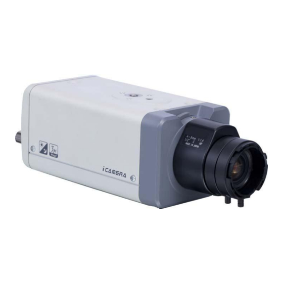
- Page 1 XL-ICA-106M3 Megapixel Indoor Quick Start Guide...
- Page 2 Do not allow the water and other liquid falling into the XL-ICA-106M3. 4. Daily Maintenance Current series XL-ICA-106M3 has no power button. Please unplug all corresponding power cables before your installation. Do not touch the CCD or CMOS part; you can use the blower to clean the dust on the surface of the lens.
- Page 3 C/CS adapter ■ Quick Start ■ Guide ■...
-
Page 4: Table Of Contents
Table of Contents Framework........................... 5 Rear Panel........................5 Side Panel ........................9 Lens ..........................9 Installation ..........................11 Lens Installation......................11 2.1.1 Auto Aperture Lens ..................... 11 2.1.2 Manual Lens......................11 2.1.3 Remove Lens ....................... 12 SD Card ........................12 2.2.1 Installation ......................12 2.2.2 Remove......................... -
Page 5: Framework
1 Framework 1.1 Rear Panel This series IP camera real panel is shown as below. See Figure 1-1. The rear panel with the network port The rear panel with the 100M fiber port Figure 1-1 Please refer to the following sheet for detail information. Interface Name Connector Function... - Page 6 TV monitor to view video. AC 24V/ DC 12V Power port Power port. Input 12V DC or AC 24V STATUS Red light System boot up- Indication Light red light is on Safe mode-red light flashes System upgrades-red light flashes System resets- red light flashes.
- Page 7 function right now. WIFI 3G/WIFI port Connect to 3G/WIFI antenna to receive the wireless signal. Please note this function is for some series products only. Alarm input port I/O port Alarm input port 1. To receive the signal from the external alarm device.
- Page 8 (power indication light is red), press the RESET button for at least 5 seconds, system can restore factory default setup. AUDIO OUT Audio output port Audio output 3.5mm Output audio signal to JACK port. the device such as sound box. AUDIO IN Audio input port Audio input 3.5mm...
-
Page 9: Side Panel
card is not in write mode. Otherwise it may result in data loss or card damage. Before hot swap, please stop record operation. Please make sure the device is securely earthed to prevent the thunderstorm strike. 1.2 Side Panel Please refer to the following interface for side panel dimension information. The unit is mm. See Figure 1-2. - Page 10 Figure 1-3...
-
Page 11: Installation
2 Installation 2.1 Lens Installation 2.1.1 Auto Aperture Lens Please follow the steps listed below for auto aperture lens installation. The interface is shown as in Figure 2-1 and Figure 2-2. Remove the CCD protection cap of the device, and then line up the lens to the proper installation position. -
Page 12: Remove Lens
Figure 2-2 2.1.3 Remove Lens Please follow the steps listed below to remove lens. The interface is shown as in Figure 2-3. Turn the lens counter clockwise and then remove it from the camera. Unplug the auto lens cable socket from the auto lens connector. If you are using the manual aperture lens, please skip to the following step. -
Page 13: Remove
Figure 2-4 Figure 2-5 2.2.2 Remove Please follow the steps listed below to remove SD card. The interface is shown as Figure 2-6. Use the screwdriver to loosen the screw of SD card protection cap in the rear panel. Remove the cap from the camera. Follow the SD card direction to remove the SD card. -
Page 14: Card
2.3 3G Card 2.3.1 Installation The 3G card installation is the same with the SD card. Please follow the steps listed below to install 3G card. The interfaces are shown as Figure 2-7 and Figure 2-8. Use the screwdriver to loosen the 3G card protection cap screw in the side panel, and then remove the 3G card protection cap from the camera. -
Page 15: Wifi Antenna
Figure 2-9 2.4 3G/WIFI Antenna 2.4.1 Installation Line up the thread of the screw of the 3G/WIFI antenna to the thread of the rear panel. See Figure 2-10. Please turn according to the direction in the following figure until antenna is secure firmly. See Figure 2-11. -
Page 16: Remove
After you fix the 3G/WIFI antenna to the WIFI port of the rear panel, you can adjust the antenna direction. See Figure 2-12. Figure 2-12 2.4.2 Remove Use your hands to hold the 3G/WIFI thread end and then turn according to the following figure. See Figure 2-13. -
Page 17: I/O Port
Remove the 3G/WIFI antenna from the port of the rear panel. See Figure 2-15. Figure 2-15 2.5 I/O Port Install Cable Please follow the steps listed below to install the cable. See Figure 2-16. Use the small slotted screwdriver to press the corresponding button of cable groove. Insert the cable into the groove and then release the screwdriver. -
Page 18: Quick Configuration Tool
3 Quick Configuration Tool 3.1 Overview Quick configuration tool can search current IP address, modify IP address. At the same time, you can use it to upgrade the device. Please note the tool only applies to the IP addresses in the same segment. 3.2 Operation Double click the “ConfigTools.exe”... - Page 19 Select the “Open Device Web” item; you can go to the corresponding web login interface. See Figure 3-3. Figure 3-3 If you want to modify the device IP address without logging in the device web interface, you can go to the configuration tool main interface to set. In the configuration tool search interface (Figure 3-1), please select a device IP address and then double click it to open the login interface.
- Page 20 Figure 3-5 For detailed information and operation instruction of the quick configuration tool, please refer to the Quick Configuration Tool User’s Manual included in the resources CD.
-
Page 21: Web Operation
Please follow the steps listed below for network connection. Make sure the XL-ICA-106M3 has connected to the network properly. XL-ICA-106M3 IP address and PC IP address shall be in the same network segment. XL-ICA-106M3 default IP address is 192.168.1.108. If there is router, please set the corresponding gateway and subnet mask. - Page 22 Figure 4-2 After installation, the interface is shown as below. See Figure 4-3. Please input your user name and password. Default factory name is admin and password is admin. The login type includes: TCP/UDP/Multicast. Note: For security reasons, please modify your password after you first login. Figure 4-3 After you logged in, you can see the main window.
- Page 23 Figure 4-4 Please refer to the Web Operation Manual included in the resource CD for detailed operation instruction.
-
Page 24: Appendix Toxic Or Hazardous Materials Or Elements
Appendix Toxic or Hazardous Materials or Elements Component Name Toxic or Hazardous Materials or Elements Cr VI PBDE ○ ○ ○ ○ ○ ○ Circuit Board Component ○ ○ ○ ○ ○ ○ Device Construction Material ○ ○ ○ ○ ○...