Table of Contents
Advertisement
Quick Links
Installation
Location
Location
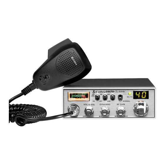
Plan location of transceiver and microphone
bracket before starting the installation.
Select a location that is convenient for operation,
yet does not interfere with the driver or passenger.
The transceiver is usually mounted to the under-
side of the dash with the microphone bracket
beside it.
Mounting and
Mounting and Connection
Connection
Hold the radio with the mounting bracket in
1
the exact desired location. If there is no inter-
ference, remove the bracket and use it as a
Note
template to mark the location for the mount-
The transceiver is held in the
ing screws.
universal mounting bracket by
two thumbscrews which allow
for adjustment at a convenient
angle.
The bracket includes two self-
tapping screws and star wash-
ers. The mounting must be
mechanically strong, conve-
niently located.
Drill the holes and secure the bracket.
2
3
Connect the antenna cable plug to the recep-
tacle marked "ANT" on the back of the unit.
Installation
Note
Before installing the CB radio,
visually check the vehicle's bat-
tery connection to determine
which terminal, positive or
negative, is grounded (positive
is the larger of the two) to the
engine block (or chassis). A
negatively grounded vehicle
has its negative lead grounded
to the chassis.
Note
In positive ground vehicles the
red wire goes to the chassis and
the black wire is connected to
the ignition switch.
Advertisement
Table of Contents

Related Manuals for Cobra 25 LTD


Summary of Contents for Cobra 25 LTD
- Page 1 Installation Installation Location Location Plan location of transceiver and microphone bracket before starting the installation. Select a location that is convenient for operation, yet does not interfere with the driver or passenger. Note The transceiver is usually mounted to the under- Before installing the CB radio, side of the dash with the microphone bracket visually check the vehicle’s bat-...
-
Page 2: Installation
Installation Installation Note Connecting to an accessory fuse prevents the unit from being left Plug power cable into back of unit marked on accidentally, and also per- “Power”. Be sure to observe polarity markings. mits operating the unit without running the engine. Mount the microphone bracket on the right side Note... -
Page 3: Operation
Operation Operation Turning On Setting Channel Turning On Setting Channel Selector Selector Make sure the power cord, antenna and micro- phone are connected to their proper connectors before starting. Select one of forty channels and adjust volume. The selected channel is indicated by the LED readout directly above the channel selector knob CB/PA button should be in the... -
Page 4: Selecting A Channel
Operation Operation To Receive S-Meter S-Meter To Receive Swings proportionately to strength of incoming signal when receiving. Rotate the On/Off Volume knob clockwise the green RT/TX LED and channel display will be illuminated. Selecting A Selecting A Channel Channel Note Switch to 9 (Emergency) for instant access to these channel. -
Page 5: Rf Gain Control
Operation Operation NB, OFF NB, OFF (Noise Blanker) Switch Bright/Dim Switch Bright/Dim (Noise Blanker) Switch Switch Note When switched to NB position the RF Noise Switch to BRT or DIM to control brightness The RF noise blanker is very Blanker is activated, providing increased noise of the channel indicator and multi-function effective in reducing repetitive filtration. -
Page 6: Setting Squelch
Operation Operation Setting Squelch Setting Squelch Gate set to Desired Squelch Setting (DSS) Squelch is the “control gate” for incoming signals. Gate closed STRONG SIGNALS STRONG SIGNALS MEDIUM SIGNALS MEDIUM SIGNALS WEAK SIGNALS To achieve the Desired Squelch Setting (DSS), WEAK SIGNALS turn the Squelch control counterclockwise... - Page 7 Operation Operation To Transmit Transmit Transmit To Transmit PUSH & Caution! HOLD Be sure the antenna is properly connected to the radio before transmitting. Prolonged trans- mitting without an antenna, or a poorly matched antenna, could cause damage to the transmitter.
-
Page 8: External Speaker
Note The speaker should be directed Connect an external PA speaker to the PA jack away from the microphone to Cobra external speakers are on the rear panel. prevent acoustic feedback. rated at 10 watts. Connect an external speaker to the external speaker jack on the rear panel. -
Page 9: Temporary Mobile Set-Up
Mobile Set-Up For temporary mobile operation you may want to purchase an optional cigar lighter adapter from your COBRA dealer. This adapter and a magnetic mount antenna allow you to quickly “install” your transceiver for temporary use. Adjust PA speaker volume with the... -
Page 10: Home And Office Set-Up
Home And Office Set-Up Home And Office Set-Up Base Station Base Station Operation (From 120V AC House Current) Operation (From 120V AC To operate your transceiver from home or office House Current) you will need a 13.8 volt DC Power Pack rated at a minimum of 2 amps, and a properly installed base station antenna. -
Page 11: How Your Cb Can Serve You
Identify yourself. Evanston. ” L ocation Be exact. I njuries Number. Type. Trapped? “Halloween patrol number 3. P roblem Give details and help needed. All quiet. ” Transmit CLIP repeatedly so any monitor can assist. COBRA RADAR DETECTORS GPS RADAR DETECTOR...