Table of Contents
Advertisement
Advertisement
Table of Contents

Related Manuals for Makita SKR300


Summary of Contents for Makita SKR300
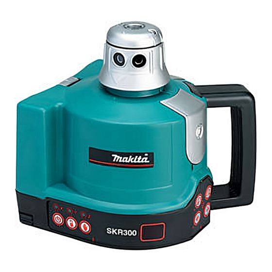
- Page 1 SKR300 Service Manual SKR300 (version 1-12-03)
-
Page 2: Table Of Contents
Table of Contents 1. Introduction a. SKR300 Specifications Page b. LDR180,TL25 Specifications Page c. Overview Page d. Keypad overview Page 2. Operation a. Horizontal setup Page b. Vertical setup Page c. Using the laser chalk line Page d. Using the scanning Page e. -
Page 3: Introduction
1. Introduction The SKR300 is an automatic visible laser that can be used for levelling, vertical alignment, plumbing and squaring. The SKR300 laser has these advanced features: • Automatic self-levelling in both horizontal and vertical modes • Choice of beams: rotation plane, scanning, chalk line, single point or constant squaring •... -
Page 4: Skr300 Specifications
SKR300 Specifications Operational range (diameter) 1,000 ft. (300m) with detector levelling range 5.7° or 10% levelling accuracy horizontal & vertical 30” or 3/16” at 100 ft. or 10mm at 100m (5 mm cone) Chalk line accuracy 10 mm at 30 m... -
Page 5: Ldr180,Tl25 Specifications
Operational Range 30m interior (150 ft.) / 15m exterior Power 1,5v alkaline battery (AA) Battery life 16 hours Weatherproof IP61 Size ” x 2” x 0.8” (85 x 50 x 20 mm) Weight 45 g Page 4 SKR300 (version 1-12-03) -
Page 6: Overview
Arrow (align with 90° index mark) 90° index mark (X1,X2,Y1,Y2) Retractable foot for vertical setup Adjustable feet for vertical setup Batteries (rechargeable or alkaline) Jack for rechargeable battery 5/8 – 11 mount Top cover Vial for vertical rough levelling Page 5 SKR300 (version 1-12-03) -
Page 7: Keypad Overview
Manual mode light / Z Axis calibration indicator Manual / Automatic H. I. Alert light / Y Axis calibration indicator H. I. Alert (Tilt) Battery low light / X Axis calibration indicator On / Off 24. 22. 20. Page 6 SKR300 (version 1-12-03) -
Page 8: Operation
If the laser is disturbed, the head will stop rotating, laser beam shut off and the H.I. light will be solid on. You have to restart the instrument and check the reference. Works with 3 beams mode (Normal, Chalk Line, Scanning). Automatic / Manual Key Page 7 SKR300 (version 1-12-03) - Page 9 Default mode when laser is switched on Man : Manual use. The SKR300 laser is always in the automatic self-levelling mode (auto) when turned on. Once the instrument has self-leveled, the laser head will start rotating. You can choose to have constant rotation by using the Manual mode. This way, the beam will rotate even if the instrument is not leveled.
-
Page 10: Horizontal Setup
2a. Horizontal Setup The SKR300 can be used directly on the ground or mount on a standard tripod (5/8-11). Press the On/Off key to switch the laser on. It will start automatic levelling. To stop the rotation, press once on opposite direction Left (14) or Right (15). -
Page 11: Vertical Setup
You can move the line by rotating the head manually or by using the remote control. Note : The LDR180 detector will not work with the chalk line Page 10 SKR300 (version 1-12-03) -
Page 12: Using The Scanning
(23) blink and then stay on. Recharge battery pack or replace both alkaline batteries at the same time. The SKR300 can be charged while working. If electricity is available on the job site, simply plug in the charger and keep on working. -
Page 13: Self Test Mode
The laser beam should be on and the head will turn and levelling motors will move to end of X,Y axis. The test will not stop until power off. ( Step 7) ( Step 9 ) Page 12 SKR300 (version 1-12-03) -
Page 14: Disassembly
3. Disassembly CAUTION: AVOID staring or looking directly into the laser light. SKR300 is a laser diode, class IIIR product. When adjusting, care must be taken to meet IIIR requirements. Following page is a flow chart showing the order of disassembling the SKR300, but before disassembling, take out the batteries. -
Page 15: Remove Lower Housing, X/Y Motor
Laying the upper housing aside. Be careful not c) Remove X / Y motor to damage all the cables and connectors d) Reverse steps c) – a) to place new motor Page 14 SKR300 (version 1-12-03) -
Page 16: Remove Pcb
Unplug all the connectors by using a tweezers / small flat screw driver to unlock the inter-lock of connectors d) Unlock and unplug keypad flat cable* e) Remove 3 screws (D20) to release PCB * NOTE : Twist the keypad flat cable a bit for easier plug back Page 15 SKR300 (version 1-12-03) -
Page 17: Two Versions Pcb
Rotation motor X motor Z sensor Laser Y sensor Diode X sensor Scanning 3c. Two versions PCB Scanning Y motor Rotation Old version motor Z sensor X motor Laser Battery Y sensor Diode X sensor Page 16 SKR300 (version 1-12-03) -
Page 18: Inner Module
Remove Rotating head assembly c) Un-hook X and Y adjusting spring d) Remove Locating ring by snap ring pliers e) Remove Inner module f) Reverse steps d) to a) to put in new Inner module Page 17 SKR300 (version 1-12-03) -
Page 19: D. Inner Module
3d. Inner module Caution: Calibration required. Please make sure you have proper tools and qualify engineer to perform the calibration. The SKR300 can be out of specification without calibration. Replace Laser diode a) Unlock 3 screws to remove laser diode from Inner... -
Page 20: Rotating Head Disassembly
Hold the side of head mirror (A8) and pull upward to remove head mirror. Be careful not to touch the glass surface. c) Clean and apply small amount of SPG35SL to the o-ring before assemble the rotating head. Page 19 SKR300 (version 1-12-03) -
Page 21: Housing Disassembly
5. Housing disassembly Page 20 SKR300 (version 1-12-03) -
Page 22: Battery Pack Disassembly
6. Battery pack Alkaline Rechargeable Battery Pack Battery Pack Page 21 SKR300 (version 1-12-03) -
Page 23: Ldr180 Remote Disassembly
Remove 3 screws (Item no. 15) to remove PCB f) Clean and apply small amount of SPG35SL on waterproof seal before cover the case back d) Reverse steps e) - a) to put back Page 22 SKR300 (version 1-12-03) -
Page 24: Calibration
11. With X2 facing the marks, bring the laser beam Axis up or down to the center mark by using (2) or (3) (5) Save on the detector or remote. 12. Next, check Y axis. Page 23 SKR300 (version 1-12-03) -
Page 25: Y-Axis Calibration
Press (14) on keypad or (5) on detector or (4) Change remote to save calibration data. If you don’t Axis wish to save the calibration, press the On / Off (5) Save key (24) on the laser. Page 24 SKR300 (version 1-12-03) - Page 26 3. Project the line to a wall 10 meters away. 4. Check if the chalk line is within 5mm margin by rotating the laser head slowly. 5. Adjust the 3 screws to minimize the error. Page 25 SKR300 (version 1-12-03)
-
Page 27: Z-Axis Calibration
The laser is now calibrated in Z axis. Press (14) on laser or (5) on detector or remote to save the calibration data. If you don’t wish to save the calibration, press the On / Off key on the laser. Page 26 SKR300 (version 1-12-03) -
Page 28: Troubleshooting
Motor Failure Battery, X / Y Motor, PCB Excessive Rotation Noise X / Y Motor, Inner Modular Accuracy out of Specification Calibration, Inner Modular Laser frequently re-levelling Check PCB IC vision is SAGA R6 or above Page 27 SKR300 (version 1-12-03) -
Page 29: Laser Light And Motor Failures
9a. Laser Light and Motor Failures Page 28 SKR300 (version 1-12-03) -
Page 30: Laser Light Problem
9b. Laser Light Problem Page 29 SKR300 (version 1-12-03) -
Page 31: Y Motor Failure
X / Y Motor Failure Page 30 SKR300 (version 1-12-03) -
Page 32: Excessive Rotation Noise
Excessive Rotation Noise Page 31 SKR300 (version 1-12-03) -
Page 33: Accuracy Out Of Specification
9e. Accuracy out of Specification Page 32 SKR300 (version 1-12-03) -
Page 34: Spare Parts Lists
10. Spare Parts List Page 33 SKR300 (version 1-12-03) - Page 35 O - ring diameter 41 3,20 0.125.00 O - ring diameter 2.9 1,00 0.126.00 Line generater assembly 6,93 CT.000.05 Makita head body section HV silver 10,50 T.000.00 HV head support with mirrors 42,00 0.129.00 Screw M3 x 3 STHC 2,10 0.130.00 Washer M2.5 (2.7 / 6 / 0.5)
- Page 36 Bearing diameter 17 13,66 0.106.00 Pin diameter 3 x 28 6,30 0.107.0A Silver horizontal support 1,50 0.103.05 Upper body with MAKITA printing 6,00 0.110.00 Adjusting spring for automatic laser X axis 6,70 0.111.00 Adjusting spring for automatic laser Y axis 6,70 0.112.0A...
- Page 37 0.237.10 Automatic axle assembly with sphere 1,78 0.239.00 Plastic ring (sectioned) 1,00 0.241.00 Motorised levelling assembly 22,96 D33S 0.245.15 Keyboard auto SKR300 14,10 0.215.00 Screw 50 x 25 2,50 D36S 0.248.20 Motor brace with notch 1,00 D63S 0.244.11 Automatic PLB assembly HV...
- Page 38 0.163.20 Laser diode 635/2 assembly 57,00 0.122.00 Screw M3 x 8 TCHC Batch : 10 pcs 2,10 0.186.00 O-ring D3.3 x 2.4 – 70sh Batch : 10 pcs 1,00 * Defective item must be returned Page 37 SKR300 (version 1-12-03)
- Page 39 Black battery pack 3,50 E – Rechargeable Battery pack Code Ref. Description Batch Prices 0.142.01 Tubular seal (50 + 20 cm) 1,00 0.302.00 Un-removable screw 4,90 0.303.00 Securing ring 1,00 PA.000.02 Black rechargeable battery assembly 16,00 Page 38 SKR300 (version 1-12-03)
-
Page 40: Remote Control
Lower body section 1,52 CR.019.00 Detector gasket 1,50 CR.020.00 Battery cover 2,29 CR.021.00 M3 screw 1,50 CR.022.00 Plastic window 1,00 CR.023.05 LDR180 receiver rear overlay Makita 2,15 CR.024.00 Buzzer assembly 1,80 CR.025.00 LDR180 Bracket 7,00 Page 39 SKR300 (version 1-12-03) - Page 41 11. Tools Screwdrivers Tweezers Lens tissue Snap ring pliers (10~50mm) IC extractor tool Hexagonal wrench 1.5mm, 2.0mm, 2.5mm Electrolube SPG353L Calibration diode base (reference : 5.011.00 – see page 18) Page 40 SKR300 (version 1-12-03)