Table of Contents
Advertisement
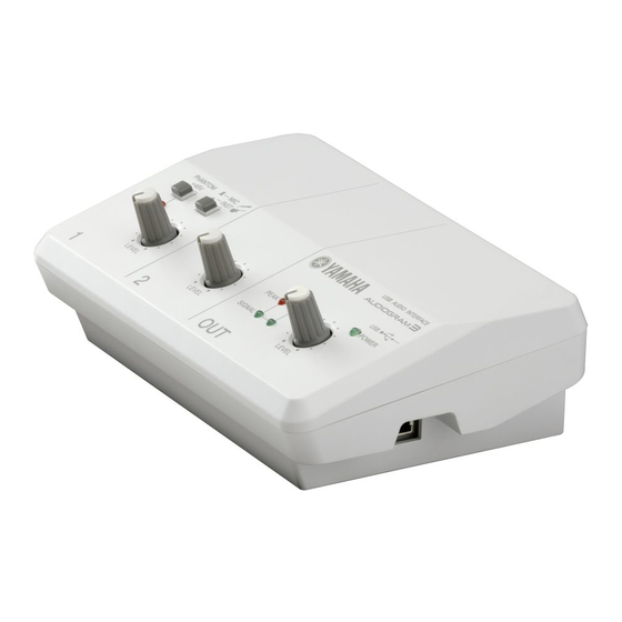
USB AUDIO INTERFACE
SY
011918
20080801 オープンプライス
SERVICE MANUAL
CONTENTS(目次)
SPECIFICATIONS(総合仕様) .................................................3
DIMENSIONAL DIAGRAM(寸法図) ........................................3
PANEL LAYOUT(パネルレイアウト) ......................................4
CIRCUIT BOARD LAYOUT(ユニットレイアウト) .................5
DISASSEMBLY PROCEDURE(分解手順) ..............................6
LSI PIN DESCRIPTION(LSI 端子機能表) ...............................8
IC BLOCK DIAGRAM(IC ブロック図) ....................................9
CIRCUIT BOARDS(シート基板図) .......................................10
INSPECTIONS(検査) .......................................................12/15
(Cubase AI 4 を使用しての録音) ......................................18/23
(TWE を使用しての録音) ..................................................28/31
Copyright (c) Yamaha Corporation. All rights reserved. PDF
HAMAMATSU, JAPAN
'08.07
&
Advertisement
Table of Contents

Related Manuals for Yamaha Audiogram 3


Summary of Contents for Yamaha Audiogram 3
-
Page 1: Table Of Contents
INSPECTIONS(検査) ............12/15 RECORDING USING THE CUBASE AI 4 (Cubase AI 4 を使用しての録音) ........18/23 RECORDING USING THE TWE (TWE を使用しての録音) ..........28/31 PARTS LIST BLOCK DIAGRAM(ブロックダイアグラム) CIRCUIT DIAGRAM(回路図) 011918 HAMAMATSU, JAPAN 20080801 オープンプライス Copyright (c) Yamaha Corporation. All rights reserved. PDF ’08.07 &... - Page 2 IMPORTANT NOTICE This manual has been provided for the use of authorized Yamaha Retailers and their service personnel. It has been assumed that basic service procedures inherent to the industry, and more specifically Yamaha Products, are already known and understood by the users, and have therefore not been restated.
-
Page 3: Specifications(総合仕様
AUDIOGRAM3 SPECIFICATIONS(総合仕様) General Specifi cations Jacks MIC/INST Input Jack x 1 Combo jack (Mic/HiZ) x 1 Phone jacks LINE Input Jacks (L, R) x 1 RCA pin jacks PHONES Jack x 1 Phone jack STEREO OUT Jacks (L, R) x 1 Phone jacks x 1 RCA pin jacks USB Connector x 1 USB 1.1 44.1/48 kHz, 16 bit... -
Page 4: Panel Layout(パネルレイアウト
AUDIOGRAM3 PANEL LAYOUT(パネルレイアウト) • Control Panel • Control panel • コントロールパネル q PHANTOM +48V Switch/Indicator q PHANTOM +48V スイッチ / インジケーター w MIC/INST Switch w MIC/INST 切り替えスイッチ e LEVEL Controls e LEVEL コントロール r POWER Indicator r POWER インジケーター t Level Indicators t レベルインジケーター... -
Page 5: Circuit Board Layout(ユニットレイアウト
AUDIOGRAM3 CIRCUIT BOARD LAYOUT(ユニットレイアウト) MIX3 BOTTOM CASE PRINTED (ボトムケース印刷上り) JACK3 BOTTOM CASE PRINTED (ボトムケース印刷上り) PS-USB ASSEMBLY (PS‒USB Ass’ y) • PS-USB ASSEMBLY PSUSB SHIELD PS-USB (シールドPS‒USB)... -
Page 6: Disassembly Procedure(分解手順
AUDIOGRAM3 DISASSEMBLY PROCEDURE(分解手順) Precautions(注意事項) During assembly, pay attention that connectors, cables or the like are not pinched by circuit boards, frames, etc. ● 組み立てるときは、基板やフレームなどでコード類をはさまないように注意してください。 ● Top Cover Assembly トップカバー Ass'y (所要時間:約 1 分) (Time required: About 1 minute) [140] のネジ 4 本を外して、トップカバー Ass'y を Remove the four (4) screws marked [140]. - Page 7 AUDIOGRAM3 PSUSB Circuit Board PSUSB シート (所要時間:約 6 分) (Time required: About 6 minutes) トップカバー Ass'y を外します。 (1 項参照) Remove the top cover assembly. (See procedure 1.) MIX3 シートを外します。 (2 項参照) Remove the MIX3 circuit board. (See procedure 2.) [80] の ネ ジ 2 本 を 外 し て、JACK3 シ ー ト と PS- Remove the two (2) screws marked [80].
-
Page 8: Lsi Pin Description(Lsi 端子機能表
AUDIOGRAM3 LSI PIN DESCRIPTION(LSI 端子機能表) PCM2904DBR (X9570A00) STEREO AUDIO CODEC WITH USB INTERFACE PSUSB: IC102 NAME FUNCTION NAME FUNCTION USB differential input/output plus DAC analog output for R-channnel USB differential input/output minus DAC analog output for L-channnel Connect to USB power (V Internal analog power supply for PLL CCP1I DGNDU... -
Page 9: Ic Block Diagram(Ic ブロック図
AUDIOGRAM3 IC BLOCK DIAGRAM(IC ブロック図) BA10339F-E2 (X6266A0R) NJM2374AM-TE1 (X9482A00) MIX3: IC402 PSUSB: IC401, IC501, IC601 Ground Sense Comparator PWM DC/DC Converter OUT2 OUT3 Logic 1.5A OUT1 OUT4 160Ω -IN1 +IN4 Vth=300mV Maximum +IN1 -IN4 ON duty 9.1 OSC BLOCK -IN2 +IN3 Ipk Sense -IN3... -
Page 10: Circuit Boards(シート基板図
AUDIOGRAM3 CIRCUIT BOARDS(シート基板図) JACK3 Circuit Board (X9390D0) .............. 11 MIX3 Circuit Board (X9390D0) ..............10 PSUSB Circuit Board (X9388C0) ............. 11 Note: See parts list for details of circuit board component parts. 注 : シートの部品詳細はパーツリストをご参照ください。 MIX3 Circuit Board to JACK3-CN101 to JACK3-CN301 /INST PHANTOM... - Page 11 AUDIOGRAM3 JACK3 Circuit Board LINE STEREO OUT MIC/INST PHONES PHONES to MIX3-CN102 to MIX3-CN302 Component side(部品側) X9390C0 R502 Pattern side(パターン側) PSUSB Circuit Board to MIX3-CN501 Pattern side(パターン側) Component side(部品側) JACK3: 2NA-WM90310-1 PSUSB: 2NA-WW90300-1...
- Page 12 AUDIOGRAM3 INSPECTIONS Measurement condition Environment Temperature (5˚C – 40˚C) Humidity (30% – 90%) Power supply Power is supplied from a personal computer. (Powered through USB bus) Electric characteristics 0 dBu = 0.775 Vrms Preparation Load resistor of each output terminal is as follows: PHONES (L, R) : 40 Ω...
- Page 13 AUDIOGRAM3 Gain Check that the output level of each output terminal is within the range shown in the [Table 2-6.1] and [Table 2-6.2]. * Check that the difference in the level between channels is 2.0 dB or less. Table 2-6.1 INPUT1 [dBu] Input LEVEL STEREO OUT L...
- Page 14 AUDIOGRAM3 2-11 Maximum output Input signal to the INPUT1 and check that the distortion (T.H.D.) is 1.0 % or less when the output signal at the STEREO OUT L, R is +14.0 dBu. Check that the distortion (T.H.D.) is 1.0% or less when the output level at the PHONES L, R is 0.0 dBu. * Set the LEVEL control of the INPUT2 to minimum.
- Page 15 AUDIOGRAM3 検査 測定条件 環境 温度(5℃∼ 40℃) 湿度(30%∼ 90%) 電源 電源はパーソナルコンピュータより供給されます。 (USB バスパワード) 電気的特性 0 dBu = 0.775 Vrms 準備 各出力端子の負荷抵抗は下記の通りです。 PHONES (L, R) : 40 Ω(3 W 以上) Others : 10k Ω 特に指定の無い場合、ツマミ類は以下のように設定してください。 ・ INPUT1 INPUT1 INPUT2 OUTPUT LEVEL control (GAIN control) : 最大...
- Page 16 AUDIOGRAM3 ゲイン 各出力端子に得られる出力レベルは[表 2-6.1] 、 [表 2-6.2]の範囲内であることを確認します。 * チャンネル間レベル差は「2.0 dB」以下であることを確認します。 表 2-6.1 INPUT1 [dBu] Input LEVEL STEREO OUT L STEREO OUT R INPUT level control (PHONE) (PHONE) PHONE -66.0 -2.0 ± 2.0 – 最大 -22.0 最小 -3.0 ± 2.0 -3.0 ± 2.0 -50.0 最大...
- Page 17 AUDIOGRAM3 2-11 最大出力 「INPUT1」に信号を入力し、 「STEREO OUT L, R」に「+14.0 dBu」の出力が得られた時の歪率(T.H.D.)は「1.0%」 以下であることを確認します。 「PHONES L, R」に「0.0 dBu」の出力が得られた時の歪率(T.H.D.)は「1.0%」以下であることを確認します。 *「INPUT2」の「LEVEL コントロール」は「最小」に設定してください。 *「STEREO OUT L, R」測定時は、 「PHONES L, R」の負荷抵抗を接続しないでください。 2-12 入力換算雑音 「XLR 端子」 の 2‒3 ピン間を「150 Ω」で接続した時、 「STEREO OUT L, R」に得られるノイズレベルは「-61.0 dBu」 以下であることを確認します。 ノイズレベルが「-61.0 dBu」以上の場合は、入力換算ノイズレベルが「-125.0 dBu」以下であることを確認します。 *「入力換算ノイズレベル」=「ノイズレベル」−「チャンネルゲイン」...
-
Page 18: Recording Using The Cubase Ai 4
AUDIOGRAM3 RECORDING USING THE CUBASE AI 4 * Insert the attached DVD-ROM (X8515B00) and install the Cubase AI 4. (“Cubase AI 4” is a trademark of Steinberg Media Technologies GmbH.) [Connection] -50.0 dBu +14.0 ± 3 dBu MIC (XLR) STEREO OUT (L/R) USB cable Cubase AI Computer... - Page 19 AUDIOGRAM3 The ASIO Direct Sound Full Duplex Setup dialog box will be displayed. Check only the input port and output port [USB Audio CODEC] checkboxes and click [OK] to close the dialog box. Check that [USB Audio CODEC-1] and [USB Audio CODEC-2] are assigned to the [Port System Name] in the [Ports] fi...
- Page 20 AUDIOGRAM3 Select [New Project] from the [File] menu to create a new project fi le. Move the cursor to a place around the arrow in the fi gure above, click the right mouse button and select “Add Audio Track”. “Add Audio Track”...
- Page 21 AUDIOGRAM3 Click the RECORDING button to start recording. When the recording is to be stopped, click the STOP button Click the PLAY button to play back. Check that the output is +14.0 ± 3.0 dBu. * If the cursor is not at the top, click to put the cursor to the top before starting playback.
- Page 22 AUDIOGRAM3 ● If the “State” is not “Active”. If the State is not Active, check the VST connection. 1. Select [Device] → [VST connection]. 2. “Not connected” is assigned to “Audio Device” fi eld. Change to ASIO DirectX Full Duplex Driver.
-
Page 23: Cubase Ai 4 を使用しての録音
AUDIOGRAM3 Cubase AI 4 を使用しての録音 ※ 付属の DVD-ROM(X8515B00)を挿入し、Cubase AI 4 をインストールしてください。 (Cubase AI 4 は Steinberg Media Technologies GmbH 社の商標です。 ) [接続] -50.0 dBu +14.0 ± 3 dBu MIC (XLR) STEREO OUT (L/R) USBケーブル Cubase AI コンピューター 最大 最大 Cubase AI 4 を起動します。... - Page 24 AUDIOGRAM3 ASIO Direct Sound Full Duplex Setup ダイアログが表示されます。出力ポートと入力ポートの設定 で [USB Audio CODEC] のみにチェックを入れ、[OK] をクリックしてダイアログを閉じます。 デバイス設定ウィンドウの [ ポート ] 欄の [ ポートシステム名称 ] が [USB Audio CODEC-1]、[USB Audio CODEC-2] になっていることを確認し、[ 表示 ] 欄にチェックを入れます。[OK] をクリック してデバイス設定ウィンドウを閉じます。 (チェックが入っていればそのまま [OK] をクリックしてください。 ) ※ 設定がアクティブになっていない場合は、27 ページを参照してください。 ·...
- Page 25 AUDIOGRAM3 [ ファイル ] メニュー→ [ 新規プロジェクト ] を選択し、新規プロジェクトファイルを作成します。 上図矢印のあたりにカーソルを置いてマウスを右クリックし、[ オーディオトラックを追加 ] を選択するとオーディ オトラックを追加ダイアログが表示されます。 下図の設定になっていれば [OK] をクリックします。...
- Page 26 AUDIOGRAM3 録音ボタン をクリックして録音を開始します。適当な位置で STOP ボタン をクリック し録音を終了します。 再生ボタン をクリックして再生します。 出力が +14.0 ± 3.0 dBu となることを確認します。 ※ カーソルが戻っていない場合は をクリックしてカーソルを開始位置に戻してから再生してください。 カーソル...
- Page 27 AUDIOGRAM3 ● 設定状況がアクティブになっていない場合 設定状況がアクティブになっていない場合は、VST コネクションの確認を行なってください。 1. [ デバイス ] → [VST コネクション ] を選択します。 2. [ オーディオデバイス ] 欄が未接続となっていますので、ASIO DirectX Full Duplex Driver に変更します。...
-
Page 28: Recording Using The Twe
AUDIOGRAM3 RECORDING USING THE TWE * Download the TWE from the Yamaha Offi cial site. [Connection] -50.0 dBu +14.0 ± 3 dBu MIC (XLR) STEREO OUT (L/R) USB cable Cubase AI Computer Maximum Maximum Launch TWE. Select [Windows Sound Device Confi guration] from the [Options] menu to open the Windows Sound Device Confi... - Page 29 AUDIOGRAM3 Select [New] from the [File] menu to open the New window. Click [New] in the lower right portion of the New window to open a new fi le (TWE_NEW_XX-XX-XX.WAV).
- Page 30 AUDIOGRAM3 Click the RECORDING button to start recording. When the recording is to be stopped, click the STOP button Click the PLAY button to play back. Check that the output is +14.0 ± 3.0 dBu. * If the cursor is not at the top, click to put the cursor to the top before starting playback.
-
Page 31: Twe を使用しての録音
AUDIOGRAM3 TWE を使用しての録音 ※ TWE はヤマハホームページからダウンロードしてください。 [接続] -50.0 dBu +14.0 ± 3 dBu MIC (XLR) STEREO OUT (L/R) USBケーブル Cubase AI コンピューター 最大 最大 TWE を起動します。 [Options] メニュー→ [Windows Sound Device Confi guration] を選択して、Windows Sound Device Confi guration ダイアログを開きます。 Input、Output を USB Audio CODEC に設定し、[OK] をクリックしてダイアログを閉じます。... - Page 32 AUDIOGRAM3 [File] メニュー→ [New] を選択して、New ウインドウを開きます。 New ウインドウの右下にある [New] ボタンをクリックすると、新しいファイル(TWE_NEW_XX-XX-XX.WAV)が開 きます。...
- Page 33 AUDIOGRAM3 録音ボタン をクリックして録音を開始します。適当な位置で STOP ボタン をクリック し録音を終了します。 再生ボタン をクリックして再生します。 出力が +14.0 ± 3.0 dBu となることを確認します。 ※ カーソルが戻っていない場合は をクリックしてカーソルを開始位置に戻してから再生してください。 [ 拡大表示 ] カーソル...
-
Page 34: Parts List
USB AUDIO INTERFACE PARTS LIST CONTENTS(目次) OVERALL ASSEMBLY(総組立) ........2 ELECTRICAL PARTS(電気部品) ....... 4–8 Notes : DESTINATION ABBREVIATIONS A : Australian model M : South African model B : British model O : Chinese model C : Canadian model Q : South-east Asia model D : German model T : Taiwan model E : European model... - Page 35 AUDIOGRAM3 OVERALL ASSEMBLY (総組立) O model(O仕向) K model(K仕向) 130b 130a...
- Page 36 AUDIOGRAM3 PART NO. DESCRIPTION 部 品 名 REMARKS REF NO. RANK OVERALL ASSEMBLY 総 組 立 AUDIOGRAM3 OVERALL ASSEMBLY 総 組 立 (WN32630) WN372300 INNER CHASSIS イ ン ナ ー シ ャ ー シ WN211800 CIRCUIT BOARD JACK3 J A C K 3 シ ー ト WE774300 BIND HEAD B-TIGHT SCREW 3.0X8 MFZN2W3 B...
- Page 37 AUDIOGRAM3 ELECTRICAL PARTS (電気部品) JACK3/MIX3 PART NO. DESCRIPTION 部 品 名 REMARKS REF NO. RANK ELECTRICAL PARTS 電 気 部 品 AUDIOGRAM3 WN211800 CIRCUIT BOARD JACK3 J A C K 3 シ ー ト (WM90310)(X9390C0/D0) WM903400 CIRCUIT BOARD MIX3 M I X 3 シ ー ト (WM90310)(X9390C0/D0) WM903200 CIRCUIT BOARD PSUSB...
- Page 38 AUDIOGRAM3 JACK3/MIX3 PART NO. DESCRIPTION 部 品 名 REMARKS REF NO. RANK C325 US064100 CHIP MULTILAYER CERAMIC 0.0100 50V K RECT. チ ッ プ セ ラ( B ) -328 US064100 CHIP MULTILAYER CERAMIC 0.0100 50V K RECT. チ ッ プ セ ラ( B ) C330 US064100 CHIP MULTILAYER CERAMIC 0.0100 50V K RECT.
- Page 39 AUDIOGRAM3 JACK3/MIX3 PART NO. DESCRIPTION 部 品 名 REMARKS REF NO. RANK R208 RD35456R CARBON RESISTOR 56.0 63M J RECT. チ ッ プ 抵 抗 R209 RD357220 CARBON RESISTOR (CHIP) 22K 22.0K 63M J RECT. チ ッ プ 抵 抗 R210 RD357220 CARBON RESISTOR (CHIP) 22K 22.0K 63M J RECT.
- Page 40 AUDIOGRAM3 JACK3/MIX3 and PSUSB PART NO. DESCRIPTION 部 品 名 REMARKS REF NO. RANK C213 WM956000 CAP ELECTRITIC 100.00 16.0V ST TP ケ ミ コ ン C216 WN754600 CAP ELECTRITIC 100.00 16.0V ST 2. ケ ミ コ ン C309 WM955900 CAP ELECTRITIC 47.00 35.0V ST TP ケ...
- Page 41 AUDIOGRAM3 PSUSB PART NO. DESCRIPTION 部 品 名 REMARKS REF NO. RANK R209 RD356100 CARBON RESISTOR (CHIP) 1.0K 63M J RECT. チ ッ プ 抵 抗 R210 RD356100 CARBON RESISTOR (CHIP) 1.0K 63M J RECT. チ ッ プ 抵 抗 R211 RD357100 CARBON RESISTOR (CHIP) 10K 10.0K 63M J RECT.
-
Page 42: Block Diagram(ブロックダイアグラム
USB AUDIO INTERFACE CIRCUIT DIAGRAM CONTENTS(目次) BLOCK DIAGRAM(ブロックダイアグラム) ......3 CIRCUIT DIAGRAM(回路図) JACK3, MIX3 ................4 PSUSB ..................5 Notation for Circuit Diagrams (回路図表記上の注意) Connection of connectors. (コネクタの接続について) (Example) to PSUSB-CN702 <Page 5: D-6> Page 5 are the page of a circuit diagram. (Page 5 は回路図のページです。)... - Page 43 BLOCK DIAGRAM (AUDIOGRAM3) AUDIOGRAM3 JACK3 MIX3 LD401, LD403, JACK3 LD402 LD404 PHANTOM (+48V) PEAK SIGNAL COMBO Q103–106, IC101 (8P) MIC A Q401, [-60 to -16dBu] [-6dBu] IC401 (8P), IC402 (14P), Q402 INPUT1 VR101 MIC/INST Level MIC B Level IC301 (8P) IC302 (8P) (MASTER) JK302...
- Page 44 JACK3, MIX3 CIRCUIT DIAGRAM (AUDIOGRAM3) AUDIOGRAM3 JACK3 MIX3 JACK3 INPUT1 COMPARATOR OP AMP MIC/INST OP AMP STEREO OUT OP AMP INPUT2 LINE L OP AMP OP AMP PHONES LINE R OP AMP LINE to PSUSB-CN702 <Page 5: D-6> OP AMP OP AMP OP AMP : Not installed(未実装)...
- Page 45 PSUSB CIRCUIT DIAGRAM (AUDIOGRAM3) AUDIOGRAM3 SWITCH IC TAR5S37 (X9481A00) REGULATOR 3.7V PSUSB: IC101 DC-DC CONVERTER USB AUDIO 1: CONTROL 2: GND 3: NOISE 4: V 5: V MA2J1110GL (VR49650R) DIODE PSUSB: D101, D301 REGULATOR 3.7V 1: ANODE 2: CATHODE 1SS355 TE-17 (VT332900) DC-DC CONVERTER DIODE PSUSB: D101, D301...