Samsung CLX-9201 Service Manual
A3 color copier
Hide thumbs
Also See for CLX-9201:
- User manual (178 pages) ,
- User manual (50 pages) ,
- Service manual (481 pages)
Table of Contents
Advertisement
Quick Links
SERVICE
A3 Color Copier
Refer to the service manual in the GSPN (see the rear cover) for more information.
A3 Color Copier
CLX-9201/9251/9301 series
CLX-9201ND/NA,
CLX-9251ND/NA, CLX-9301NA
(Ver 3.2)
MANUAL
1. Precautions
2. Product Specifications and Description
3. Disassembly and Reassembly
4. Troubleshooting
5. System Diagram
6. Reference Information
Contents
Advertisement
Table of Contents
Troubleshooting

Related Manuals for Samsung CLX-9201


Summary of Contents for Samsung CLX-9201
- Page 1 A3 Color Copier CLX-9201/9251/9301 series CLX-9201ND/NA, CLX-9251ND/NA, CLX-9301NA (Ver 3.2) SERVICE MANUAL A3 Color Copier Contents 1. Precautions 2. Product Specifications and Description 3. Disassembly and Reassembly 4. Troubleshooting 5. System Diagram 6. Reference Information Refer to the service manual in the GSPN (see the rear cover) for more information.
-
Page 2: Table Of Contents
Imaging Unit Overview .................. 2 − 38 2.5.2.2. Drum drive ....................2 − 39 2.5.2.3. Developer Unit ..................... 2 − 40 2.5.3. ITB (Intermediate Transfer Belt) Unit................2 − 42 2.5.3.1. ITB Unit overview ..................2 − 42 Copyright© 1995-2013 SAMSUNG. All rights reserved. - Page 3 2.11.2. Operation Panel (OPE) controller ................... 2 − 79 2.11.3. ADF PBA ........................2 − 82 2.11.4. SMPS (Switching Mode Power Supply) board ..............2 − 83 2.11.5. Fuser Drive Board (FDB)....................2 − 85 2.11.6. HVPS board ....................... 2 − 86 Copyright© 1995-2013 SAMSUNG. All rights reserved.
- Page 4 3.2.2.10. DADF friction pad ..................3 − 14 3.3. Replacing the main SVC part ..................... 3 − 15 3.3.1. Left Cover........................3 − 15 3.3.2. Rear Cover......................... 3 − 15 3.3.3. HVPS board ....................... 3 − 16 Copyright© 1995-2013 SAMSUNG. All rights reserved.
- Page 5 3.3.28.8. DADF Exit sensor ..................3 − 50 3.3.28.9. DADF Length_Width sensor ................3 − 50 3.3.29. Scanner Unit....................... 3 − 51 3.3.29.1. Scanner joint board..................3 − 51 3.3.29.2. Scan glass ....................3 − 52 Copyright© 1995-2013 SAMSUNG. All rights reserved.
- Page 6 Part Replacement Count ................. 4 − 20 4.4.4.4. Finisher Handling Count................. 4 − 21 4.4.5. Diagnostics ........................ 4 − 22 4.4.5.1. Engine Diagnostics..................4 − 22 4.4.5.2. Fax Diagnostics .................... 4 − 28 4.4.5.3. Scanner Diagnostics..................4 − 30 Copyright© 1995-2013 SAMSUNG. All rights reserved.
- Page 7 4.6.11. Blank copy....................... 4 − 218 4.6.12. Poor fusing performance ..................... 4 − 219 4.6.13. Stain on the paper back side..................4 − 220 4.7. Adjusting the LSU skew error ....................4 − 221 Copyright© 1995-2013 SAMSUNG. All rights reserved.
- Page 8 4.9. Troubleshooting Guide ......................4 − 224 System Diagram..........................5 − 1 Reference Information..........................6 − 1 6.1. Tools for Troubleshooting......................6 − 1 6.2. Glossary...........................6 − 3 6.3. Polaris Training Frequently Asked Questions ..................6 − 9 Copyright© 1995-2013 SAMSUNG. All rights reserved.
-
Page 9: Precautions
High voltages and lasers inside this product are dangerous. This product should only be serviced by a factory trained service technician. 2) Use only Samsung replacement parts. There are no user serviceable parts inside the product. Do not make any unauthorized changes or additions to the product as these could cause the product to malfunctions and create an electric shocks or fire hazards. -
Page 10: Caution For Safety
Exposed cables could cause an electric shock. Replace the damaged power cable immediately, do not reuse or repair the damaged cable. Some chemicals can attack the coating on the power cable, weakening the cover or exposing cables causing fire and shock risks. Copyright© 1995-2013 SAMSUNG. All rights reserved. - Page 11 Take care not to cut or damage the power cable or plugs when moving the machine. 9) Use caution during thunder or lightning storms. Samsung recommends that this machine be disconnected from the power source when such weather conditions are expected. Do not touch the machine or the power cord if it is still connected to the wall socket in these weather conditions.
-
Page 12: Handling Precautions
1.2.4. Assembly and Disassembly precautions 1) Replace parts carefully and always use Samsung parts. Take care to note the exact location of parts and also cable routing before dismantling any part of the machine. Ensure all parts and cables are replaced correctly. Please carry out the following procedures before dismantling the product or replacing any parts. -
Page 13: Disregarding This Warning May Cause Bodily Injury
5) Do not install the printer on a sloping or unstable surface. After installation, double check that the printer is stable. Copyright© 1995-2013 SAMSUNG. All rights reserved. -
Page 14: Esd Precautions
9) Minimize bodily motions when handling unpackaged replacement ESDs. Normal motions, such as the brushing together of clothing fabric and lifting one’s foot from a carpeted floor, can generate static electricity sufficient to damage an ESD. Copyright© 1995-2013 SAMSUNG. All rights reserved. -
Page 15: Product Specifications And Description
CLX-9201 series • Up to 20 ppm in A4 (20 ppm in Letter) Up to 10 ppm in A3 (10 ppm in 11x17) • Processor • Dual Core 1GHz • Memory • 1GB DDR3 SDRAM Copyright© 1995-2013 SAMSUNG. All rights reserved. -
Page 16: Specifications
10 to 90% RH • CLX-9301 series : 50 /52 dB Printing Simplex / CLX-9251 series : 49 /51 dB • Duplex CLX-9201 series : 48/ 50 dB • Acoustic Noise CLX-9301 series : 53 /55 dB • Level (Sound Copying Simplex / •... -
Page 17: Print Specifications
Specfication CLX-9301 series : 7,500 sheets/month Reliability & Recommended • Service Printing Volume CLX-9251 series : 5,000 sheets/month • (AMPV) CLX-9201 series : 3,500 sheets/month • Max. Monthly 100,000 sheets/month Print Volume 2.2.2. Print Specifications Item Specification CLX-9301 series •... - Page 18 CLX-9301 series : Less than 9/11 sec (B&W/Color) • CLX-9251 series : Less than 9.5/11.5 sec (B&W/Color) From Ready • CLX-9201 series : Less than 10/12.5 sec (B&W/Color) • FPOT (B&W and • CLX-9301 series : Less than 27/29 sec (B&W/Color)
- Page 19 Downloadable Fonts Yes (PCL & PS3 S/W Font) Secure Printing Delayed (Shceduled) Printing Print Job (with Proof printing HDD ) Spool Stored Printing Form overlays USB Memory Direct Print Jpeg, Tiff, PDF, Samsung PRN, TXT Copyright© 1995-2013 SAMSUNG. All rights reserved.
-
Page 20: Controller And Software Specification
Ubuntu 6.06, 6.10, 7.04, 7.10, 8.04 8.10, 9.04, 9.10, 10.04 (32/64bit) • SuSE Linux Enterprise Desktop 10, 11 (32/64bit) • Debian 4.0, 5.0 (32/64bit) • [Mac] • Mac OS X 10.5 ~ 10.7 Default Driver PCL6 (For Windows), PS (for Mac, Linux) Copyright© 1995-2013 SAMSUNG. All rights reserved. - Page 21 Yes (Win, Mac) Printer Manager Application Network Set IP, SWAS 5.0 & SWS 2.0 SWAS Plug-In : Job Accounting, Storage management, Management Cloning, Remote Install HDD File Management S/W AnyWeb Print SmarThru Smarthru Office, SmarThru Workflow(Optional) Copyright© 1995-2013 SAMSUNG. All rights reserved.
-
Page 22: Network Interface
TCP/IPv4, HTTP, SNMPv1/v2c/v3, LDAP, SMTP, SSL/TLS, IPSec, DNS,WINS, TCP/IP SLP, Bonjour, SSDP,DDNS, DHCP/BOOTP,IPv6 IPX/SPX Network Protocols Ether Talk NetBIOS over TCP/IP Others HTTPS, LDAPS, IPSec, 802.1x Static IP Auto IP IP Addressing BOOTP DHCP Copyright© 1995-2013 SAMSUNG. All rights reserved. - Page 23 Paper Supply Binding Space 1-50mm left, right, top, bottom (PC Print only) Erase Edge Immediate Image Overwrite On-Demand Supported Job Print / Copy / Scan / Fax Type Data Encrytion Cryptography Key length 256bit Copyright© 1995-2013 SAMSUNG. All rights reserved.
-
Page 24: Scan Specification
Email Client Yes (N/W) Scan-to HTTP(S) WebDAV Multi Destination User Based Individual (Fax+Email+Server) : 500 Email, Fax, Server Group : (Fax+Email) : 499 Searching Address Book Editing Basic Feature Deleting Grouping import, export 2-10 Copyright© 1995-2013 SAMSUNG. All rights reserved. - Page 25 2. Product Specifications and Description Item Specification Mixed Document Scan Preset Delayed Send Job Done notice Scan Setting Recent Job Build Book Scan Copyright© 1995-2013 SAMSUNG. All rights reserved. 2-11...
-
Page 26: Copy Specification
CLX-9301 series : Less than 6/8 seconds (from platen, B&W/Color) From Ready • CLX-9251 series : Less than 7/8 seconds (from platen, B&W/Color) • CLX-9201 series : Less than 7.5/8.5 seconds (from platen, B&W/Color) FCOT (B&W and CLX-9301 series : Less than 24/26 seconds (from platen, B&W/Color) • Color) CLX-9251 series : Less than 25/27 seconds (from platen, B&W/Color) - Page 27 [Custom:25-400%)] Proof Copy N-Up 2up ~ 32 up ID Card Copy Yes (Platen only) Poster Copy Clone Copy (Image Repeat) Other Features Booklet Covers Transparencies Book Copy Yes (Platen only) Scan to Document Copyright© 1995-2013 SAMSUNG. All rights reserved. 2-13...
-
Page 28: Fax Specification
On hook Dial Search Yes (Phone Book) Speed Dial 500 locations Group Dial Max. 100 Groups (Max. locations per 1 Group : 100 locations) Telephone Features TAD I/F Tone/Pulse Pause Auto Redial Redial 2-14 Copyright© 1995-2013 SAMSUNG. All rights reserved. - Page 29 Priority Transmission Batch Transmission Searching Storing Editing Address Book Deleting Basic Feature Grouping Chaining import, export Search condition Favorites Button Address Book Curent Sending Advanced , Receiving Tel Yes(Curent Sending ) number LDAP Copyright© 1995-2013 SAMSUNG. All rights reserved. 2-15...
- Page 30 Permanently stored on HDD Send Duplex Receive Receive Mode Fax, TEL, Ans/Fax Battery Backup HDD Store, 500 jobs Fax Forward to FAX Fax Forward to e-mail Broadcasting up to 505 locations Cover page 2-16 Copyright© 1995-2013 SAMSUNG. All rights reserved.
- Page 31 2. Product Specifications and Description Item Specification Email Fax-to Client HTTP(S) Multi-destination Copyright© 1995-2013 SAMSUNG. All rights reserved. 2-17...
-
Page 32: Paper Handling Specification
Letterhead : 71~90g/m² (19~24lb) • Cotton paper : 75~90g/m² (20~24lb) H/W Install Detect: Yes • Paper Empty & Low Level Detect: Yes • Sensing Paper Type Detect: No • Paper Size Detect: Yes • 2-18 Copyright© 1995-2013 SAMSUNG. All rights reserved. - Page 33 Finishing Tray : 300 sheets with 80g/m² sheet Stapling 1 Corner (Single) Standard Finisher Offline Stapling Offset at Non Staple job Offset at Staple job Output Stacking Face Down 3250-sheet Booklet Finisher Punch Kit Copyright© 1995-2013 SAMSUNG. All rights reserved. 2-19...
- Page 34 Paper empty detect : Yes • Paper width detect : Yes Sensing • Paper length detect : Yes • Auto Detected Size A3, A4, A4 SEF, A5, A5 SEF, B4, B5, B5 SEF Sensing 2-20 Copyright© 1995-2013 SAMSUNG. All rights reserved.
-
Page 35: Supplies
Pick-Up / Reverse / Forward roller (for Tray1,2,3,4, JC93-00540A 200,000 pages MP Tray) DADF Pick-Up roller Assy JC97-04009A 200,000 pages DADF Friction Pad JC97-03097A 100,000 pages NOTE Depending on the print patterns and job mode used, the lifespan may differ. Copyright© 1995-2013 SAMSUNG. All rights reserved. 2-21... -
Page 36: Option
2.2.10. Option CLX-9301 CLX-9251 CLX-9201 Image Item Model series series series CLX-PFP100/SEE (Dual Cassette Feeder) Finisher CLX-FIN50S/SEE Job Separator CLX-JST100/SEE CLX-FAX160/XXX NOTE XXX : SEE, XEG, XEU, XIL Cabinet Stand CLX-DSK20T FDI Kit CLX-KIT10F 2-22 Copyright© 1995-2013 SAMSUNG. All rights reserved. - Page 37 2. Product Specifications and Description CLX-9301 CLX-9251 CLX-9201 Image Item Model series series series Working Table CLX-WKT000 Card Reader Cover CLX-CRH002 Assy Cassette Heater CLX-DHK12C SmarThru Workflow V1.0 Wireless LAN CLX-NWA20L Copyright© 1995-2013 SAMSUNG. All rights reserved. 2-23...
-
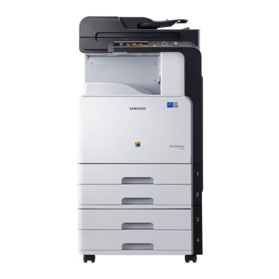
Page 38: Machine External View
Front door Duplex automatic document feeder input tray Front door handle Duplex automatic document feeder output tray Paper output tray Power-switch Control panel Power receptacle Optional dual cassette feeder right bottom door 2-24 Copyright© 1995-2013 SAMSUNG. All rights reserved. - Page 39 2. Product Specifications and Description 2) Front View2 Scanner glass White sheet Multi-purpose tray Multi-purpose tray paper width guide USB port Copyright© 1995-2013 SAMSUNG. All rights reserved. 2-25...
- Page 40 2. Product Specifications and Description 3) Rear View DADF Cable Network Port USB Port USB Printer Port 2-26 Copyright© 1995-2013 SAMSUNG. All rights reserved.
- Page 41 2. Product Specifications and Description 4) Inner view LSU window cleaning stick Waste toner container Toner Cartridges Imaging units Copyright© 1995-2013 SAMSUNG. All rights reserved. 2-27...
-
Page 42: Feeding System
The feeding system picks up a paper from the cassette or MP tray and transports it to the machine inside. It mainly consists of the pick up unit, registration unit, transfer roller Assy, Exit unit. 2-28 Copyright© 1995-2013 SAMSUNG. All rights reserved. -
Page 43: Main Components And Functions
Tray 4 pick up / reverse / forward rollers (Option) Tray 4 Paper tray(Option) MP Tray pick up / reverse / forward rollers Tray 1 pick up / reverse / forward rollers Tray 1 feed roller Copyright© 1995-2013 SAMSUNG. All rights reserved. 2-29... - Page 44 This roller transports the paper sent from the forward/reverse roller to the registration roller. • Registration roller This roller aligns the leading edge of the paper and transports the paper to the transfer roller Assy. 2-30 Copyright© 1995-2013 SAMSUNG. All rights reserved.
- Page 45 2. Product Specifications and Description b) Sensor, Motor, Solenoid Copyright© 1995-2013 SAMSUNG. All rights reserved. 2-31...
- Page 46 MPF(Multi-Purpose Feeder) solenoid Controls MPF pick up roller CN26@ MAIN PBA, 4Pin Tray1 Lift motor Lifting Knock up plate CN27@ MAIN PBA, 10Pin~13Pin Tray2 Lift motor Lifting Knock up plate CN27@ MAIN PBA, 14Pin~17Pin 2-32 Copyright© 1995-2013 SAMSUNG. All rights reserved.
-
Page 47: Cassette (Tray 1,2,3,4)
Tray 2,3,4 : A5, A4, A3, B5, B4, Letter, 11"×17"(Ledger), Statement, Legal 4) Weight : plain paper 60~216 g/m² (16~44 lb) 5) Plate knock up lift type : Lift Motor + Up Limit Sensor Copyright© 1995-2013 SAMSUNG. All rights reserved. 2-33... -
Page 48: Pick-Up Unit
NOTE The Pick-Up Unit1 and Pick-Up Unit2 can’t be swapped over. Pick–Up Unit1 Pick–Up Unit2 2-34 Copyright© 1995-2013 SAMSUNG. All rights reserved. -
Page 49: Registration Unit
The registration(Regi.) roller is driven by the Regi./MP motor. The Regi. clutch is located between the Regi. clutch and Regi./MP motor, and it controls ON/OFF of the registration roller in order to match paper and an image on the drum at the predetermined registration point. Copyright© 1995-2013 SAMSUNG. All rights reserved. 2-35... -
Page 50: Mpf(Multi-Purpose Feeder) Unit
2) Media Size : Max 11. 7” ×17” (297×432 ) / Min 3.87”×5.8” (98×148 ) 3) Media Weight : Plain paper 60 ~ 176 g/m² (16~65lb) 4) Feeding Speed : 30 ppm (CLX-9301 series), 25ppm(CLX–9251 series), 20 ppm (CLX-9201 series) Letter/A4 LEF (Long Edge Feeding) ■... -
Page 51: Image Creation
7) Cleaning and quenching for transfer belt : The cleaning blade clean the belt surface. The grounding roller inside the transfer belt unit removes the remaining charge on the belt. Copyright© 1995-2013 SAMSUNG. All rights reserved. 2-37... -
Page 52: Imaging Unit
Drum units are exchangeable. The diameter of the drum is 30 mm (circumference: about 94.2 mm). The developing gap between a drum and the corresponding magnetic roller cannot be adjusted. The CRUM is the sub part of the Drum unit. It stores the count information and several data. 2-38 Copyright© 1995-2013 SAMSUNG. All rights reserved. -
Page 53: Drum Drive
The BLDC motor maintains the constant speed. So, the speed sync for each color depends on the BLDC motor without the additional device. Phase sync for each OPC runout prints the pattern on the ITB and is adjusted by the data automatically. Copyright© 1995-2013 SAMSUNG. All rights reserved. 2-39... -
Page 54: Developer Unit
The developer in each unit is supplied to the magnetic(development) roller[A] by the two mixing augers[B]. The diameter of the magnetic roller is 16 mm. Each Developer unit has a TC(Toner Concetration) sensor[C]. They are used for controlling the operating range of toner density. 2-40 Copyright© 1995-2013 SAMSUNG. All rights reserved. - Page 55 During development job If the developer unit is stored at temperature above 50°C (122°F), it does not works normally. The toner in developer unit is easy to harden at temperature above 50°C (122°F). Copyright© 1995-2013 SAMSUNG. All rights reserved. 2-41...
-
Page 56: Itb (Intermediate Transfer Belt) Unit
One photo sensor controls the position of the first transfer roller. ITB (Intermediate Transfer Belt) 1st Transfer Roller ITB Drive Roller Tension Roller Photo sensor Cleaning Blade ACR sensor 2nd Transfer Roller Toner Collection Auger Drum Unit 2-42 Copyright© 1995-2013 SAMSUNG. All rights reserved. -
Page 57: Transfer Belt Drive
If the sensor has read an unusually large number of notches or an unusually small number of notches, the controller ignores such unusual signals. Therefore, an incorrect reading does not affect the rotation speed. Copyright© 1995-2013 SAMSUNG. All rights reserved. 2-43... -
Page 58: Transfer Belt Cleaning
The film[D] on the ITB cleaner protects against toner contamination. The driving power by driver roller is transferred to the tension roller[E] and the toner collection auger gear[F] drives the gear[G], and collects the toner. 2-44 Copyright© 1995-2013 SAMSUNG. All rights reserved. -
Page 59: Fuser Unit
4) Non-Contact(NC) Sensor NC sensors (non-contact type thermistors), located near the center and the end of the fusing belt, control the temperature of the fusing belt. Copyright© 1995-2013 SAMSUNG. All rights reserved. 2-45... -
Page 60: Fuser Unit Drive
When the thermostat is triggered, it must be replaced (as well as the other damaged parts in the fuser unit). 2.6.2. Fuser Unit drive The fuser motor[A] drives the pressure roller[B] through the gear train. The fusing belt[C] pressurized by the pressure roller[B] is rotated by driving it. 2-46 Copyright© 1995-2013 SAMSUNG. All rights reserved. -
Page 61: Fuser Unit Temperature Control
If one of the thermostat temperatures becomes higher than 195°C, it opens and cuts power to the fusing lamp. If the other thermostat temperature becomes higher than 195°C, it also opens and cuts power to the fusing lamp. Copyright© 1995-2013 SAMSUNG. All rights reserved. 2-47... -
Page 62: Laser Scanning Unit (Lsu)
Also, the LSU has a skew adjustment function which adjusts the scanning line and the shutter device to protect the glass on the LSU optical path from the contamination. LD PBA Shutter P/Mirror Motor PD PBA F1 Lens F2 Lens Skew Adjust Assy 2-48 Copyright© 1995-2013 SAMSUNG. All rights reserved. -
Page 63: Laser Scanning Optical Path
IC : for Single LD driving IC : for Single LD P/Motor speed 27,874 rpm 34016 rpm Process speed 118 mm/sec 144 mm/sec H/W interface Interface with machine : 50 Interface with machine : 50 FFC cable Copyright© 1995-2013 SAMSUNG. All rights reserved. 2-49... -
Page 64: Laser Synchronizing Detectors
Hsync. The arrow in the above diagram shows the data scanning direction for each color. Black (& Cyan) and Yellow (& Magenta) use the same polygon motor scanning in opposite directions. 2-50 Copyright© 1995-2013 SAMSUNG. All rights reserved. -
Page 65: Automatic Line Position Adjustment
The transfer belt-cleaning unit cleans the transfer belt after the patterns are measured. • KK, CC, MM, YY: Spaces between two lines of the same color. • KC, KM, KY: Spaces between a black line and each color line. Copyright© 1995-2013 SAMSUNG. All rights reserved. 2-51... - Page 66 1) When the machine detects a new drum unit or developer unit, line position adjustment is automatically performed. ITB replaced : 1) When the machine detects a new ITB or other ITB, SVC engineer have to execute the adjustment manually. 2-52 Copyright© 1995-2013 SAMSUNG. All rights reserved.
- Page 67 Skew adjustment assembly[A] consists of the worm gear[1] for adjustment and worm gear[2]. When ACR executes, it detects and adjusts the scanning line slope manually. Skew adjustment assembly[A] for magenta, cyan, and yellow adjusts the skew angle of the F2 lens[B]. This mechanism corrects main scan skew. Copyright© 1995-2013 SAMSUNG. All rights reserved. 2-53...
-
Page 68: Shutter Mechanism
Shutter off : Printing is impossible. Shutter door is closed. Waste toner container is not installed. • Shutter on : Printing is possible. Shutter door is opened. Waste toner container is installed. When the shutter is not on at printing, the LSU Unit Failure error will occur. 2-54 Copyright© 1995-2013 SAMSUNG. All rights reserved. -
Page 69: Drive System
Feed 1 / 2 Roll driving Pick-Up PM-STEP Pick-Up Roll / CST Lift driving (Reverse driving at CST Lift driving) Toner supply Toner transfer in toner cartridge driving Duct OPC / DEVE BLDC OPC/DEVE driving Copyright© 1995-2013 SAMSUNG. All rights reserved. 2-55... - Page 70 2. Product Specifications and Description Motor Motor type Function BLDC ITB driving T1 Dis/En PM-STEP T1 Dis/Engage Waste toner container PM-STEP Waste toner container leveling 2-56 Copyright© 1995-2013 SAMSUNG. All rights reserved.
-
Page 71: Main Drive Unit (Opc, Deve, Itb, T1 Dis/Eng)
2. Product Specifications and Description 2.8.2. Main Drive Unit (OPC, DEVE, ITB, T1 DIS/ENG) Front View Rear View Copyright© 1995-2013 SAMSUNG. All rights reserved. 2-57... -
Page 72: Pick Up Drive
Pick-up : rotating (Pick-up input) / counter rotating (Cst LIFT input) • 1 Step → rotating → 2 Gear (Pick-up driving) • 1 Step → counter rotating → 3 Gear → 4 Gear → 5 Gear → 6 Gear (CST Lift driving) 2-58 Copyright© 1995-2013 SAMSUNG. All rights reserved. -
Page 73: Regi/ Mp Drive
1 BLDC → 2 Gear → 3 Gear → 4 Clutch / Gear (Regi. driving) • 1 BLDC → 2 Gear → 5 Gear → 6 Gear → 7 Clutch / Gear (MP driving) • Copyright© 1995-2013 SAMSUNG. All rights reserved. 2-59... -
Page 74: Feed Drive
2. Product Specifications and Description 2.8.5. Feed Drive Power Train Feed : HB-STEP driving 1 HB-STEP → 2 Gear → 3 Gear (Feed1 driving) • 1 HB-STEP → 2 Gear → 4 Gear (Feed2 driving) • 2-60 Copyright© 1995-2013 SAMSUNG. All rights reserved. -
Page 75: Fuser/Exit Drive
1 BLDC → Rotation→ 2 Gear → 3 Gear (Fuser driving) • 1 BLDC → Counter rotation → 4 Gear → 5 Gear → 6 Gear (Fuser pressure mode driving) • 7 PM STEP → 8 Gear (Exit driving) • Copyright© 1995-2013 SAMSUNG. All rights reserved. 2-61... -
Page 76: Waste Toner Container Drive
1 DC Motor → 2 Gear RDCN SUPPLY → 5 Gear DUCT (DUCT driving) • 1 DC Motor → 2 Gear RDCN SUPPLY → 3 Gear SUPPLY IDLE → 4 Gear SUPPLY (Bottle driving) • 2-62 Copyright© 1995-2013 SAMSUNG. All rights reserved. -
Page 77: Scanner System
The document is transported on the DADF glass by the DADF operation. Do not use such solvents, as alcohol when cleaning the surface of the DADF glass, as it is coated so as not to be scratched by Document. Copyright© 1995-2013 SAMSUNG. All rights reserved. 2-63... - Page 78 -3 to the lens. HR module is driven by the same scan motor as that of the FR module. The speed and distance are half that of the FR module. 2-64 Copyright© 1995-2013 SAMSUNG. All rights reserved.
- Page 79 The size of an original placed on the glass is instantly detected using the Auto Paper Sensor fixed on the Align-frame. 7) Pulley-Driving The Steel Wire is coiled to this part and rotated by the scan motor. This also transfers the power to move the FR/HR module. Copyright© 1995-2013 SAMSUNG. All rights reserved. 2-65...
-
Page 80: Duplex Automatic Document Feeder(Dadf)
Exit roller Sends an original to the exit tray and forms the duplex reverse path. Feed in roller Feeds an original before scanning. Feed out roller Transfers a scanned original to the exit roller. 2-66 Copyright© 1995-2013 SAMSUNG. All rights reserved. -
Page 81: Electrical Parts Location
(Detect) PHOTO-INTERRUPTER 0604-001393 PBA-ADF (Exit Idle) PHOTO-INTERRUPTER 0604-001393 PBA-ADF (Paper Length) PHOTO-INTERRUPTER 0604-001393 PBA-ADF (Paper Width) PHOTO-INTERRUPTER 0604-001393 PBA-ADF (Exit) BLCD MOTOR 0604-001393 PBA-ADF CLUTCH-ELECTRIC 0604-001393 PBA-ADF (Pick Up) CLUTCH-ELECTRIC 0604-001393 PBA-ADF (Regi) Copyright© 1995-2013 SAMSUNG. All rights reserved. 2-67... -
Page 82: Dadf Drive System
A BLDC motor drives the system for simplex and duplex job. • The Pick up and Regi clutch controls the driving on/off. • The Cam type gear and solenoid is used for duplex reverse. 2-68 Copyright© 1995-2013 SAMSUNG. All rights reserved. -
Page 83: Dadf Original Drive Assembly
Then, the pick-up roller moves down and contacts an original in the tray. • When the Registration sensor detects the paper, the pick up clutch stops. • When the Detect-Sensor detects that the tray is empty, the motor stops and the machine enters stand-by status. Copyright© 1995-2013 SAMSUNG. All rights reserved. 2-69... -
Page 84: Dadf Registration (Regi) Drive Assembly
The ROLLER-FEED and ROLLER-M IDLE SCF make the feeding force by using a spring pressure method. The Motor transfers the paper through interlocking the Roller-Feed in and the Roller-Feed out. At scan, the Motor is driven continually to maintain stable paper transfer. 2-70 Copyright© 1995-2013 SAMSUNG. All rights reserved. -
Page 85: Dadf Exit Drive Assembly
At Duplex Mode, when the motor rotates inversely, the solenoid is on and the GEAR-CAM OUTER and GEAR-EXIT are driven. When the GEAR-EXIT rotates, the solenoid drives the GEAR-CAM and it makes the space between the Roller-Exit and Idle Roller. Copyright© 1995-2013 SAMSUNG. All rights reserved. 2-71... -
Page 86: Hardware Configuration
2. Product Specifications and Description 2.11. Hardware Configuration The CLX-9201/9251/9301 Electrical Circuit System consists of the following : • Main Controller (Main board) • OPE Controller • DADF Controller • HVPS board • SMPS board • FDB board Diagram of the CLX-9201/9251/9301 Series Electrical Circuit OP E 7”... - Page 87 The HVPS board generates high-voltage channels and controls it. The FDB board controls the fuser lamp On/Off. The SMPS board generates the 5V, 24V for system power. Copyright© 1995-2013 SAMSUNG. All rights reserved. 2-73...
- Page 88 2. Product Specifications and Description Circuit Board Locations The following diagrams show the locations of the printer circuit boards: 2-74 Copyright© 1995-2013 SAMSUNG. All rights reserved.
-
Page 89: Main Controller
1Gb p s N/W RGMII CLUTCH HP VC S OLENOID Real Time Co n tro l ENS ORS can /En g in e/Fax NAND DDR3 320GB HVP S LS U 128MB 2.5” Lin u x Copyright© 1995-2013 SAMSUNG. All rights reserved. 2-75... - Page 90 OPC PHASE FUSER DRAWER DCF I/F ITB ENCODER FINISHER I/F SCAN GIGA RJ45 LSU JOINT MSOK I/F USH HOST JACK HVPS I/F FAX JOINT USB DEVICE JACK TC SENSOR SIDE HVPS Power CASSETTE 2-76 Copyright© 1995-2013 SAMSUNG. All rights reserved.
- Page 91 Information Part Code : JC92-02429A NOTE This main board is for all models of the CLX-9201/9251/9301 series Part Name : PBA-MAIN 3) Master System Operation Key (MSOK) MSOK PBA is used to store all system information and consists of serial flash memory, a EEPROM and a X-CRUM.The flash memory(4MByte), EEPROM(256Kbit) and X-CRUM are used for all system operation(system parameter, device status, tech information, and service information).
- Page 92 The FDI Module as a option is used to track machine usage such as the number of print or copy pages for some special users. This module interfaces to the main board. • Information Part Code : JC92-01616A PBA name : PBA-SUB FDI • Connection Connector to Main controller 2-78 Copyright© 1995-2013 SAMSUNG. All rights reserved.
-
Page 93: Operation Panel (Ope) Controller
7 inch touch LCD(800x480). The AM3715 is used to interface with users through the touch screen and some buttons. The AM3715 supports the Graphic Accelation for better UI. 1) OPE controller diagram Copyright© 1995-2013 SAMSUNG. All rights reserved. 2-79... - Page 94 2. Product Specifications and Description 2) OPE MAIN PBA • Information Part Code : JC92–02436A NOTE This board is for all models of the CLX-9201/9251/9301 series Part Name : OPE MAIN • Connection KEY PBA Interface connector MAIN PBA POWER Interface connector...
- Page 95 3) 7” TFT LCD, TOUCH SCREEN • Information Part Code : JC07–00021A Part Name : LCD/TSP 4) OPE KEY PBA • Information Part Code : JC92–02435A Part Name : OPE KEY • Connection Interface Connector to OPE Main Copyright© 1995-2013 SAMSUNG. All rights reserved. 2-81...
-
Page 96: Adf Pba
Length Sensor 1,2,3 / Width Sensor 1,2 Exit Sensor Exit Idle Sensor BLDC Motor Cover Open Sensor / Regi. Sensor / Detect Sensor Pick up Clutch / Regi. Clutch / Scan Read Sensor 2-82 Copyright© 1995-2013 SAMSUNG. All rights reserved. -
Page 97: Smps (Switching Mode Power Supply) Board
• Information 110V 220V Part Code JC44-00093A JC44-00100C Part Name SMPS Type 5 V1 SMPS Type 5 V2 • Connection INPUT_AC OUTPUT_24V1/2/3/4/5/6 (to DC POWER PBA) SMPS Enable OUTPUT_5V1/2/3/4/S1/S2 (to DC POWER PBA) Copyright© 1995-2013 SAMSUNG. All rights reserved. 2-83... - Page 98 Power 24V Ground +24V2 Power +GND 24V Ground +24V3 Power 24V Ground +24V4 Power 24V Ground DC Output Connector (CN4) PIN Assign PIN Name Description +5V1 Power 5V Ground +5V2 Power 5V Ground 2-84 Copyright© 1995-2013 SAMSUNG. All rights reserved.
-
Page 99: Fuser Drive Board (Fdb)
This board supplies the voltage to Fuser AC, Heater, Main board. • Information 110V 220V SEC CODE JC44-00210A JC44-00211A PBA NAME FDB V1 FDB V2 • Connection Heater I/F Fuser AC FDB I/F Type 5 Main S/W Inlet Heater S/W Copyright© 1995-2013 SAMSUNG. All rights reserved. 2-85... -
Page 100: Hvps Board
Part Code : JC44–00212A Part Name : HVPS • Connection Ithv Y/M/C/K FUSER HVPS I/F HVPS VOLTAGE DEV Y MHV Y DEV M MHV M DEV C MHV C DEV K MHV K 2-86 Copyright© 1995-2013 SAMSUNG. All rights reserved. -
Page 101: Eraser Pba
The Fuser PBA includes CRU memory for Fuser Unit Life Cycle counting. It also provides a connection interface for the pressure sensor. • Connection Fuser EEPROM, Pressure Sensor I/F Pressure Sensor • Information Part Code : JC92–02470A Part Name : FUSER PBA Copyright© 1995-2013 SAMSUNG. All rights reserved. 2-87... -
Page 102: Waste Sensor Pba
The Deve Crum Joint PBA is the interface PBA between the imaging unit(drum unit and developer unit) and the machine. • Information • Part Code : JC92–02163A • Part Name : DEVE CRUM JOINT 2-88 Copyright© 1995-2013 SAMSUNG. All rights reserved. -
Page 103: Toner Crum Joint Pba
The ITB Encoder PBA provides ITB belt rotation speed information by using a specific photo interrupt sensor (Encoder Sensor). • Information Part Code : JC92–02455A Part Name : ITB ENCODER • Connection ITB Encoder Interface Copyright© 1995-2013 SAMSUNG. All rights reserved. 2-89... -
Page 104: Scan Joint Pba
And it functions as the joint PBA for ADF I/F and 24V, 5V power connectors. • Information Part Code : JC92–02447A Part Name : PBA-SCAN JOINT • Connection MAIN PBA ADF PBA WLED CTL PBA Scan Motor APS Sensor1,2 Home Position Sensor, Cover Open Sensor 2-90 Copyright© 1995-2013 SAMSUNG. All rights reserved. -
Page 105: Charge Coupled Device Module(Ccdm) Pba
ADC converts each analog signal to digital. And for high speed data transmission, the digital data signal is converted to LVDS format with serialization. • Information Part Code : JC92-02458A Part Name : PBA-CCDM • Connection MAIN PBA Copyright© 1995-2013 SAMSUNG. All rights reserved. 2-91... -
Page 106: White-Led(Wled) Ctl Pba
The WLED AL FRONT consists of two WLED used as scanner light. The scanner unit has two WLED AL FRONT PBAs. • Information Part Code : JC92–02460A Part Name : PBA-WLED AL Front • Connection WLED CTL PBA 2-92 Copyright© 1995-2013 SAMSUNG. All rights reserved. -
Page 107: Dcf Unit
Forward Roller (Cassette 3) Retard Roller (Cassette 4) Retard Roller (Cassette 3) Pickup Roller (Cassette 4) Pickup Roller (Cassette 3) Cassette 4 Pickup Assembly 2) Paper path Tray3 paper path Tray4 paper path Copyright© 1995-2013 SAMSUNG. All rights reserved. 2-93... - Page 108 Tray4 feed sensor 0604-001381 CN6 16 to 18 Tray4 limit sensor 0604-001393 CN6 13 to 15 Tray4 paper empty sensor 0604-001393 CN6 10 to 12 Door open sensor JC39-01696A CN3 1 to 2 2-94 Copyright© 1995-2013 SAMSUNG. All rights reserved.
- Page 109 Limit_DCF1_IHCF Tray3 Paper Limit signal Feed_DCF1_IHCF Tray3 Feed signal P_Size_DCF2 Tray4 Paper Size analog signal nP_Empty_DCF2 Tray4 Paper Empty signal Limit_DCF2 Tray4 Paper Limit signal Feed_DCF2 Tray4 Feed signal nDoor_open Door open signal Copyright© 1995-2013 SAMSUNG. All rights reserved. 2-95...
- Page 110 Limit_DCF1_IDCF This sensor detects whether the paper is at pickup position or not. Limit_DCF2_DCF Feed_DCF1_IDCF This sensor detects the leading edge of the paper that is passing on the feed roller. Feed_DCF2_DCF 2-96 Copyright© 1995-2013 SAMSUNG. All rights reserved.
- Page 111 This board has 2 LEDs. The left LED is for checking 5V power supply and the right LED is checking the micom operation. Copyright© 1995-2013 SAMSUNG. All rights reserved. 2-97...
- Page 112 7) Plug and jack location list Connector Connection Number Download tool I/F(Minicube) Debug I/F Cover open Switch (24V interlock Switch) USB I/F EMPTY/LIFT/FEED(Tray3,4) Sensor FEED / PICKUP3,4 Motor Interface with Main Papersize sensor(Tray3,4) 2-98 Copyright© 1995-2013 SAMSUNG. All rights reserved.
-
Page 113: Finisher
Paper Exit roller Tamper Home_F Sensor Jam door Eject Home Sensor Turning Knob Jam Door Open Sensor 2) Paper Path Finisher Main Tray - Staple / Offset Finisher Top Tray – None Staple Copyright© 1995-2013 SAMSUNG. All rights reserved. 2-99... - Page 114 ASSY:PM MOTOR:S2M12T Stacker Moving Motor ASSY:PM MOTOR:S2M12T Rear Tamper Motor ASSY:PM MOTOR:S2M20T SCU Solenoid AS-MOTOR DC EJECTOR Ejector Motor AS-MOTOR PM:Z18:HELICAL Front Tamper Motor AS-MOTOR PM:STAPLER Stapler Cover Solenoid AS-MOTOR PM:STAPLER Push Holder Solenoid 2-100 Copyright© 1995-2013 SAMSUNG. All rights reserved.
- Page 115 CN25 ENGINE Interface Push holder solenoid CN18 Door and Cover Switch CN13 Stapler cover solenoid Stapler unit Tamper/Ejector motors and sensors Feeder/Paddle motors and sensors CN14 SCU solenoid Main tray motor and sensors Copyright© 1995-2013 SAMSUNG. All rights reserved. 2-101...
-
Page 116: Wireless Lan Option
IEEE 802.11 b/g/n compliant Security WEP, WPA-PSK, WMM, WMM-PS, TKIP, and AES hardware acceleration Wi-Fi WPS(Wi-Fi Protected Setup™) compatible Wi-Fi Direct™ compatible NFC (Passive type) Host Interface USB 2.0 Dimension 205.0*145.0*55.0 mm Weight 0.16Kg 2-102 Copyright© 1995-2013 SAMSUNG. All rights reserved. - Page 117 Internal Harness for JC39–01192A [HARNESS-WIRELESS LAN] CLX-9x52/SCX-82x0 NFC Tag JC68–03012A [LABEL ETC-NFC TECTILE STICKER] NFC Guide Sticker JC68–03048A [LABEL VER-INFORMATION] NOTE For installing this option, refer to QIG(Quick Installation Guide). NFC Tag write • Summary Copyright© 1995-2013 SAMSUNG. All rights reserved. 2-103...
- Page 118 3) NFC Tag Writing App (This application will be issued via service bulletin by HQ CS) a) Install the App. b) Run NFC Writer NOTE Please turn on the WiFi before checking WPS-PIN for NFC value c) Search for Wi-Fi Direct printers. Select target printer. 2-104 Copyright© 1995-2013 SAMSUNG. All rights reserved.
- Page 119 Need to insert PIN code if target model supports WFD PIN connection. (NFC model) e) Touch mobile phone to NFC tag, and then it will show “Tag written successfully” message. NOTE If there occurs an error while writing NFC tag, try to touch NFC tag again. Copyright© 1995-2013 SAMSUNG. All rights reserved. 2-105...
- Page 120 2. Product Specifications and Description 2-106 Copyright© 1995-2013 SAMSUNG. All rights reserved.
-
Page 121: Disassembly And Reassembly
3.1.1. Precautions when assembling and disassembling • Use only approved Samsung spare parts. Ensure that part number, product name, any voltage, current or temperature rating are correct. Failure to do so could result in damage to the machine, circuit overload, fire or electric shock. -
Page 122: Releasing Plastic Latches
Many of the parts are held in place with plastic latches. The latches break easily; release them carefully. To remove such parts, press the hook end of the latch away from the part to which it is latched. Copyright© 1995-2013 SAMSUNG. All rights reserved. -
Page 123: Maintenance
2. Clean the sensor window[A] by using a soft cloth. NOTE If you don’t execute “CTD sensor cleaning” menu on SVC mode after cleaning the sensor window, the error message will not disappear. Copyright© 1995-2013 SAMSUNG. All rights reserved. -
Page 124: Cleaning The Lsu Window
2. Take out the LSU window cleaning tool that is located on the front cover. 4. Slowly pull out and push the cleaning tool. 5. Repeat step 4 at least 5 times for each LSU window. Copyright© 1995-2013 SAMSUNG. All rights reserved. -
Page 125: Cleaning The Transfer Roller
1. Open the side cover. 2. Clean the transfer roller[A] by using a soft cloth. 3.2.1.4. Cleaning the scan glass 1. Open the DADF Unit. 2. Clean the scan glass[A] by using a soft cloth. Copyright© 1995-2013 SAMSUNG. All rights reserved. -
Page 126: Replacing The Maintenance Part
3.2.2. Replacing the maintenance part 3.2.2.1. Drum Unit 1. Open the front cover. 3. Turn the green lever counterclockwise. 4. Hold the Drum unit and take it out. 2. Remove the waste toner container. Copyright© 1995-2013 SAMSUNG. All rights reserved. -
Page 127: Developer Unit
And then release the toner supply cap. NOTE It is not possible to change the carriers in developer unit for CLX-9201/9251/9301 series. You must replace the whole Developer Unit. 6. Install the new developer unit. 7. Turn the machine on while the front cover is opened. - Page 128 3. Disassembly and Reassembly 9. Select the “Developer Unit” for all colors that is 11. Close the front cover. replaced. NOTE 10. Push the OK button TC calibration will start. Please wait until warm-up operation is completed. Copyright© 1995-2013 SAMSUNG. All rights reserved.
-
Page 129: Itb Cleaner
2. Loosen a screw. (Note : Less than torque 6kgf.cm) 3.2.2.4. ITB Unit 1. Remove the ITB cleaner. (Refer to 3.2.2.3) 4. Release the left stopper. 2. Open the side cover. 3. Release the right stopper. Copyright© 1995-2013 SAMSUNG. All rights reserved. - Page 130 6. Remove 2 screws. 8. Before install the new ITB unit, align the CAM position. (Align 2 arrows) 9. Install the new ITB unit. And then install the ITB cleaner. (Note : Less than torque 6kgf.cm) 3-10 Copyright© 1995-2013 SAMSUNG. All rights reserved.
-
Page 131: Fuser Unit
1. Open the side cover. 2. Remove the fuser unit after removing 2 screws. 3.2.2.6. Transfer roller 1. Open the side cover. 2. Hold and release the both sides of the transfer roller. Copyright© 1995-2013 SAMSUNG. All rights reserved. 3-11... -
Page 132: Pick-Up_Reverse_Forward Roller
3. Enter SVC mode. Select the menu. (Information > Supply Status > Field Replacement Unit). Push “Reset” button to reset the current count to 0. 3-12 Copyright© 1995-2013 SAMSUNG. All rights reserved. -
Page 133: Mp Pick Up_Reverse_Forward Roller
4. Enter SVC mode. Select the menu. (Information > Supply Status > Field Replacement Unit). Push “Reset” button to reset the current count to 0. Copyright© 1995-2013 SAMSUNG. All rights reserved. 3-13... -
Page 134: Dadf Pick-Up Roller Assy
4. Enter SVC mode. Select the menu. (Information > Supply Status > Field Replacement Unit). Push “Reset” button to reset the current count to 0. 3.2.2.10. DADF friction pad 1. Open the DADF-open cover. 2. Remove the DADF friction pad. 3-14 Copyright© 1995-2013 SAMSUNG. All rights reserved. -
Page 135: Replacing The Main Svc Part
3. Disassembly and Reassembly 3.3. Replacing the main SVC part 3.3.1. Left Cover 1. Remove the left cover after removing 9 screws. 3.3.2. Rear Cover 1. Remove the rear cover after removing 10 screws. Copyright© 1995-2013 SAMSUNG. All rights reserved. 3-15... -
Page 136: Hvps Board
3. Unplug the connector. Remove the HVPS board. 2. Remove 4 screws. Release the middle hook. 3.3.4. Temperature Sensor 1. Remove the left cover. (Refer to 3.3.1) 2. Remove the sensor after unplugging the connector. 3-16 Copyright© 1995-2013 SAMSUNG. All rights reserved. -
Page 137: Lsu
3. Remove the bracket after removing 2 screws. 4. Remove 2 screws. Take out the LSU slowly. CAUTION If you yank the LSU, the LSU harness may be damaged. 5. Unplug the LSU harness from the left. Remove the LSU. Copyright© 1995-2013 SAMSUNG. All rights reserved. 3-17... -
Page 138: Ope Unit
4. Remove 2 screws from the front. 5. Open the side cover. Remove 2 screws. 2. Remove the sticker covering the screw hole. 6. Remove the cover[B]. 3. Remove the cover[A] after removing 2 screws. 3-18 Copyright© 1995-2013 SAMSUNG. All rights reserved. - Page 139 7. Open the DADF unit. Remove 5 screws. 9. Remove 5 screws. 10. Lift up the OPE unit. 11. Turn the OPE unit. Unplug all connectors connecting the machine. 8. Remove the cover [C]. Copyright© 1995-2013 SAMSUNG. All rights reserved. 3-19...
- Page 140 14. Remove the LCD. screws. And then remove the OPE Main PBA. 15. Remove the OPE key PBA. CAUTION Be careful not to damage flat cables. 13. Remove 7 screws. Lift up the OPE bracket. 3-20 Copyright© 1995-2013 SAMSUNG. All rights reserved.
-
Page 141: Main Board
4. Install the new main board and insert the MSOK and memory. NOTE When inserting the MSOK, be careful its direction. CAUTION When re-assembling the main board, be careful of swapping the MAIN BLDC connector[A] and DCF connector[B]. Copyright© 1995-2013 SAMSUNG. All rights reserved. 3-21... -
Page 142: Smps Fan
3. Disassembly and Reassembly 3.3.8. SMPS Fan 1. Remove the rear cover. (Refer to 3.3.2) 2. Unplug the connector. Remove 1 screw. And then remove the SMPS fan. 3-22 Copyright© 1995-2013 SAMSUNG. All rights reserved. -
Page 143: Smps Board
2. Unplug the connector. Remove 4 screws. And then remove the SMPS cover. CAUTION When replacing the FDB board, please wait 5 minutes after unplugging the power cord, then replace it. You can get a shock by the electric discharge. Copyright© 1995-2013 SAMSUNG. All rights reserved. 3-23... -
Page 144: Fuser-Duct Fan
3.3.12. Main board shield 1. Remove the rear cover. (Refer to 3.3.2) 2. Unplug all connectors on the main board. 3. Remove the main board shield after removing 4 screws. 3-24 Copyright© 1995-2013 SAMSUNG. All rights reserved. -
Page 145: Main Drive Unit
Release the harness from the holder. 3.3.14. Fuser/Exit Drive unit 1. Remove the rear cover. (Refer to 3.3.2) 2. Unplug 2 motor connectors. Remove 3 screws. And then remove the Fuser/Exit Drive unit. Copyright© 1995-2013 SAMSUNG. All rights reserved. 3-25... -
Page 146: Pick-Up Drive Unit
2. Unplug the connector. Remove 3 screws. And then Pick-up Drive unit1. 3.3.16. Feed Drive unit 1. Remove the rear cover. (Refer to 3.3.2) 2. Unplug the connector. Remove 3 screws. And then remove the Feed Drive Unit. 3-26 Copyright© 1995-2013 SAMSUNG. All rights reserved. -
Page 147: Regi_Mp Drive Unit
3. Unplug the connector. Remove 2 screws. And then remove the Toner supply drive unit. NOTE • To remove K Toner supply drive unit, first remove the main drive unit. • The toner supply drive units are exchangeable. Copyright© 1995-2013 SAMSUNG. All rights reserved. 3-27... -
Page 148: Waste Toner Container Drive Unit
3. Remove the inner cover after removing 8 screws. 3.3.20. Auto Size sensor 1. Remove all cassettes. See the machine inside. 2. Unplug the connector. Remove 2 screws. And then remove the sensor. 3-28 Copyright© 1995-2013 SAMSUNG. All rights reserved. -
Page 149: Exit Unit
3. Disassembly and Reassembly 3.3.21. Exit Unit 1. Open the side cover. Unplug the Exit unit connector. 2. Remove the Exit unit after removing 3 screws. Copyright© 1995-2013 SAMSUNG. All rights reserved. 3-29... -
Page 150: Side Unit
2. Unplug the side unit connector. CAUTION The spring tension for right stopper is strong. When releasing it, be careful not to hurt yourself. 4. Release the left stopper. 5. Remove the Side Unit. 3-30 Copyright© 1995-2013 SAMSUNG. All rights reserved. -
Page 151: Fuser Out Sensor
1. Remove 2 screws from the both sides. Lift up the 3. Separate the Cover-side exit after removing 3 screws. Cover-side exit. 4. Remove the Fuser out sensor after unplugging the connector. 2. Remove the Cover-side exit after unplugging the connector. Copyright© 1995-2013 SAMSUNG. All rights reserved. 3-31... -
Page 152: Duplex Sensor And Curl Sensor
3. Disassembly and Reassembly 3.3.22.2. Duplex sensor and Curl sensor 1. Remove the transfer roller Assy. 3. Remove the Duplex sensor [A] and Curl sensor [B]. 2. Remove 1 screw. Turn over the Guide-TR Upper. 3-32 Copyright© 1995-2013 SAMSUNG. All rights reserved. -
Page 153: Mp Unit
1. Remove the Harness-Cover [A] after removing 2 4. Remove 3 screws. screws. 5. Remove 1 screw. 2. Remove the Harness-Cover Lower [B] after removing 2 screws. 6. Remove 2 screws. 3. Remove 1 screws. Stand the stopper. Copyright© 1995-2013 SAMSUNG. All rights reserved. 3-33... - Page 154 3. Disassembly and Reassembly 7. Remove 4 screws. 10. Remove 2 screws. 8. Remove the Cover-Side Guide Feed[C]. 11. Unplug the connectors. 9. Lift up the Cover-Side Duplex Lower. 12. Remove the Cover-MP Front. 3-34 Copyright© 1995-2013 SAMSUNG. All rights reserved.
- Page 155 16. Remove the gear [C] after removing the E-ring. 14. Remove the MP Unit. 17. Remove the Bush[D] after removing the E-ring. 15. Remove the MP-cover base. 18. Remove the Bracket-Solenoid after removing 1 screw. Copyright© 1995-2013 SAMSUNG. All rights reserved. 3-35...
- Page 156 3. Disassembly and Reassembly 19. Release the MP bracket pick-up after removing 4 20. Remove the MP solenoid after removing 2 screws. screws. 3-36 Copyright© 1995-2013 SAMSUNG. All rights reserved.
-
Page 157: Fuser Unit
2. Remove the fuser unit after removing 2 screws. 5. Remove the Fuser-Guide Duplex[C] after removing 3 screws. 3. Remove the Frame-Fuser Front[A] after removing 3 screws. 6. Remove the Fuser-Bracket Top after removing 5 screws. Copyright© 1995-2013 SAMSUNG. All rights reserved. 3-37... - Page 158 Be careful not to bend the connector. 11. Lift up the thermostat holder Assy. 9. Remove 2 screws. Unplug the thermostat connector. 12. Remove 3 screws. Lift up and release the thermostat holder. 3-38 Copyright© 1995-2013 SAMSUNG. All rights reserved.
- Page 159 3. Disassembly and Reassembly 15. Straighten the bent thermostat harness. 13. Release the NC sensor. 16. Take out the halogen lamp carefully. 14. Remove 1 screw. Copyright© 1995-2013 SAMSUNG. All rights reserved. 3-39...
-
Page 160: Pick-Up Unit And Sensor
1. Remove the Side Unit. (Refer to 3.3.22) 4. Remove the Feed sensor after unplugging connector. 2. Remove the sensor cover after removing 2 screws. 3. Release the sensor holder after removing 1 screw. 3-40 Copyright© 1995-2013 SAMSUNG. All rights reserved. -
Page 161: Feed Unit
1. Remove the Side Unit. (Refer to 3.3.22) 4. Remove the feed sensor after unplugging the connector. 2. Remove the Feed Unit[A] after removing 1 screw. 3. Remove the bracket[B] after removing 3 screws. Copyright© 1995-2013 SAMSUNG. All rights reserved. 3-41... -
Page 162: Registration Unit
1. Remove the Side Unit. (Refer to 3.3.23) 4. Remove the Regi. sensor after unplugging the connector. 2. Remove the Regi.unit [A] after removing 2 screws. 3. Remove the bracket[B] after removing 3 screws. 3-42 Copyright© 1995-2013 SAMSUNG. All rights reserved. -
Page 163: Dadf Unit
3. Disassembly and Reassembly 3.3.28. DADF Unit 1. Remove the DADF connector cover. 3. Lift up the DADF unit and release it to diagonal direction. 2. Remove 1 screw. Unplug the connector. Copyright© 1995-2013 SAMSUNG. All rights reserved. 3-43... -
Page 164: Dadf Cover
1. Open the Stacker and Cover-Open. Remove 2 screws. 4. Remove the Cover-Deco F. 5. Remove 2 screw. 2. Remove the Cover-Side R by releasing the bottom hooks. 6. Release the hook from the bottom. 3. Remove 3 screws. 3-44 Copyright© 1995-2013 SAMSUNG. All rights reserved. - Page 165 3. Disassembly and Reassembly 7. Remove the Cover-Side F. Copyright© 1995-2013 SAMSUNG. All rights reserved. 3-45...
-
Page 166: Dadf Open Cover
2. Release the Stacker by pushing it and its holder in the opposite direction. 3.3.28.4. DADF main board 1. Remove the Cover-Side R. (Refer to 3.3.28.1) 2. Unplug all connectors on the board. 3. Remove the DADF main board after removing 2 screws. 3-46 Copyright© 1995-2013 SAMSUNG. All rights reserved. -
Page 167: Dadf Motor_Solenoid_Clutch
2. Unplug all connectors on the DADF board. 6. Release the harness holder after removing 2 screw. 3. Remove 1 screw. 7. Unplug the connector. Remove 4 screws. And release 4. Remove 2 screws. the motor. Copyright© 1995-2013 SAMSUNG. All rights reserved. 3-47... - Page 168 3. Disassembly and Reassembly 8. Release the solenoid after removing 2 screws. 10. Remove the clutch. 9. Remove 2 springs. Remove 2 screws. And release the bracket. 3-48 Copyright© 1995-2013 SAMSUNG. All rights reserved.
-
Page 169: Dadf Regi_Cover_Detect Sensor
A : Detect sensor • B : Cover sensor • C : Registration sensor 3.3.28.7. DADF Exit Idle sensor 1. Remove the motor bracket. (Refer to 3.3.28.4) 2. Remove the sensor after unplugging the connector. Copyright© 1995-2013 SAMSUNG. All rights reserved. 3-49... -
Page 170: Dadf Exit Sensor
3. Remove the defective sensor after unplugging the connector. 2. Release the sensor cover after removing 3 screws. • A, B : Paper Length sensor • C, D, E : Paper Width sensor 3-50 Copyright© 1995-2013 SAMSUNG. All rights reserved. -
Page 171: Scanner Unit
3.3.29.1. Scanner joint board 1. Remove the DADF unit. (Refer to 3.3.28) 3. Unplug all connector. Remove 2 screws. And release the scanner joint board. 2. Remove the Scan-Rear cover after removing 7 screws. Copyright© 1995-2013 SAMSUNG. All rights reserved. 3-51... -
Page 172: Scan Glass
3.3.29.2. Scan glass 1. Open and stand the DADF unit at 90 degree angle. 2. Remove 5 screws. 3. Remove the COVER-GLASS and ADF GLASS. 4. Lift up and release the scan glass. 3-52 Copyright© 1995-2013 SAMSUNG. All rights reserved. -
Page 173: Aps Sensor
1. Remove the scan glass. (Refer to 3.3.29.2) 4. Release the APS sensor after remove 2 screws. 2. Remove the align cover after removing 4 screws. 3. Remove 1 screw. Turn over the holder. Copyright© 1995-2013 SAMSUNG. All rights reserved. 3-53... -
Page 174: Fr Module
1. Remove the scan glass. (Refer to 3.3.29.2) 4. Unplug the harness. 2. Remove 2 screws. NOTE Before removing the below screw, mark the current gradation position to tighten the screw in the same position. 3. Release the FR module. 3-54 Copyright© 1995-2013 SAMSUNG. All rights reserved. -
Page 175: Scanner Assy
1. Remove the DADF unit and OPE unit. (Refer to 3.3.7 4. Remove 2 screws from the right. and 3.3.28) 2. Unplug all connectors on the main board. 5. Lift up and release the scanner Assy. 3. Remove 3 screws from the left. Copyright© 1995-2013 SAMSUNG. All rights reserved. 3-55... -
Page 176: Side Cover Open Switch
1. Remove the COVER FRONT TOP[A] and COVER 4. Remove the inner cover. FRONT TOP DECO[B]. (Refer to 3.3.6 OPE unit) 5. Remove the cover open switch. 2. Remove all toner cartridges. 3. Unplug 4 connectors and 8 screws. 3-56 Copyright© 1995-2013 SAMSUNG. All rights reserved. -
Page 177: Replacing The Hdd
3. Remove the COVER-EXIT REAR [C] after removing 5 screws. 2. Remove the Exit-Cover [B]. 4. Remove 4 screws. Unplug the cable. And remove the HDD Assy. 5. Install the new HDD Assy. Copyright© 1995-2013 SAMSUNG. All rights reserved. 3-57... -
Page 178: Dcf (Double Cassette Feeder)
3. Disassembly and Reassembly 3.3.33. DCF (Double Cassette Feeder) 3.3.33.1. DCF main board 1. Remove the Bracket Rear Cover after removing 6 2. Unplug all connectors. Remove 4 screws. And release screws. the DCF main board. 3-58 Copyright© 1995-2013 SAMSUNG. All rights reserved. -
Page 179: Dcf Feed Motor
Feed Drive unit. 3.3.33.3. DCF Pick Up Motor 1. Remove the Bracket Rear Cover after removing 6 2. Unplug the pick up motor connector. Remove 2 screws. screws. And release the DCF pick up motor. Copyright© 1995-2013 SAMSUNG. All rights reserved. 3-59... -
Page 180: Finisher
3.3.34.1. Finisher Main Motor 1. Remove the rear cover after 3 screws. 3. Remove 2 screws. 4. Remove the jam cover. 2. Remove 2 screws. 5. Remove 5 screws 6. Remove the Top-Tray. 3-60 Copyright© 1995-2013 SAMSUNG. All rights reserved. - Page 181 7. Remove the drive gear after removing the E-ring. NOTE 8. Release the exit roller. When reassembling the Top-Tray, check that the suppresser is in right position. 9. Remove the Bottom-Guide after removing 4 screws. Copyright© 1995-2013 SAMSUNG. All rights reserved. 3-61...
- Page 182 3. Disassembly and Reassembly 10. Remove the Main motor after removing 2 screws. 3-62 Copyright© 1995-2013 SAMSUNG. All rights reserved.
-
Page 183: Finisher Board
3. Disassembly and Reassembly 3.3.34.2. Finisher Board 1. Remove the rear cover after removing 3 screws. 2. Disconnect all cables on finisher board. 3. Remove the finisher board after removing 4 screws. Copyright© 1995-2013 SAMSUNG. All rights reserved. 3-63... -
Page 184: Troubleshooting
Start Starts a job. CAUTION When you use the display screen, use your finger only. The screen may be damaged with a sharpen pen or anything else. Copyright© 1995-2013 SAMSUNG. All rights reserved. -
Page 185: Introducing The Display Screen And Useful Buttons
Scan to USB : Enters the Scan to USB menu. When a USB memory device is inserted into the USB memory port on your machine, Scan to USB is activated on the display screen • Machine Setup : You can browse current machine settings or change machine values. Copyright© 1995-2013 SAMSUNG. All rights reserved. -
Page 186: Job Status Button
For detailed information about the eco feature, refer to the Administrator’s Guide. Job Status button When you press the Job Status button, the screen lists the currently running, queued, and completed jobs. Copyright© 1995-2013 SAMSUNG. All rights reserved. -
Page 187: Understanding The Status Led
The toner cartridge, imaging unit, or waste toner container is near the end of its life. Order a new toner cartridge, imaging unit, or waste toner container. You can temporarily improve print quality by redistributing the toner. Copyright© 1995-2013 SAMSUNG. All rights reserved. -
Page 188: Updating Firmware
4) Press the button on control panel in this order. (Machine Setup > Others > Application Management > Application ) 5) Plug the USB flash drive into the USB port. “Install” button will be activated on the Application tab. Press the “Install” button. Copyright© 1995-2013 SAMSUNG. All rights reserved. - Page 189 8) Once the installation is complete, “OK” button will be activated. Press “OK” button. 9) After completing the update, you can find the updated versions at [Machine Setup] > [Machine Details] > [Software Versions]. Copyright© 1995-2013 SAMSUNG. All rights reserved.
-
Page 190: Updating From The Network
1) Go to the SyncThruWeb Service (SWS) main home page. Click [Login] to access as default administrator as shown below. NOTE Login using the Administrator ID and Password established during initial machine setup. 2) Click [Maintenance] on the top menu. And then click [Firmware Upgrade]. Copyright© 1995-2013 SAMSUNG. All rights reserved. - Page 191 4. Troubleshooting 3) Click [Upgrade Wizard]. 4) Click [Browse]. Choose installation file by browsing file system. And click [Next]. 5) The uploading step will start. After this step, next step will be started automatically. Copyright© 1995-2013 SAMSUNG. All rights reserved.
- Page 192 4. Troubleshooting 6) The firmware update will start. 7) Once the installation is complete, the machine power-off and power-on automatically. Copyright© 1995-2013 SAMSUNG. All rights reserved.
-
Page 193: Service Mode (Tech Mode)
To enter the service mode, press 1,2,3 number keys simultaneously. When the password dialog box appears, enter “1934” and press the “OK” button. To exit the service mode, press the “Exit Service” button at the right upper corner of the display. Copyright© 1995-2013 SAMSUNG. All rights reserved. 4-10... -
Page 194: Service Mode Menu Tree
Auto Color Registration Maintenance Print Reports Job Duty Page 4–17 Auto Color Toning History Manual Toning History Usage Counter Full Auto Color Registration RTF Format Export Reports XML Format Page 4–18 PDF Format 4-11 Copyright© 1995-2013 SAMSUNG. All rights reserved. - Page 195 Toner Cartridge OPC Unit Developer Unit Part Developer Replacement Page 4–20 Count Fuser Roller DADF Roller Sheets Delivered to Top Tray Finisher Sheets Delivered to Finishing Tray Page 4–21 Handling Count Finisher Set Count Copyright© 1995-2013 SAMSUNG. All rights reserved. 4-12...
- Page 196 Page 4–39 Manual Color Registration Page 4–40 Normal Auto Tone Adjustment Activation Image Full Management Normal Page 4–41 Auto Tone Adjustment Full Page 4–42 CTD Sensor Cleaning Page 4–42 Print Test Skew Pattern Patterns 4-13 Copyright© 1995-2013 SAMSUNG. All rights reserved.
- Page 197 T1 PWM TR Control Paper Group Page 4–48 Mode Paper Side T2 Control Paper Direction T2 PWM Back up User Data Page 4–49 Management Restore Clear System Cache Enhanced Off/On Security Hibernation Off/Om Copyright© 1995-2013 SAMSUNG. All rights reserved. 4-14...
-
Page 198: Information
Default Threshold Yellow 1~ 30% Magenta 1~ 30% Toner Cyan 1~ 30% Black 1~ 30% Yellow 5 ~ 30% Magenta 5 ~ 30% OPC Unit Cyan 5 ~ 30% Black 5 ~ 30% 4-15 Copyright© 1995-2013 SAMSUNG. All rights reserved. -
Page 199: Software Version
Power Save Hours : It indicates the hours of system power save since the first booting of the system. 4.4.3.5. Fault Log • Information > Fault Log This menu displays faults occurred while the system was operating. Pressing clear button will clear all the save fault log of the system. Copyright© 1995-2013 SAMSUNG. All rights reserved. 4-16... -
Page 200: Print Reports
• If TRC control performs normally, “Pass” count must be non-zero value and “Fail” count must be zero. • If “Fail” count is not zero, the image density sensor needs to be checked. 4-17 Copyright© 1995-2013 SAMSUNG. All rights reserved. -
Page 201: Export Reports
4. Troubleshooting 4.4.3.7. Export Reports • Information > Export Reports This menu exports report to usb stick. Configuration, Error Information, Supplies Information, Usage Counter Reports are exported as the form of selected format. Copyright© 1995-2013 SAMSUNG. All rights reserved. 4-18... -
Page 202: Maintenance Counts
Jam Feed 2 Print Jam Jam Feed 3 (DCF) Feed Jam Jam Feed 4 (DCF) Jam Regi Jam Fuser Out Jam Duplex 1 Jam Duplex 2 Duplex Jam Jam Duplex Regi Jam Duplex Return 4-19 Copyright© 1995-2013 SAMSUNG. All rights reserved. -
Page 203: Part Replacement Count
This menu displays the replacement Counts for the system parts. Users can select one part group and press “OK” to see the exact name of the part along with the occurrence of the replacement. The following table shows groups of the replaceable parts of the system. Copyright© 1995-2013 SAMSUNG. All rights reserved. 4-20... -
Page 204: Finisher Handling Count
“OK” to see a count information. NOTE This menu shall be displayed only if finisher is installed Finisher Handling Count Sheets Delivered to Top Tray Sheets Delivered to Finishing Tray Finisher Set Count 4-21 Copyright© 1995-2013 SAMSUNG. All rights reserved. -
Page 205: Diagnostics
Narrow Paper idling Time2(~185℃) 150/0 109-0160 Cooldown Mode idling Time3 Narrow Paper idling Time3(~195℃) 150/0 109-0170 Cooldown Mode idling Time4 Narrow Paper idling Time4(~205℃) 150/0 109-0180 Cooldown Mode idling Time5 Narrow Paper idling Time5(205~℃) 150/0 Copyright© 1995-2013 SAMSUNG. All rights reserved. 4-22... - Page 206 LSU Skew for Yellow 200 / 0 112-0330 Color Regi LSU Skew Magenta LSU Skew for Magenta 200 / 0 112-0340 Color Regi LSU Skew Cyan LSU Skew for Cyan 200 / 0 4-23 Copyright© 1995-2013 SAMSUNG. All rights reserved.
- Page 207 SMPS Fan Run Start/Stop Deve. Fan run 100-0270 SMPS Fan Run Ready Detects if Deve Fan runs at normal speed. 100-0340 Feed Motor Feed Motor is On/Off 100-0370 Tray1 Pickup Motor Tray1 Motor is On/Off Copyright© 1995-2013 SAMSUNG. All rights reserved. 4-24...
- Page 208 102-0360 Regi. Sensor Detect when a paper is at Regi. sensor. 102-0361 FuserOut Sensor Detect when a paper is at FuserOut sensor. 102-0371 Exit2 Sensor Detect when a paper is at Exit2 sensor. 4-25 Copyright© 1995-2013 SAMSUNG. All rights reserved.
- Page 209 Finisher Left Tamper Motor On/Off 113-0530 Finisher Right Tamper Motor Finisher Right Tamper Motor On/Off 113-0540 Finisher Media Height Solenoid Finisher Media Height Solenoid On/Off 113-0550 Finisher Staple Unit Motor Finisher Staple Unit Motor On/Off Copyright© 1995-2013 SAMSUNG. All rights reserved. 4-26...
- Page 210 Finisher Ejector Motor Finisher Ejector Motor On/Off 113-0570 Finisher Main Tray Motor Finisher Main Tray Motor On/Off 113-0580 Finisher SCU Solenoid Finisher SCU Solenoid On/Off 113-0590 Finisher Safety Cover Solenoid Finisher Safety Cover Solenoid On/Off 4-27 Copyright© 1995-2013 SAMSUNG. All rights reserved.
-
Page 211: Fax Diagnostics
Error Rate 20-530 Dial Tone Detect 20-540 Loop Current Detect 20-550 Busy Signal Detect 20-700 Line Monitor Setting 20-800 Modem Speed 20-810 Fax Transmission Level 20-830 Auto Dial Timeout 20-999 Fax Line Setting Copyright© 1995-2013 SAMSUNG. All rights reserved. 4-28... - Page 212 DMTF 9 Line 20-059 V.34 26400 bps 20-040 V.21 300 bps 20-060 V.34 28800 bps 20-041 V.27ter 2400 bps 20-061 V.34 31200 bps 20-042 V.27ter 4800 bps 20-062 V.34 33600 bps 20-043 V.29 7200 bps 4-29 Copyright© 1995-2013 SAMSUNG. All rights reserved.
-
Page 213: Scanner Diagnostics
05-0000 Pick up Count Pick up Roller Life Count Read Only 05-0010 Document Duplex Reverse Point Document Duplex Reverse Point Read/Write 05-0020 Document Exit Turn Reverse Point Document Exit Turn Reverse Point Read/Write Copyright© 1995-2013 SAMSUNG. All rights reserved. 4-30... - Page 214 Scanner Cover Open/Close Sensor 2 High/Low 06-0020 Scanner Platen Motor Forward Scanner Platen Motor Forward Start/Stop 06-0030 Scanner Platen Motor Backward Scanner Platen Motor Backward Start/Stop Scanner home Sensor Scanner home Sensor High/Low 4-31 Copyright© 1995-2013 SAMSUNG. All rights reserved.
-
Page 215: Adjustment
Print out and check if all the position of scale marks (a, b, e, f) in the image are located within the specified limit. Specification a, b, e, f : 10 mm, ± 1.5 mm Reference Scanner A/S Chart ■ Scanner A/S Chart Front Side Back Side Copyright© 1995-2013 SAMSUNG. All rights reserved. 4-32... - Page 216 2) Check if all the position of scale marks (a, b, e, f) in the image are located within the specified limit. Specification a, b, e, f : 10 mm ± 1.5 mm Reference Scanner A/S Chart 4-33 Copyright© 1995-2013 SAMSUNG. All rights reserved.
- Page 217 3) To check the magnification, compare the length of line “c” of the chart to the copy. Specification a, b : 10 ± 1.5 mm c : 190 ± 1.5 mm Reference A4 Scanner A/S Chart A4 S ca n n e r A/ S Ch a rt Copyright© 1995-2013 SAMSUNG. All rights reserved. 4-34...
- Page 218 : 10 ± 1.5 mm c : 190 ± 1.5 mm Image Position Unit : mm, Scale : 0.1, Min/Max : -6/+6 Magnification Unit : %, Scale: 0.1(0.42mm), Min/Max: 99/101 Reference A4 Scanner A/S Chart 4-35 Copyright© 1995-2013 SAMSUNG. All rights reserved.
- Page 219 3) To check the magnification, compare the length of line “c” of the chart to the copy. Specification a, b : 10 ± 1.5 mm c : 190 ± 1.5 mm Reference A4 Scanner A/S Chart Copyright© 1995-2013 SAMSUNG. All rights reserved. 4-36...
- Page 220 : 10 ± 1.5 mm c : 190 ± 1.5 mm Image Position Unit : mm, Scale : 0.1, Min/Max : -6/+6 Magnification Unit : %, Scale : 0.1(0.42mm), Min/Max : 99/101 Reference A4 Scanner A/S Chart 4-37 Copyright© 1995-2013 SAMSUNG. All rights reserved.
-
Page 221: Acs (Auto Color Sensing)
Copy the ‘mono copied’ original with auto color mode and check if print out is monochrome. Specification Level 1 Level 2 Level 3 Level 4 Level 5 Color 0.5% 0.05% 0.1% 0.25% 0.01% Coverage Reference Copyright© 1995-2013 SAMSUNG. All rights reserved. 4-38... -
Page 222: Image Management
X offset of M in Right • X offset of C in Right • • Y offset of Y in Center • Y offset of M in Center • Y offset of C in Center 4-39 Copyright© 1995-2013 SAMSUNG. All rights reserved. - Page 223 Range : [-5 ~ 5] • Unit : dot • Default : 0 Verification Compare the original with a copy after an execution of Manual Color Registration. Specification Reference Incorrect Color Registration in the troubleshooting chapter Copyright© 1995-2013 SAMSUNG. All rights reserved. 4-40...
- Page 224 Verification Print out a test job and make sure the image quality has recovered. Specification Default Min. Value Max. Value Page Count 5000 Time Left Alone Reference Refer to 4.6.6 Light Image 4-41 Copyright© 1995-2013 SAMSUNG. All rights reserved.
- Page 225 On : Full TRC Control Enable • Off : Full TRC Control Disenable Verification Print out a test job and make sure the image quality has recovered. Specification Reference Refer to 4.6.6 Light Image Copyright© 1995-2013 SAMSUNG. All rights reserved. 4-42...
- Page 226 Purpose To solve the “CTD Sensor Failure” error. NOTE Refer to the troubleshooting for error “A3–2113” Operation Procedure 1) Clean the ACR/CTD sensor. 2) Enter the SVC mode. Execute the CTD Sensor cleaning. 4-43 Copyright© 1995-2013 SAMSUNG. All rights reserved.
-
Page 227: Service Functions
Up” while the total will be 300 impression if the configuration is set to “2 Count Up”. 4.4.6.4. Toner Save • Service Functions > Toner Save This function reduces the use of toner up to 30% and only applies to monochrome printing. Copyright© 1995-2013 SAMSUNG. All rights reserved. 4-44... -
Page 228: Port
1) Connect USB memory to device. 2) Enter service mode by pressing 1 + 2 + 3 buttons. Enter 1934 and OK. 3) Go to "Service Functions > Debug Log" and change debug log level to “DETAILS”. 4-45 Copyright© 1995-2013 SAMSUNG. All rights reserved. - Page 229 5) Once it is completed, the message will be displayed. Then restore the debug log level to ”JOB STATUS”. NOTE If the system log size become considerably huge, it will take longer time to copy to the plugged memory. 6) Check is the Log file is created in the USB memory. Copyright© 1995-2013 SAMSUNG. All rights reserved. 4-46...
-
Page 230: System Recovery
Network : This can format the HDD using network. All data except the stored in MSOK will be deleted. b) HDD Repair : This can restore the internal system by checking the HDD error. This is for HDD recovery itself and irrelevant to the user data in device. 4-47 Copyright© 1995-2013 SAMSUNG. All rights reserved. - Page 231 The system will check for the required packages in the USB stick. If all the packages are present in the USB stick then the system will be directed to the confirmation page otherwise an Error page will be displayed with an appropriate error message. • In case of selecting Network option : Copyright© 1995-2013 SAMSUNG. All rights reserved. 4-48...
- Page 232 5) When pushing “Next” button on option selection page, the confirmation page will be displayed. 6) When pushing “Next” button, progress page will be displayed. 7) When completing HDD Recovery or HDD Repair successfully, reboot the machine. 4-49 Copyright© 1995-2013 SAMSUNG. All rights reserved.
-
Page 233: Tr Control Mode
White Spot : Decrease T1 PWM value Blu r Po o r Tr a n s fe r Wh it e Sp o t Verification Print out a test job and make sure the transfer problem has resolved. Copyright© 1995-2013 SAMSUNG. All rights reserved. 4-50... -
Page 234: User Data Management
Note that hard disk format will be performed when the data encryption option is enabled by administrators. NOTE To use this function users need to prepare a USB hard disk that its size is larger than 100GB. 4-51 Copyright© 1995-2013 SAMSUNG. All rights reserved. -
Page 235: Sfe (Special Feature Enablement)
SCX-8123/ CLX-9252/ SCX-8230/ CLX-8640/ 9251/ 9301 8128 9352 8240 8650 SFE Code Title (Polaris (Polaris (Cosmos-R (Cosmos-R (Evergreen) Color) Mono) Color) Mono) Letterhead/Preprinted paper handle Mono Print only mode Copy Speed Print Output Copyright© 1995-2013 SAMSUNG. All rights reserved. 4-52... -
Page 236: Error Code And Troubleshooting
Motor Failure: #A1-2513. Turn off then on. Call for service if the problem A1-2513 Page 4–75 persists Motor Failure: #A1-4310. Turn off then on. Call for service if the problem A1-4310 Page 4–77 persists 4-53 Copyright© 1995-2013 SAMSUNG. All rights reserved. - Page 237 Sensor Failure: #A3-3113. Turn off then on. Call for service if the problem A3-3113 Page 4–86 persists Sensor Failure: #A3-3114. Turn off then on. Call for service if the problem A3-3114 Page 4–86 persists Copyright© 1995-2013 SAMSUNG. All rights reserved. 4-54...
- Page 238 End of life, Replace with new cyan toner cartridge Page 4–95 C1-4140 End of life, Replace with new cyan toner cartridge Page 4–95 C1-4311 Cyan Toner Cartridge Failure: #C1-4311. Install cyan toner cartridge again Page 4–96 4-55 Copyright© 1995-2013 SAMSUNG. All rights reserved.
- Page 239 Page 4–108 C5-1110 Prepare new transfer belt unit Page 4–109 C5-1120 Replace new transfer belt unit Page 4–109 C5-3120 Replace with new Transfer roller. Page 4–110 C6-1120 Replace with new fuser unit Page 4–110 Copyright© 1995-2013 SAMSUNG. All rights reserved. 4-56...
- Page 240 Input System Failure: #H1-1353. Pull Tray 3 out and insert it Page 4–123 H1-1411 Paper jam in Tray 4 Page 4–124 H1-1412 Paper jam in Tray 4 Page 4–124 H1-1417 Paper jam in Tray 4 Page 4–124 4-57 Copyright© 1995-2013 SAMSUNG. All rights reserved.
- Page 241 H2-6729 Finisher Failure: #H2-6729. Check finisher Page 4–135 H2-6730 Finisher Failure: #H2-6730. Check finisher Page 4–135 H2-6731 Finisher Failure: #H2-6731. Check finisher Page 4–135 H2-6732 Staple cartridge is low. Replace it Page 4–136 Copyright© 1995-2013 SAMSUNG. All rights reserved. 4-58...
- Page 242 M2-1333 Check whether the pieces of paper remain in the paper path Page 4–160 M2-1334 Paper jam inside of machine Page 4–160 M2-2111 Paper jam at the top of duplex path Page 4–160 4-59 Copyright© 1995-2013 SAMSUNG. All rights reserved.
- Page 243 S2-2311 Engine System Failure: #S2-2311. Turn off then on Page 4–174 S2-3110 Engine System Failure: #S2-3110. Turn off then on Page 4–174 S2-3114 Engine System Failure: #S2-3114. Turn off then on Page 4–174 Copyright© 1995-2013 SAMSUNG. All rights reserved. 4-60...
- Page 244 Page 4–187 U1-2141 Fuser Unit Failure: #U1-2141. Turn off then on Page 4–189 U1-2142 Fuser Unit Failure: #U1-2142. Turn off then on Page 4–189 U1-2316 Fuser Failure: #U1-2316. Turn off then on Page 4–190 4-61 Copyright© 1995-2013 SAMSUNG. All rights reserved.
- Page 245 U3-3614 Original paper jam in the exit area of scanner Page 4–202 U3-3713 Original paper jam in the exit area of scanner Page 4–202 U3-4210 Top door of scanner is open Page 4–203 Copyright© 1995-2013 SAMSUNG. All rights reserved. 4-62...
-
Page 246: Ax-Xxxx Type Error Code
5) If the connection is OK, turn the machine on. Enter SVC mode. Select motor test. (Diagnostics > Engine Diagnostics > Engine Test Routines > 100–0000) Check the motor operation. a) If the motor is not operational, 4-63 Copyright© 1995-2013 SAMSUNG. All rights reserved. - Page 247 If the control signal is abnormal, replace the main board(JC92–02429A). b) If the motor is operational, • Check the Pin Num 8. If the value is abnormal, replace the main board. If the value is normal, replace the harness. Copyright© 1995-2013 SAMSUNG. All rights reserved. 4-64...
- Page 248 5) If the connection is OK, turn the machine on. Enter SVC mode. Select motor test. (Diagnostics > Engine Diagnostics > Engine Test Routines > 100–0120) Check the motor operation. a) If the motor is not operational, 4-65 Copyright© 1995-2013 SAMSUNG. All rights reserved.
- Page 249 If the control signal is abnormal, replace the main board(JC92–02429A). b) If the motor is operational, • Check the Pin Num 8. If the value is abnormal, replace the main board. If the value is normal, replace the harness. Copyright© 1995-2013 SAMSUNG. All rights reserved. 4-66...
- Page 250 3) Remove the rear cover after removing 10 screws. 4) Check if the ITB motor connector is connected correctly. 5) If the connection is OK, turn the machine on. Enter SVC mode. Select motor test. 4-67 Copyright© 1995-2013 SAMSUNG. All rights reserved.
- Page 251 If the control signal is abnormal, replace the main board(JC92–02429A). b) If the motor is operational, • Check the Pin Num 8. If the value is abnormal, replace the main board. If the value is normal, replace the harness. Copyright© 1995-2013 SAMSUNG. All rights reserved. 4-68...
- Page 252 4) Check if the yellow OPC motor connector is connected correctly. 5) If the connection is OK, turn the machine on. Enter SVC mode. Select the yellow OPC motor test. (Diagnostics > Engine Diagnostics > Engine Test Routines > 100–0041) 4-69 Copyright© 1995-2013 SAMSUNG. All rights reserved.
- Page 253 If the control signal is abnormal, replace the main board(JC92–02429A). b) If the motor is operational, • Check the Pin Num 8. If the value is abnormal, replace the main board. If the value is normal, replace the harness. Copyright© 1995-2013 SAMSUNG. All rights reserved. 4-70...
- Page 254 4) Check if the magenta OPC motor connector is connected correctly. 5) If the connection is OK, turn the machine on. Enter SVC mode. Select the magenta OPC motor test. (Diagnostics > Engine Diagnostics > Engine Test Routines > 100–0042) 4-71 Copyright© 1995-2013 SAMSUNG. All rights reserved.
- Page 255 If the control signal is abnormal, replace the main board(JC92–02429A). b) If the motor is operational, • Check the Pin Num 8. If the value is abnormal, replace the main board. If the value is normal, replace the harness. Copyright© 1995-2013 SAMSUNG. All rights reserved. 4-72...
- Page 256 4) Check if the cyan OPC motor connector is connected correctly. 5) If the connection is OK, turn the machine on. Enter SVC mode. Select the cyan OPC motor test. (Diagnostics > Engine Diagnostics > Engine Test Routines > 100–0043) 4-73 Copyright© 1995-2013 SAMSUNG. All rights reserved.
- Page 257 If the control signal is abnormal, replace the main board(JC92–02429A). b) If the motor is operational, • Check the Pin Num 8. If the value is abnormal, replace the main board. If the value is normal, replace the harness. Copyright© 1995-2013 SAMSUNG. All rights reserved. 4-74...
- Page 258 4) Check if the black OPC motor connector is connected correctly. 5) If the connection is OK, turn the machine on. Enter SVC mode. Select the black OPC motor test. (Diagnostics > Engine Diagnostics > Engine Test Routines > 100–0044) 4-75 Copyright© 1995-2013 SAMSUNG. All rights reserved.
- Page 259 If the control signal is abnormal, replace the main board(JC92–02429A). b) If the motor is operational, • Check the Pin Num 8. If the value is abnormal, replace the main board. If the value is normal, replace the harness. Copyright© 1995-2013 SAMSUNG. All rights reserved. 4-76...
- Page 260 3) If there is a motor noise or the motor is not operational normally, check the following : a) Remove the rear cover. Check if the T1 engage motor in the main drive unit is defective. i) Rotate the motor manually. 4-77 Copyright© 1995-2013 SAMSUNG. All rights reserved.
- Page 261 If the motor is normal, measure the motor signal with DVM. • If the phase output voltage is changed in 0~24V(8~10V), the output value is normal. • If the phase output voltage is not changed to 0 or 24V, replace the main board(JC92-02429A). Copyright© 1995-2013 SAMSUNG. All rights reserved. 4-78...
- Page 262 If 24V power is not generated, • Measure the 24V power on the SMPS board. If the SMPS board(JC44-00100A (220V) / JC44-00093A (110V)) is defective, replace it. • If the SMPS board is normal, replace the main board(JC92–02429A). 4-79 Copyright© 1995-2013 SAMSUNG. All rights reserved.
- Page 263 If 24V power is not generated, • Measure the 24V power on the SMPS board. If the SMPS board(JC44-00100A (220V) / JC44-00093A (110V)) is defective, replace it. • If the SMPS board is normal, replace the main board(JC92–02429A). Copyright© 1995-2013 SAMSUNG. All rights reserved. 4-80...
- Page 264 If 24V power is not generated, • Measure the 24V power on the SMPS board. If the SMPS board(JC44-00100A (220V) / JC44-00093A (110V)) is defective, replace it. • If the SMPS board is normal, replace the main board(JC92–02429A). 4-81 Copyright© 1995-2013 SAMSUNG. All rights reserved.
- Page 265 If 24V power is not generated, • Measure the 24V power on the SMPS board. If the SMPS board(JC44-00100A (220V) / JC44-00093A (110V)) is defective, replace it. • If the SMPS board is normal, replace the main board(JC92–02429A). Copyright© 1995-2013 SAMSUNG. All rights reserved. 4-82...
- Page 266 4) If the connection is OK, Enter SVC mode and execute fan test. (Diagnostics > Engine Diagnostics > Engine Test Routines) • 100-0260 : SMPS Fan Run • 109-0040 : Fuser Fan Run 4-83 Copyright© 1995-2013 SAMSUNG. All rights reserved.
- Page 267 If the Lock signal is 0V continually, check the harness. If the harness is OK, replace the main board. • If the signal value is different from the table above, replace the fan. Copyright© 1995-2013 SAMSUNG. All rights reserved. 4-84...
-
Page 268: A3–2113/4114 Error Code
5) When pop up appears, select the “Yes” button. NOTE a) CTD sensor calibration will start. Then “CTD sensor failure” error will be solved b) If you don’t execute the CTD sensor cleaning in SVC mode, error message persists. 4-85 Copyright© 1995-2013 SAMSUNG. All rights reserved. - Page 269 4) Install the fuser unit after replacing the thermistor. 5) If the error persists, replace the fuser unit (JC91-01063A(220V) / JC91–01064A (110V)). 6) If the error persists after replacing fuser unit, replace the main board(JC92–02429A). Copyright© 1995-2013 SAMSUNG. All rights reserved. 4-86...
- Page 270 2) Open the side cover. Measure the resistance value of the connector at both ends. If the values is not in 10KΩ ± 1% (@ 25 ℃), replace the photo sensor (1404-001417). • 3) If the sensor is normal, replace the main board(JC92-02429A). 4-87 Copyright© 1995-2013 SAMSUNG. All rights reserved.
- Page 271 Measure the resistance value of the connector at both ends. If the value is not in 47.5KΩ ~ 52.5KΩ (@ 25 ℃), replace the sensor(JC93-00486A). 3) If the harness and sensor are normal, replace the main board (JC92-02429A). Copyright© 1995-2013 SAMSUNG. All rights reserved. 4-88...
-
Page 272: Cx-Xxxx Type Error Code
The yellow toner cartridge is at the end of its life. ► Troubleshooting method 1) Open the front cover. 2) Remove the yellow toner cartridge. 3) Install the new yellow toner cartridge (CLT-Y809S) 4) Close the front cover. 4-89 Copyright© 1995-2013 SAMSUNG. All rights reserved. - Page 273 2) Remove the yellow toner cartridge. Shake the toner cartridge horizontally to distribute the toner evenly inside the cartridge. 3) Check if the toner supply pipe is blocked. If it is closed, open it. 4) Close the front cover. Copyright© 1995-2013 SAMSUNG. All rights reserved. 4-90...
- Page 274 ► Error message Yellow toner cartridge is not compatible. Check users guide. ► Symptom Yellow toner cartridge is not compatible. ► Troubleshooting method 1) Replace the yellow toner cartridge with a new one. 4-91 Copyright© 1995-2013 SAMSUNG. All rights reserved.
- Page 275 The magenta toner cartridge is at the end of its life. ► Troubleshooting method 1) Open the front cover. 2) Remove the magenta toner cartridge. 3) Install the new magenta toner cartridge (CLT-M809S) 4) Close the front cover. Copyright© 1995-2013 SAMSUNG. All rights reserved. 4-92...
- Page 276 2) Remove the magenta toner cartridge. Shake the toner cartridge horizontally to distribute the toner evenly inside the cartridge. 3) Check if the toner supply pipe is blocked. If it is closed, open it. 4) Close the front cover. 4-93 Copyright© 1995-2013 SAMSUNG. All rights reserved.
- Page 277 ► Error message Magenta toner cartridge is not compatible. Check users guide. ► Symptom Magenta toner cartridge is not compatible. ► Troubleshooting method 1) Replace the magenta toner cartridge with a new one. Copyright© 1995-2013 SAMSUNG. All rights reserved. 4-94...
- Page 278 The cyan toner cartridge is at the end of its life. ► Troubleshooting method 1) Open the front cover. 2) Remove the cyan toner cartridge. 3) Install the new cyan toner cartridge (CLT-C809S) 4) Close the front cover. 4-95 Copyright© 1995-2013 SAMSUNG. All rights reserved.
- Page 279 2) Remove the cyan toner cartridge. Shake the toner cartridge horizontally to distribute the toner evenly inside the cartridge. 3) Check if the toner supply pipe is blocked. If it is closed, open it. 4) Close the front cover. Copyright© 1995-2013 SAMSUNG. All rights reserved. 4-96...
- Page 280 ► Error message Cyan toner cartridge is not compatible. Check users guide. ► Symptom Cyan toner cartridge is not compatible. ► Troubleshooting method 1) Replace the cyan toner cartridge with a new one. 4-97 Copyright© 1995-2013 SAMSUNG. All rights reserved.
- Page 281 The black toner cartridge is at the end of its life. ► Troubleshooting method 1) Open the front cover. 2) Remove the black toner cartridge. 3) Install the new black toner cartridge (CLT-K809S) 4) Close the front cover. Copyright© 1995-2013 SAMSUNG. All rights reserved. 4-98...
- Page 282 2) Remove the black toner cartridge. Shake the toner cartridge horizontally to distribute the toner evenly inside the cartridge. 3) Check if the toner supply pipe is blocked. If it is closed, open it. 4) Close the front cover. 4-99 Copyright© 1995-2013 SAMSUNG. All rights reserved.
- Page 283 ► Error message Black toner cartridge is not compatible. Check users guide. ► Symptom Black toner cartridge is not compatible. ► Troubleshooting method 1) Replace the black toner cartridge with a new one. Copyright© 1995-2013 SAMSUNG. All rights reserved. 4-100...
- Page 284 (Refer to 3.2.2.1. Drum Unit) 4) Install the new yellow drum unit(CLT-R809). 5) Clean the LSU window. (Refer to 3.2.1.2. Cleaning the LSU window) 6) Install the waste toner container. 7) Close the front cover. 4-101 Copyright© 1995-2013 SAMSUNG. All rights reserved.
- Page 285 2) Remove the waste toner container. 3) Remove the yellow drum unit. Check if the drum unit is compatible with the machine. 4) If the drum unit is not a samsung genuine, replace it with a new one. Copyright© 1995-2013 SAMSUNG. All rights reserved.
- Page 286 (Refer to 3.2.2.1. Drum Unit) 4) Install the new magenta drum unit(CLT-R809). 5) Clean the LSU window. (Refer to 3.2.1.2. Cleaning the LSU window) 6) Install the waste toner container. 7) Close the front cover. 4-103 Copyright© 1995-2013 SAMSUNG. All rights reserved.
- Page 287 2) Remove the waste toner container. 3) Remove the magenta drum unit. Check if the drum unit is compatible with the machine. 4) If the drum unit is not a samsung genuine, replace it with a new one. Copyright© 1995-2013 SAMSUNG. All rights reserved.
- Page 288 (Refer to 3.2.2.1. Drum Unit) 4) Install the new cyan drum unit(CLT-R809). 5) Clean the LSU window. (Refer to 3.2.1.2. Cleaning the LSU window) 6) Install the waste toner container. 7) Close the front cover. 4-105 Copyright© 1995-2013 SAMSUNG. All rights reserved.
- Page 289 2) Remove the waste toner container. 3) Remove the cyan drum unit. Check if the drum unit is compatible with the machine. 4) If the drum unit is not a samsung genuine, replace it with a new one. Copyright© 1995-2013 SAMSUNG. All rights reserved.
- Page 290 (Refer to 3.2.2.1. Drum Unit) 4) Install the new cyan drum unit(CLT-R809). 5) Clean the LSU window. (Refer to 3.2.1.2. Cleaning the LSU window) 6) Install the waste toner container. 7) Close the front cover. 4-107 Copyright© 1995-2013 SAMSUNG. All rights reserved.
- Page 291 2) Remove the waste toner container. 3) Remove the black drum unit. Check if the drum unit is compatible with the machine. 4) If the drum unit is not a samsung genuine, replace it with a new one. Copyright© 1995-2013 SAMSUNG. All rights reserved.
-
Page 292: C5–1110/1120 Error Code
(INFORMATION > Supply Status > Field Replacement Unit > TRANSFER) 6) Select “ITB Roller”. The “RESET” button will be activated. Click “RESET” to clear the ITB count. 7) Exit SVC mode by pushing the home button. 4-109 Copyright© 1995-2013 SAMSUNG. All rights reserved. - Page 293 The life of the fuser unit has expired. ► Troubleshooting method 1) Turn the machine off. 2) Replace the fuser unit(JC91-01063A (220V) /JC91-01064A (110V)). (Refer to 3.2.2.5. Fuser unit) 3) Turn the machine on. Copyright© 1995-2013 SAMSUNG. All rights reserved. 4-110...
- Page 294 7) If the problem persists, replace the fuser unit(JC91–01063A(220V) / JC91–01064A(110V). CAUTION The temperature gets high in the vicinity of the fuser unit. When replacing it, you may get burned. Before replacing it, make sure that fuser unit has cooled. 4-111 Copyright© 1995-2013 SAMSUNG. All rights reserved.
- Page 295 Waste toner container is not installed. Install it. ► Symptom The waste toner container is not installed. ► Troubleshooting method 1) Open the front cover. 2) Remove and reinstall the waste toner container. 3) Close the front cover. Copyright© 1995-2013 SAMSUNG. All rights reserved. 4-112...
- Page 296 5) Turn the machine off then on. 6) If the problem persists, remove and reinstall the yellow developer unit. 7) If the problem persists, replace the yellow developer unit. (Refer to 3.2.2.2. Developer Unit) 4-113 Copyright© 1995-2013 SAMSUNG. All rights reserved.
- Page 297 5) Turn the machine off then on. 6) If the problem persists, remove and reinstall the magenta developer unit. 7) If the problem persists, replace the magenta developer unit. (Refer to 3.2.2.2. Developer Unit) Copyright© 1995-2013 SAMSUNG. All rights reserved. 4-114...
- Page 298 5) Turn the machine off then on. 6) If the problem persists, remove and reinstall the cyan developer unit. 7) If the problem persists, replace the cyan developer unit. (Refer to 3.2.2.2. Developer Unit) 4-115 Copyright© 1995-2013 SAMSUNG. All rights reserved.
- Page 299 5) Turn the machine off then on. 6) If the problem persists, remove and reinstall the black developer unit. 7) If the problem persists, replace the black developer unit. (Refer to 3.2.2.2. Developer Unit) Copyright© 1995-2013 SAMSUNG. All rights reserved. 4-116...
- Page 300 (INFORMATION > Supply Status > Field Replacement Unit > TRANSFER) 6) Select “T2 Roller”. The “RESET” button will be activated. Click “RESET” to clear the T2 Roller count. 7) Exit the SVC mode by pushing the home button. 4-117 Copyright© 1995-2013 SAMSUNG. All rights reserved.
- Page 301 1) Open the side cover. 2) Remove and reinstall the second transfer roller. (Refer to 3.2.2.6. Transfer roller) 3) Close the side cover. 4) If the problem persists, replace the HVPS board(JC44–00212A). (Refer to 3.3.3. HVPS board) Copyright© 1995-2013 SAMSUNG. All rights reserved. 4-118...
-
Page 302: H1-Xxxx Type (Dcf) Error Code
4) If pick up/ reverse/ forward rollers have no problem, check the following. a) Remove the DCF pick up unit1. Check if the feed sensor cable is connected correctly. b) Check if the sensor cable on DCF board is connected correctly. 4-119 Copyright© 1995-2013 SAMSUNG. All rights reserved. - Page 303 7) Check the DCF pick up motor. a) Check if the DCF pick up motor cable is connected correctly. b) If the connection is OK, replace the DCF pick up drive unit(JC93-00442A). (Refer to 3.3.33.3 DCF Pick Up Motor) Copyright© 1995-2013 SAMSUNG. All rights reserved. 4-120...
- Page 304 3) Check if the auto size sensor cable is connected correctly. Unplug and reconnect it. 4) If the connection is OK, replace the auto size sensor(JC93-00018A). 5) If the problem persists, replace the DCF board(JC92-02453A). (Refer to 3.3.33.1. DCF Main Board) 4-121 Copyright© 1995-2013 SAMSUNG. All rights reserved.
- Page 305 Check if the photo sensor in the DCF pick up unit1 is contaminated. If so, clean it. c) If the photo sensor(0604-001393) is defective, replace it. d) If the actuator(JC66-03199A) is defective, replace it. Copyright© 1995-2013 SAMSUNG. All rights reserved. 4-122...
- Page 306 7) If the problem persists, check the following. a) Remove the DCF pick up unit1. b) Check if the photo sensor in the DCF pick up unit1 is contaminated, clean it. c) If the photo sensor(0604-001393) is defective, replace it. 4-123 Copyright© 1995-2013 SAMSUNG. All rights reserved.
- Page 307 5) If the problem persists after checking step 3~4, check the following : a) Remove the DCF pick up unit2. Check if the sensor and actuator are assembled correctly. b) When pushing the pickup lever, check if the pick up rollers are down. Copyright© 1995-2013 SAMSUNG. All rights reserved. 4-124...
- Page 308 7) Check the DCF pick up motor. a) Check if the DCF pick up motor cable is connected correctly. b) If the connection is OK, replace the DCF pick up drive unit(JC93-00442A). (Refer to 3.3.33.3 DCF Pick Up Motor) 4-125 Copyright© 1995-2013 SAMSUNG. All rights reserved.
- Page 309 3) Check if the auto size sensor cable is connected correctly. Unplug and reconnect it. 4) If the connection is OK, replace the auto size sensor(JC93-00018A). 5) If the problem persists, replace the DCF board(JC92-02453A). (Refer to 3.3.33.1. DCF Main Board) Copyright© 1995-2013 SAMSUNG. All rights reserved. 4-126...
- Page 310 Check if the photo sensor in the DCF pick up unit2 is contaminated. If so, clean it. c) If the photo sensor(0604-001393) is defective, replace it. d) If the actuator(JC66-03199A) is defective, replace it. 4-127 Copyright© 1995-2013 SAMSUNG. All rights reserved.
- Page 311 Remove the DCF pick up unit2. b) Check if the photo sensor in the DCF pick up unit2 is contaminated. If so, clean it. c) If the photo sensor(0604-001393) is defective, replace it. Copyright© 1995-2013 SAMSUNG. All rights reserved. 4-128...
- Page 312 Check if I/L-Switch(HARNESS-DCF COVER OPEN)(JC39–01696A) is not operating normally. If it is defective, replace it. b) If the I/L Switch is OK, replace the DCF board(JC92–02453A). (Refer to 3.3.33.1. DCF Main Board) 4-129 Copyright© 1995-2013 SAMSUNG. All rights reserved.
- Page 313 3) Check if the interface connector is connected to the DCF board. If the interface connector(JC39–01690A) is defective, replace it. 4) If the problem persists, replace the DCF board. (Refer to 3.3.33.1. DCF Main Board) Copyright© 1995-2013 SAMSUNG. All rights reserved. 4-130...
-
Page 314: H2-Xxxx (Finisher) Type Error Code
Replace the finisher input sensor(JC81–09686A). (Refer to 3.3.34.1 Finisher Main Motor) iv) Replace the finisher main board(JC81–09692A). (Refer to 3.3.34.2. Finisher Board) b) Check if any debris is present. Please make sure to remove any debris. 4-131 Copyright© 1995-2013 SAMSUNG. All rights reserved. - Page 315 Make sure each gear is not broken. iii) Replace the gear set(JC81-09592A / J81-09593A / JC81-09595A / JC81-09596A). d) Check if any debris is present. Please make sure to remove any debris. Copyright© 1995-2013 SAMSUNG. All rights reserved. 4-132...
- Page 316 Make sure gear set can rotate smoothly. ii) Make sure each gear is not broken. iii) Replace the Eject-Sub Assy. e) Check if any debris existed. Please make sure to remove any debris. 4-133 Copyright© 1995-2013 SAMSUNG. All rights reserved.
- Page 317 Replace the finisher input sensor(JC81–09686A). (Refer to 3.3.34.1 Finisher Main Motor) iv) Replace the finisher main board(JC81–09692A). (Refer to 3.3.34.2. Finisher Board) c) Check if any debris exists. Please make sure to remove any debris. Copyright© 1995-2013 SAMSUNG. All rights reserved. 4-134...
- Page 318 Make sure finisher stapler motor cable is connected well to the main board connector. iii) Replace the finisher stapler(JC81–07376A). iv) Replace the finisher main board(JC81–09692A). (Refer to 3.3.34.2. Finisher Board) d) Check if any debris (staple) exists. Please make sure to remove any debris. 4-135 Copyright© 1995-2013 SAMSUNG. All rights reserved.
- Page 319 Make sure finisher input sensor cable is connected well to the main board connector. iii) Replace the finisher stapler(JC81–07376A). iv) Replace the finisher main board(JC81–09692A). (Refer to 3.3.34.2. Finisher Board) c) Check if any debris (staple) is present. Please make sure to remove any debris. Copyright© 1995-2013 SAMSUNG. All rights reserved. 4-136...
- Page 320 Make sure finisher stapler motor cable is connected well to the main board connector. iii) Replace the finisher stapler(JC81–07376A). iv) Replace the finisher main board(JC81–09692A). (Refer to 3.3.34.2. Finisher Board) d) Check if any debris (staple) is present. Please make sure to remove any debris. 4-137 Copyright© 1995-2013 SAMSUNG. All rights reserved.
- Page 321 Make sure finisher main tray motor cable is connected well to the main tray motor connector. ii) Make sure finisher main tray motor cable is connected well to the main board connector. iii) Replace the finisher main tray motor(JC81–09679A). (Refer to 3.3.34.1 Finisher Main Motor) Copyright© 1995-2013 SAMSUNG. All rights reserved. 4-138...
- Page 322 4. Troubleshooting iv) Replace the finisher main board(JC81–09692A). (Refer to 3.3.34.2. Finisher Board) c) Check if any debris (staple) is present. Please make sure to remove any debris. 4-139 Copyright© 1995-2013 SAMSUNG. All rights reserved.
- Page 323 Make sure the belt is tight in the correct position, if it has a belt. d) Does finisher Main Tray motor gear set work well? i) Make sure gear set can rotate smoothly. ii) Make sure each gear is not broken. Copyright© 1995-2013 SAMSUNG. All rights reserved. 4-140...
- Page 324 4. Troubleshooting iii) Replace the gear set(JC81–9585A / JC81–09586A). e) Check if any debris is present. Please make sure to remove any debris. 4-141 Copyright© 1995-2013 SAMSUNG. All rights reserved.
- Page 325 Replace the finisher stapler cartridge(JC81–08653A). iv) Replace the finisher stapler(JC81–07376A). v) Replace the finisher main board(JC81–09692A). (Refer to 3.3.34.2. Finisher Board) b) Check if any debris is present. Please make sure to remove any debris. Copyright© 1995-2013 SAMSUNG. All rights reserved. 4-142...
- Page 326 ► Error Code H2–6A63 ► Error message Finisher Failure: #H2-6A63. Check finisher. ► Symptom Finisher stapler cartridge is not installed into stapler or Staples are empty. ► Troubleshooting method 1) Replace the finisher stapler(JC81–07376A). 4-143 Copyright© 1995-2013 SAMSUNG. All rights reserved.
-
Page 327: Mx-Xxxx Type Error Code
Check if the harness of pickup unit and feed sensor are connected correctly. 5) If the problem persists, check the pickup unit1. a) Remove the pickup unit and check the actuator and photo-sensor. Copyright© 1995-2013 SAMSUNG. All rights reserved. 4-144... - Page 328 Push the pickup-lever and check if it operates correctly. 6) If the problem persists, replace the pickup drive unit(JC93–00422A) or Pickup unit1(JC93-00511A). (Refer to 3.3.15. Pick-up Drive unit) (Refer to 3.3.24. Pick-up Unit and Sensor) 4-145 Copyright© 1995-2013 SAMSUNG. All rights reserved.
- Page 329 Check if the harness of pickup unit and feed sensor are connected correctly. 5) If the problem persists, check the pickup unit2. a) Remove the pickup unit2 and check the actuator and photo-sensor. Copyright© 1995-2013 SAMSUNG. All rights reserved. 4-146...
- Page 330 Push the pickup-lever and check if it operates correctly. 6) If the problem persists, replace the pickup drive unit2(JC93–00422A) or Pickup unit1(JC93-00512A). (Refer to 3.3.15. Pick-up Drive unit) (Refer to 3.3.24. Pick-up Unit and Sensor) 4-147 Copyright© 1995-2013 SAMSUNG. All rights reserved.
- Page 331 4) If the problem persists, check the Regi/MPdrive unit. a) Enter SVC mode. Execute Regi./MP motor test. (Diagnostics > Engine Diagnostics > Engine Test Routines > 100-0000) b) Remove the rear cover. c) Check if the motor harness is connected correctly. Copyright© 1995-2013 SAMSUNG. All rights reserved. 4-148...
- Page 332 4. Troubleshooting d) If the problem occurs, replace the Regi/MP Drive Unit(JC93–00443A). (Refer to 3.3.17. Regi_MP Drive unit) 4-149 Copyright© 1995-2013 SAMSUNG. All rights reserved.
- Page 333 3) Check if foreign substance or paper is inside the space between Tray1,2. If so, please remove it. 4) If the problem persists, check that the auto size sensor is connected properly. (Refer to 3.3.20. Auto Size sensor) 5) If the problem persists, replace the main board(JC92–02452A). Copyright© 1995-2013 SAMSUNG. All rights reserved. 4-150...
- Page 334 3) Check if foreign substance or paper is inside the space between Tray1,2. If so, please remove it. 4) If the problem persists, check that the auto size sensor is connected properly. (Refer to 3.3.20. Auto Size sensor) 5) If the problem persists, replace the main board(JC92–02452A). 4-151 Copyright© 1995-2013 SAMSUNG. All rights reserved.
- Page 335 8) If the problem persists, check the pickup unit1. (Refer to 3.3.24. Pick-Up Unit and Sensor) a) Check if the photo sensor in the pickup unit1 is defective. b) If the sensor(0604–001393) is defective, replace it. Copyright© 1995-2013 SAMSUNG. All rights reserved. 4-152...
- Page 336 8) If the problem persists, check the pickup unit2. (Refer to 3.3.24. Pick-Up Unit and Sensor) a) Check if the photo sensor in the pickup unit2 is defective. b) If the sensor(0604–001393) is defective, replace it. 4-153 Copyright© 1995-2013 SAMSUNG. All rights reserved.
- Page 337 (Refer to 3.3.24. Pick-Up Unit and Sensor) c) If the photo sensor is contaminated, clean it. d) If the photo sensor is defective, replace it(0604–001393). e) If the actuator is defective, replace it(JC66-03199A). Copyright© 1995-2013 SAMSUNG. All rights reserved. 4-154...
- Page 338 (Refer to 3.3.24. Pick-Up Unit and Sensor) c) If the photo sensor is contaminated, clean it. d) If the photo sensor is defective, replace it(0604–001393). e) If the actuator is defective, replace it(JC66-03199A). 4-155 Copyright© 1995-2013 SAMSUNG. All rights reserved.
- Page 339 2) If paper is loaded but error message has not disappeared, check the following : (Refer to 3.3.22.3. MP unit) a) If the photo sensor is contaminated, clean it. b) If the photo sensor is defective, replace it(0604–001393). c) If the actuator is defective, replace it(JC66-03217A). Copyright© 1995-2013 SAMSUNG. All rights reserved. 4-156...
- Page 340 If the feed motor operation is normal, check the feed 1 sensor. e) If the sensor operation is abnormal, check the harness. f) If the connection is OK, replace the feed sensor(0604-001381). (Refer to 3.3.25. Feed sensor) 4-157 Copyright© 1995-2013 SAMSUNG. All rights reserved.
- Page 341 If the feed motor operation is normal, check the feed 2 sensor. e) If the sensor operation is abnormal, check the harness. f) If the connection is OK, replace the feed sensor 2 (0604-001381). (Refer to 3.3.26. Feed Unit) Copyright© 1995-2013 SAMSUNG. All rights reserved. 4-158...
- Page 342 If the motor operation is normal, check the regi. sensor. e) If the sensor operation is abnormal, check the harness. f) If the connection is OK, replace the regi. sensor (0604-001381). (Refer to 3.3.27. Registration Unit) 4-159 Copyright© 1995-2013 SAMSUNG. All rights reserved.
- Page 343 (Refer to 3.3.27. Registration Unit) b) Check the sensors in the Side Unit. If the harness is normal, replace the defective sensor (0604-001393 (Refer to 3.3.22.1. Fuser out sensor / 3.3.22.2. Duplex sensor and Curl sensor) Copyright© 1995-2013 SAMSUNG. All rights reserved. 4-160...
- Page 344 Remove the JOB-SEPARATOR. Check if the photo sensor is assembled correctly. c) Check if ACTUATOR-EXIT is assembled correctly. If the ACTUATOR-EXIT (JC66-02533A) is deformed or broken, replace it. d) If the photo sensor(0604-001393) is defective, replace it. 4-161 Copyright© 1995-2013 SAMSUNG. All rights reserved.
- Page 345 Remove the JOB-SEPARATOR. Check if the photo sensor is assembled correctly. c) Check if ACTUATOR-EXIT is assembled correctly. If the ACTUATOR-EXIT (JC66-02533A) is deformed or broken, replace it. d) If the photo sensor(0604-001393) is defective, replace it. Copyright© 1995-2013 SAMSUNG. All rights reserved. 4-162...
- Page 346 1) Remove the paper from output bin tray or inner tray. 2) If this error ccurs continually, check the following. a) Check if the bin-full sensor and actuator is assembled correctly. b) Check if the bin-full sensor(0604–001393) is defective. 4-163 Copyright© 1995-2013 SAMSUNG. All rights reserved.
-
Page 347: Sx-Xxxx Type Error Code
(Refer to 3.3.2 Rear Cover) 5) Replace the main board(JC92–02429A). (Refer to 3.3.7 Main Board) NOTE Insert the MSOK to the new main board. 6) Assemble the rear cover. Turn the machine on. Copyright© 1995-2013 SAMSUNG. All rights reserved. 4-164... - Page 348 Remove the fax holder from the main board. c) Measure the voltage of the battery. If the battery is normal, the measured value is over 3V. 3) If the battery is normal, replace the main board(JC92–02429A). 4-165 Copyright© 1995-2013 SAMSUNG. All rights reserved.
- Page 349 (Refer to 3.3.2 Rear Cover) 4) Replace the main board(JC92–02429A). (Refer to 3.3.7 Main Board) NOTE Insert the MSOK to the new main board. 5) Assemble the rear cover. Turn the machine on. Copyright© 1995-2013 SAMSUNG. All rights reserved. 4-166...
- Page 350 1) Check if the HDD is installed correctly. a) Remove the rear cover. (Refer to 3.3.2 Rear Cover) b) Check if the HDD cable is connected correctly. 2) If the problem persistss, replace the HDD(JC59–00035A). (Refer to 3.3.32 HDD) 4-167 Copyright© 1995-2013 SAMSUNG. All rights reserved.
- Page 351 1) Enter SVC mode. Select “System Recovery” in Service Function menu. (Refer to 4.4.6.8 System Recovery) 2) Execute hard disk format and firmware re-installation. (Refer to 4.3. Updating Firmware) 3) If the problem persistss, replace the HDD(JC59–00035A). (Refer to 3.3.32 HDD) Copyright© 1995-2013 SAMSUNG. All rights reserved. 4-168...
- Page 352 1) Enter SVC mode. Select “Hard Disk Maintenance” in Service Function menu. (Refer to 4.4.6.2 Hard Disk Maintenance) 2) Execute hard disk format. 3) If the problem persistss, replace the HDD(JC59–00035A). (Refer to 3.3.32 HDD) 4-169 Copyright© 1995-2013 SAMSUNG. All rights reserved.
- Page 353 1) Remove the rear cover. (Refer to 3.3.2 Rear Cover) 2) Check if the MSOK is inserted correctly. Remove and reinstall it. 3) If the problem persists, replace the main board(JC92–02429A). (Refer to 3.3.7 Main Board) Copyright© 1995-2013 SAMSUNG. All rights reserved. 4-170...
- Page 354 1) Check if the green LED of the network port is on. 2) If not, unplug and reconnect the network cable. 3) If the problem persists, replace the main board(JC92–02429A). (Refer to 3.3.7 Main Board) 4-171 Copyright© 1995-2013 SAMSUNG. All rights reserved.
- Page 355 2) If the problem persistss, turn the machine off again. 3) Remove and disassemble the OPE unit. (Refer to 3.3.6 OPE Unit) 4) Replace the OPE main board(JC92–02436A). 5) Assemble the OPE unit. 6) Turn the machine on. Copyright© 1995-2013 SAMSUNG. All rights reserved. 4-172...
- Page 356 (Refer to 3.3.2 Rear Cover) 4) Check the connection between FDI device and main board. 5) If the FDI device(CLX-KIT10F) is defective, replace it.. 6) If the problem persistss, replace the main board(JC92-02429A). 4-173 Copyright© 1995-2013 SAMSUNG. All rights reserved.
- Page 357 (Machine Setup > General Settings > Image Management > Auto Color Registration) 2) Clean the ACR sensor. (Refer to 3.2.1.1. Cleaning the ACR/CTD sensor window) 3) If the problem persistss, replace the main board(JC92-02429A). Copyright© 1995-2013 SAMSUNG. All rights reserved. 4-174...
- Page 358 1) Close the front cover correctly. 2) Check if the cover open sensor connector is connected properly. Reconnect it. 3) If the sensor is defective, replace it. (Refer to 3.3.30. Side Cover Open Switch.) 4-175 Copyright© 1995-2013 SAMSUNG. All rights reserved.
- Page 359 2) If the problem persists, check the followings. • Check if the ACR sensor is contaminated or defective. Clean the ACR sensor or replace it. • Remove and reinstall the ITB unit. If the problem persists, replace the ITB unit. Copyright© 1995-2013 SAMSUNG. All rights reserved. 4-176...
- Page 360 5) Remove the scan rear cover. Check if all cables on scan joint board are connected correctly. 6) If the connection is OK, replace the scan joint board(JC92-02447A). (Refer to 3.3.29.1. Scanner joint board) 4-177 Copyright© 1995-2013 SAMSUNG. All rights reserved.
- Page 361 3) Remove the scan rear cover. Check if the connector on scan joint board is connected correctly. 4) Remove the DADF rear cover. Check if the connector on DADF board is connected correctly. (Refer to 3.3.28.4. DADF main board) 5) If the connection is OK, replace the DADF board(JC92-02446A). Copyright© 1995-2013 SAMSUNG. All rights reserved. 4-178...
- Page 362 Fax System Failure: #S4-3111. Install fax modem card again ► Symptom Fax card is not installed properly. / Fax card is defective. ► Troubleshooting method 1) Remove and reinstall the fax card. 2) If the fax card is defective, replace it. 4-179 Copyright© 1995-2013 SAMSUNG. All rights reserved.
- Page 363 3) Remove and disassemble the OPE Unit. (Refer to 3.3.6 OPE Unit) 4) Check if the OPE cable is connected to the OPE board correctly. 5) If the connection is OK, replace the main board(JC92–02429A). Copyright© 1995-2013 SAMSUNG. All rights reserved. 4-180...
- Page 364 1) Check if the green LED of the network port is on. 2) If not, unplug and reconnect the network cable. 3) If the problem persists, replace the main board(JC92–02429A). (Refer to 3.3.7 Main Board) 4-181 Copyright© 1995-2013 SAMSUNG. All rights reserved.
- Page 365 2) Select “Networking Setting”. 3) “Log-In”. 4) Select “TCP/IP”. 5) Select the proper item for your machine. 6) Select “IP Setting”. 7) Select the proper item for your machine. 8) Change the IP address. Copyright© 1995-2013 SAMSUNG. All rights reserved. 4-182...
- Page 366 1) Turn the machine off. Re-install the fuser unit, then turn the machine on. 2) If the problem persists, replace the Fuser unit(110V : JC91-01064A, 220V : JC91-01063A). (Refer to 3.2.2.5 Fuser unit) 4-183 Copyright© 1995-2013 SAMSUNG. All rights reserved.
-
Page 367: U1-Xxxx Type (Fuser) Error Code
(Refer to 3.3.23. Fuser unit) a) Check if the Halogen lamp (110V : 4713-001630 / 220V : 4713–001631) is broken or disconnected. b) Check if the AC connection of the Halogen lamp is disconnected or contaminated. Copyright© 1995-2013 SAMSUNG. All rights reserved. 4-184... - Page 368 4) If the problem persists, replace the Fuser unit(110V : JC91-01064A, 220V : JC91-01063A). 5) If the problem persists, replace the Main board(JC92-02429A) or FDB board(110V : JC44-00210A, 220V : JC44-00211A), SMPS(110V : JC44-00093A, 220V : JC44-00100A) 4-185 Copyright© 1995-2013 SAMSUNG. All rights reserved.
- Page 369 (Diagnostics > Engine Diagnostics > Engine Test Routines > 109–0140) unit(110V : JC91–01064A, 220V : JC91–01063A) 3) If the problem persists, replace the Fuser 4) If the problem persists, replace the pressure control unit or cam-motor or Main board(JC92-02452A). Copyright© 1995-2013 SAMSUNG. All rights reserved. 4-186...
- Page 370 (Refer to 3.3.23. Fuser unit) a) Check if the Halogen lamp (110V : 4713-001630 / 220V : 4713–001631) is broken or disconnected. b) Check if the AC connection of the Halogen lamp is disconnected or contaminated. 4-187 Copyright© 1995-2013 SAMSUNG. All rights reserved.
- Page 371 5) If the problem persists, replace the Fuser unit(110V : JC91-01064A, 220V : JC91-01063A). 6) If the problem persists, replace the Main board(JC92-02429A) or FDB board(110V : JC44-00210A, 220V : JC44-00211A), SMPS(110V : JC44-00093A, 220V : JC44-00100A) Copyright© 1995-2013 SAMSUNG. All rights reserved. 4-188...
- Page 372 5) If the problem persists, replace the Fuser unit(110V : JC91-01064A, 220V : JC91-01063A). 6) If the problem persists, replace the Main board(JC92-02429A) or FDB board(110V : JC44-00210A, 220V : JC44-00211A), SMPS(110V : JC44-00093A, 220V : JC44-00100A) 4-189 Copyright© 1995-2013 SAMSUNG. All rights reserved.
- Page 373 Check if the AC connection of the Halogen lamp is disconnected or contaminated. c) Check if the thermistat(4712-001098) is disconnected. d) Check if non-contact type thermistor(1404–001453) is broken. 4) If the problem persists, replace the Fuser unit(110V : JC91-01064A, 220V : JC91-01063A). Copyright© 1995-2013 SAMSUNG. All rights reserved. 4-190...
- Page 374 4. Troubleshooting 5) If the problem persists, replace the Main board(JC92-02429A) or FDB board(110V : JC44-00210A, 220V : JC44-00211A), SMPS(110V : JC44-00093A, 220V : JC44-00100A) 4-191 Copyright© 1995-2013 SAMSUNG. All rights reserved.
- Page 375 (Refer to 3.3.23. Fuser unit) a) Check if the Halogen lamp (110V : 4713-001630 / 220V : 4713–001631) is broken or disconnected. b) Check if the AC connection of the Halogen lamp is disconnected or contaminated. Copyright© 1995-2013 SAMSUNG. All rights reserved. 4-192...
- Page 376 5) If the problem persists, replace the Fuser unit(110V : JC91-01064A, 220V : JC91-01063A). 6) If the problem persists, replace the Main board(JC92-02429A) or FDB board(110V : JC44-00210A, 220V : JC44-00211A), SMPS(110V : JC44-00093A, 220V : JC44-00100A) 4-193 Copyright© 1995-2013 SAMSUNG. All rights reserved.
- Page 377 (Refer to 3.3.23. Fuser unit) a) Check if the Halogen lamp (110V : 4713-001630 / 220V : 4713–001631) is broken or disconnected. b) Check if the AC connection of the Halogen lamp is disconnected or contaminated. Copyright© 1995-2013 SAMSUNG. All rights reserved. 4-194...
- Page 378 5) If the problem persists, replace the Fuser unit(110V : JC91-01064A, 220V : JC91-01063A). 6) If the problem persists, replace the Main board(JC92-02429A) or FDB board(110V : JC44-00210A, 220V : JC44-00211A), SMPS(110V : JC44-00093A, 220V : JC44-00100A) 4-195 Copyright© 1995-2013 SAMSUNG. All rights reserved.
-
Page 379: U2-Xxxx Type (Lsu) Error Code
If the LSU motor does not makes a sound, i) Turn the machine off and open the side cover. Unplug and reconnect the LSU cable. Check that the LSU motor make a sound after turning the machine on. Copyright© 1995-2013 SAMSUNG. All rights reserved. 4-196... - Page 380 Check that the LSU motor make a sound after turning the machine on. iii) If the LSU cable(JC39-01688A) is defective, replace it. Check that the LSU motor make a sound after turning the machine on. iv) If the problem persists, replace the LSU(JC97-04010A). 4-197 Copyright© 1995-2013 SAMSUNG. All rights reserved.
- Page 381 If the LSU cable(JC39-01688A) is defective, replace it. Check that the LSU motor makes a sound after turning the machine on. d) If the problem persists, replace the LSU(JC97-04010A). Copyright© 1995-2013 SAMSUNG. All rights reserved. 4-198...
-
Page 382: U3-Xxxx Type Error Code
3) If the regi sensor is OK, check the scan sensor(0604-001393) and scan actuator(JC66–03210A). If their operation is abnormal, replace the defective part. 4) Check if the regi. clutch operates normally. Check if the clutch cable is connected correctly. If the clutch(JC47–00033A) is defective, replace it. 4-199 Copyright© 1995-2013 SAMSUNG. All rights reserved. - Page 383 2) If this error occurs continually, check the following: a) Check if the Regi. actuator(JC66–03148A) operates normally. b) Check if the Regi. sensor cable is connected correctly. c) If the connection is OK, replace the Regi. sensor(0604-001393). Copyright© 1995-2013 SAMSUNG. All rights reserved. 4-200...
- Page 384 2) If this error occurs continually, check the following: a) Check if the scan actuator(JC66-03210A) operates normally. b) Check if the scan sensor cable is connected correctly. c) If the connection is OK, replace the scan sensor(0604-001393). 4-201 Copyright© 1995-2013 SAMSUNG. All rights reserved.
- Page 385 2) If this error occurs continually, check the following: a) Check if the exit actuator(JC66-03184A) operates normally. b) Check if the exit sensor cable is connected correctly. c) If the connection is OK, replace the exit sensor(0604-001393). Copyright© 1995-2013 SAMSUNG. All rights reserved. 4-202...
- Page 386 Check the DADF cover open sensor(0604-001393) and its harness. If there is a defective part, replace it. b) If both of them are normal, check the Cover-Open Rib. If it is broken, replace the Cover-Open(JC63-03273A). 4-203 Copyright© 1995-2013 SAMSUNG. All rights reserved.
-
Page 387: Image Quality Problems And Solutions
The first step is to generate prints using printable pages embedded in the printer on laser paper. The paper should be from an unopened ream that has been acclimated to room temperature and you should ensure that genuine Samsung Toner is installed in the printer. - Page 388 For checking the reproduction of small text White Gap pattern For checking color to color, color to mono white gap Rulers For checking the magnification error (unit : cm) Rulers For checking the magnification error (unit : inch) 4-205 Copyright© 1995-2013 SAMSUNG. All rights reserved.
- Page 389 How to analysis the defect image See the next flow chart. 1) According to the part remain life, cause can vary. Check the part remain life. 2) Check the defect whether periodic or not. Copyright© 1995-2013 SAMSUNG. All rights reserved. 4-206...
-
Page 390: Vertical Black Band
(Refer to 3.2.2.3.) Scanner unit is contaminated. Wipe the contaminated part surface with a soft cloth. • Scan glass contamination. (Refer to 3.3.29.4.) • Mirror contamination. CAUTION • CCD sensor contamination. Fragile parts! 4-207 Copyright© 1995-2013 SAMSUNG. All rights reserved. -
Page 391: Vertical White Band, Light Band
The Carrier of Developer unit is insufficient. Replace the Developer Unit. Check the toner remain. • • Check the toner layer on Roller-Magnetic of Developer Unit is uniform or not. (Refer to 3.3.2.2.) Copyright© 1995-2013 SAMSUNG. All rights reserved. 4-208... - Page 392 Cause Action The path of laser beam is blocked. Clean the LSU window. Foreign substance is on the LSU window. (Refer to 3.2.1.2.) OPC is scratched. Replace the Drum Unit. (Refer to 3.2.2.1.) 4-209 Copyright© 1995-2013 SAMSUNG. All rights reserved.
-
Page 393: Horizontal Periodic Black Band Or Dot
CR is scratched. (Refer to 3.3.2.1.) Horizontal periodic black band.(CR, 37.7mm) Replace the Drum Unit. • CR is inferior in quality. (Refer to 3.3.2.1.) OPC is damaged. Replace the Drum Unit. (Refer to 3.3.2.1.) Copyright© 1995-2013 SAMSUNG. All rights reserved. 4-210... -
Page 394: Horizontal Periodic Light/Dark Band Or Dot
OPC is damaged by high voltage in a short time. (Refer to 3.3.2.1.) Horizontal periodic light/dark band (Roller-magnetic, Replace the Developer Unit. 31.4mm) (Refer to 3.2.2.2.) • Roller-magnetic is inferior in quality. V-groove of Roller-magnetic surface is not • uniform. 4-211 Copyright© 1995-2013 SAMSUNG. All rights reserved. -
Page 395: Foggy Image
Voltage of OPC is abnormally low. Check the T1 connection in HVPS. • T1 Voltage is abnormally high. Check if T1–roller spring in ITB is connected correctly. Replace HVPS board. (Refer to 3.3.3.) Copyright© 1995-2013 SAMSUNG. All rights reserved. 4-212... -
Page 396: Light Image
• (Refer to 3.3.3.) TC down and Toner spills Replace developer unit. (Refer to 3.2.2.2.) Toner spills by Eraser. Check if Eraser is contaminated. Replace Drum Unit or Developer Unit. (Refer to 3.2.2.2.) 4-213 Copyright© 1995-2013 SAMSUNG. All rights reserved. -
Page 397: Blurred Image
Check if the connection between T2 high voltage terminal and HVPS THV terminal is correct. Check if the connection of HVPS and ITB is correct. If not, replace HVPS or ITB. HVPS operates abnormally. Replace HVPS (Refer to 3.3.3.) Copyright© 1995-2013 SAMSUNG. All rights reserved. 4-214... -
Page 398: Incorrect Color Registration
Clean the ACR sensor. (Refer to 3.2.1.1.) Circumstances is changed. Perform the OPC-ACR. (Refer to 4.4.5.6.) Check if the skew is occurs at the cassette or feeding rollers. Adjust the skew manually. (Refer to 4.7.) 4-215 Copyright© 1995-2013 SAMSUNG. All rights reserved. -
Page 399: Uneven Pitch And Jitter Image
Under 1 mm periodic jitter or horizontal bands has Check if the LSU is assembled correctly. If not, remove occurred. and tighten the screws. (Refer to 3.3.5.) If the problem persists, replace LSU (Refer to 3.3.5.) Copyright© 1995-2013 SAMSUNG. All rights reserved. 4-216... -
Page 400: Skewed Image
Clean or replace the contaminated roller. contaminated or worn out. (Refer to 3.2.2.7.) If the skewed image occurs for copy job, check the Reinstall the DADF unit. DADF installation. Adjust DADF skew. (Refer to 4.8.) 4-217 Copyright© 1995-2013 SAMSUNG. All rights reserved. -
Page 401: Blank Copy
Replace the HVPS board or Main board or LSU. Check if the connection between scan joint board and Reconnect the harness. main board is OK. If the connection is OK, replace the main board. Copyright© 1995-2013 SAMSUNG. All rights reserved. 4-218... -
Page 402: Poor Fusing Performance
The problem persists, replace Fuser unit. Paper is wrapped on the Heating roller. Remove a wrapped paper and print the demo page. If there are some problems on the printout, replace Fuser unit. 4-219 Copyright© 1995-2013 SAMSUNG. All rights reserved. -
Page 403: Stain On The Paper Back Side
(Refer to 3.2.2.6.) Fuser Unit Are the fuser belt and pressure roller Clean the fuser belt and pressure roller. dirty? Check the pressure roller surface is Replace Fuser unit. damaged or scratched. (Refer to 3.2.2.5.) Copyright© 1995-2013 SAMSUNG. All rights reserved. 4-220... -
Page 404: Adjusting The Lsu Skew Error
Skew Data = 200 : No need to adjustment. • Skew Data > 200 : Rotate the driver in a clockwise direction. ex) Skew Data is 213. : 213–200=13 Click CW rotation NOTE 1 Click is equal to 1/7 dot. 4-221 Copyright© 1995-2013 SAMSUNG. All rights reserved. - Page 405 Print the ACR Report. c) Check the [Y] [M] [C] skew error. d) If the value for YMC is in 200±7, complete the skew adjustment. NOTE If value can not meet the target, repeat the step1~3. Copyright© 1995-2013 SAMSUNG. All rights reserved. 4-222...
-
Page 406: Adjusting The Dadf Skew
(1 scale => 0.9 mm skew adjustment) 3) Detach the DADF sponge after adjusting the skew. Place the DADF sponge on platen glass. And then close the DADF unit to stick the sponge. 4-223 Copyright© 1995-2013 SAMSUNG. All rights reserved. -
Page 407: Troubleshooting Guide
Image registration problem occurs after ACR (Auto Color Registration) 4–260 How to handle TRC error & ACR 4–261 Paper Jam occurs due to Registration ROLLER-IDLE of DADF 4–262 Polaris Color - Removing debris from the Developer Unit. 4–263 Copyright© 1995-2013 SAMSUNG. All rights reserved. 4-224... - Page 408 The ADF does not recognize a piece of paper. 4–265 Blur occurs on Color printout 4–266 "toner cartridge is not installed." error occurs 4–267 The soft keyboard window doesn't display in ACR 4–268 4-225 Copyright© 1995-2013 SAMSUNG. All rights reserved.
- Page 409 2) Remove the connector and 1 screw. 3) Lift up and remove the DADF unit. 4) Remove 4 screws from the each hinge unit. And then replace the hinge unit with new one. Copyright© 1995-2013 SAMSUNG. All rights reserved. 4-226...
- Page 410 4. Troubleshooting 5) Reassemble the DADF unit again. • Part Code Information Part Code Description JC97-03995A DADF-HINGE L JC97-03996A DADF-HINGE R 4-227 Copyright© 1995-2013 SAMSUNG. All rights reserved.
- Page 411 1) During job pausing process, keep valid state of pause process. a) Pausing → Paused b) If user press cancel, paused → canceling → canceled. c) If user press continue, paused → resuming → progressing. Copyright© 1995-2013 SAMSUNG. All rights reserved. 4-228...
- Page 412 Replace the toner cartridge with new one. 4) CRUM connection(Modular connector) installation problem a) Open the front cover. Pull out the toner cartridge. b) Check the CRUM connection (Modular connector) is installed properly. 4-229 Copyright© 1995-2013 SAMSUNG. All rights reserved.
- Page 413 6) Bad connection between the main board and the CRUM Joint PBA Check the connection between the main board and the CRUM Joint PBA. If the connection is bad, replace the harness or the CRUM Joint PBA or main board. Copyright© 1995-2013 SAMSUNG. All rights reserved. 4-230...
- Page 414 1) If Login Failure problem is happened and Easy Printer Manager lower than 1.03.45.01 version is installed on customer PC, please update Easy Printer Manager to the latest version (from Download Center of Samsung web site) 2) Launch Easy Printer Manager and check whether ‘Enable Scan from Device Panel’ is checked in the Scan to PC Settings menu.
- Page 415 Symptom : Numeric key pad operation is abnormal. • Cause : The burr direction of the ground OPE is wrong. There is a tendency that the burr pushes the touch screen panel. • Troubleshooting Replace the Ground OPE. Copyright© 1995-2013 SAMSUNG. All rights reserved. 4-232...
- Page 416 3) Remove the fuser unit. And execute the fuser motor test again. 4) If the machine still makes noise, replace the “DRIVE-FUSER EXIT” Assy. Model Part Code CLX-9201/9251/9301 Series JC93-00441A SCX-8123/8128 Series JC93-00449A 5) If not, replace the fuser unit. 4-233 Copyright© 1995-2013 SAMSUNG. All rights reserved.
- Page 417 2) Remove the DADF separation pad then replace it with new one. 3) Remove the Guide Pickup by pressing the side as shown below. 4) Assemble the new Guide Pickup. 5) Update the firmware as the latest version. Copyright© 1995-2013 SAMSUNG. All rights reserved. 4-234...
- Page 418 24V output channel before replacing the SMPS. 5) If Main board and signal is abnormal and all 24V output channels are nearly 0V, inspect the harness, connector and main board. 4-235 Copyright© 1995-2013 SAMSUNG. All rights reserved.
- Page 419 • Cause : User press stop key during scanning. During job pausing process, scanning is completed. • Troubleshooting 1) During job pausing process, lock the state, check whether scanning or printing is completed. Copyright© 1995-2013 SAMSUNG. All rights reserved. 4-236...
- Page 420 Cause : The spring plate of the side cover open sensor is deformed by the deformation of the stopper of the side cover. • Troubleshooting 1) Replace the side cover open sensor Assy or deform the spring plate to normal shape. 4-237 Copyright© 1995-2013 SAMSUNG. All rights reserved.
-
Page 421: Lcd Touch Problem
If there is no problem, “Complete” will appear on LCD and reboot the machine. When making a mistake, start again from the step 1. 2) Check the touch screen panel flat cable connection on UI PBA. 3) If the connection is OK, replace the UI PBA with new one. Copyright© 1995-2013 SAMSUNG. All rights reserved. 4-238... - Page 422 Symptom : Set UI indicates ACR fail message. • Cause : The brokenness of reflection mirror • Troubleshooting 1) Check the assembly condition inside of LSU. 2) If the reflection mirror is deviated, replace the LSU. 4-239 Copyright© 1995-2013 SAMSUNG. All rights reserved.
- Page 423 Cause : LSU motor defect • Troubleshooting 1) Enter the service mode and execute the LSU motor test. 2) If the LSU motor run sound is loud, replace the LSU. 3) If not, check the other unit. Copyright© 1995-2013 SAMSUNG. All rights reserved. 4-240...
- Page 424 Cause : In protected mode, the “RegOpenCurrentUser” function with write authority returns error or access denied. Can not write on the HKEY_CURRENT_USER registry. • Troubleshooting 1) Download the latest driver and install it. 4-241 Copyright© 1995-2013 SAMSUNG. All rights reserved.
- Page 425 1) Check the harness connection. If the harness is not connected correctly, reconnect it. 2) Check the connector 26 & 27 on main board. If the connector has some problem of soldering, replace the main board. Copyright© 1995-2013 SAMSUNG. All rights reserved. 4-242...
- Page 426 Exit actuator is not returned. (Low resetting force of exit actuator spring.) • Troubleshooting 1) Remove the DADF rear cover, DADF front cover, DADF cover-open Assy, Stacker. (Refer to the disassembly chapter in service manual.) 2) Replace the exit actuator spring. 4-243 Copyright© 1995-2013 SAMSUNG. All rights reserved.
- Page 427 Symptom : In Visio program, the setting of paper source is not affected though the paper source of print driver is changed to Tray1, Tray2 etc • Cause : Visio program set the source in application setting. Application setting is have more priority than print driver setting (Another Vendor is same behavior) Copyright© 1995-2013 SAMSUNG. All rights reserved. 4-244...
- Page 428 4. Troubleshooting • Troubleshooting 1) Click the “Page setup” in file menu in Visio application. 2) Click the “Setup” button. 3) Change the Paper source which you want to use. 4-245 Copyright© 1995-2013 SAMSUNG. All rights reserved.
- Page 429 18) Acoustic noise in Fuser unit • Symptom : Acoustic noise from fuser assembly in early stage of printing • Cause : Fuser belt edges is damaged. • Troubleshooting 1) Replace the fuser unit with new one. Copyright© 1995-2013 SAMSUNG. All rights reserved. 4-246...
- Page 430 24V output channel before replacing the SMPS. 5) If Main board and signal is abnormal and all 24V output channels are nearly 0V, inspect the harness, connector and main board. 4-247 Copyright© 1995-2013 SAMSUNG. All rights reserved.
- Page 431 20) HDD makes a loud noise. • Symptom : The Hard Disk Drive makes a loud noise when working. • Cause : HDD itself has defects. • Troubleshooting 1) Replace the HDD with new one. Copyright© 1995-2013 SAMSUNG. All rights reserved. 4-248...
- Page 432 (EDC Mode > Diagnostics > Engine Diagnostics > Engine Test Routine > Feed motor > on/off ) Check the two feed rollers operating status. d) If the feed rollers can not rotate, open the rear cover and check the motor and gears. 4-249 Copyright© 1995-2013 SAMSUNG. All rights reserved.
- Page 433 4. Troubleshooting 2) Check the connection between the main board(CN27) and feed motor. 3) If the problem persists, replace the main board. Copyright© 1995-2013 SAMSUNG. All rights reserved. 4-250...
- Page 434 Surge voltage from the outside may cause the defects. 4) If those components have visible defects, then the main board should be changed. 4-251 Copyright© 1995-2013 SAMSUNG. All rights reserved.
- Page 435 • Symptom : LCD is blinking when turning on the power. • Cause : OPE board defect • Troubleshooting 1) Check assembling the LCD harness. 2) Replace the OPE board with new one. Copyright© 1995-2013 SAMSUNG. All rights reserved. 4-252...
- Page 436 • Troubleshooting 1) Turn off the device. 2) Open side cover. 3) Turn on the device as Power Key of UI is pressed. 4) Complete System Recovery (HDD format) and reboot the device. 4-253 Copyright© 1995-2013 SAMSUNG. All rights reserved.
- Page 437 C8-2210 (Y) / C8-3210 (M) / C8-4210 (C) /C8-5210 (K) • Troubleshooting 1) Download the PRN file from TSP site. (http://tsp.samsung.com > Knowledge > Technical Resource > Troubleshooting Guide > TG-12070009 ) 2) Send the PRN file to the device. ipsend: Ipsend IP_Address CLEAR_TC_CAL_ERROR.prn Usblist2: Usblist2 CLEAR_TC_CAL_ERROR.prn 3) Wait about 10 seconds after sending PRN file.
- Page 438 2) Perform a copy job from the DADF and see if image distortion occurs. Repeat steps 1 and 2 if there is distortion. 3) If image distortion is removed then tighten the hinges’ screws. 4-255 Copyright© 1995-2013 SAMSUNG. All rights reserved.
- Page 439 If you have already done initial setting with these 4 languages, change Time Zone to (GMT) UK and set the date and time again from Machine Setup > General Settings > Date & Time > Date & Time. Copyright© 1995-2013 SAMSUNG. All rights reserved. 4-256...
- Page 440 4) Check the gear of the main drive is changed (damaged) or if there is an alien substance. If the gear is changed (damaged) then replace the main drive. If an alien substance is found then remove it. 5) Replace the imaging unit that causes the problem. 4-257 Copyright© 1995-2013 SAMSUNG. All rights reserved.
- Page 441 Where rear screw is located when it is seen from the rear of device. b) Normally distance between head of screw and Heat Sink is about 1mm. Loosen screw and align FR. Tighten screw and verify alignment with vernier calipers. Copyright© 1995-2013 SAMSUNG. All rights reserved. 4-258...
- Page 442 Symptom : 706 Error(Paper Jam) occurs while using Polaris inner finisher. • Troubleshooting 1) Refer to the guide from the TSP site. (http://tsp.samsung.com > Knowledge > Technical Resource > Troubleshooting Guide > TG-13020002) 4-259 Copyright© 1995-2013 SAMSUNG. All rights reserved.
- Page 443 If the value is 1152 like the above report, ACR cannot be done. LSU need to be replaced. Succeeded or Failed for ACR: [0] → ACR was performed OK [OK] Succeeded or Failed for ACR: [1] → ACR was not performed OK [Fail] Copyright© 1995-2013 SAMSUNG. All rights reserved. 4-260...
- Page 444 Too low - 190: needs to be adjusted counter-clockwise by 10 clicks Too high - 210: needs to be adjusted clockwise by 10 clicks If the value is between 193~217 then it does not need to be adjusted 4-261 Copyright© 1995-2013 SAMSUNG. All rights reserved.
- Page 445 [How to perform above step 4] a) Remove the DADF cover. b) Remove the DADF pick up Assy. c) Use a razor knife to shave the cover area which is binding with the Registration ROLLER-IDLE. Copyright© 1995-2013 SAMSUNG. All rights reserved. 4-262...
- Page 446 2) Disassemble the developer unit cover (pay attention not to destroy lock) Empty developer out on clean paper. 3) Remove lumps with the Jig from mag roller. 4) Pay attention & clean the circled area where oil can cause build-up in the Fuser. 4-263 Copyright© 1995-2013 SAMSUNG. All rights reserved.
- Page 447 DADF power cable fails. • Troubleshooting 1) Reassemble the DADF power cable and if it does not solve the problem, replace the cable (JC39-01867A) 2) Adjust harness and make it fixed with cable tie. Copyright© 1995-2013 SAMSUNG. All rights reserved. 4-264...
- Page 448 Symptom : An original document does not feed when loaded on the ADF. (Scan is started from platen glass.) • Troubleshooting 1) Open the DADF cover-open 2) Pull the DADF pick up Assy to the front. 3) Remove the old STOPPER. 4) Assemble the new STOPPER. 4-265 Copyright© 1995-2013 SAMSUNG. All rights reserved.
- Page 449 6) Decrease the value for each color and see whether the symptom disappears. In this case, [-4] was applied and solved the blur. 7) As there can be variation for each device, change T1, T2 and observe the results. Copyright© 1995-2013 SAMSUNG. All rights reserved. 4-266...
- Page 450 Toner does not fit in the device as the size of the toner container is too small. • Troubleshooting 1) Change the parts below. Toner Catridge Latch(Black) : JC96–08350A Toner Catridge Latch(Cyan) : JC96–08349A Toner Catridge Latch(Magenta) : JC96–08347A Toner Catridge Latch(Yellow) : JC96–08348A 4-267 Copyright© 1995-2013 SAMSUNG. All rights reserved.
- Page 451 The Keyboard type of ACR editbox is set up in the wrong way b) There is no default settings value of the Keyboard. 3) Resolution a) Setting the defined keyboard value. i) Before ii) After 4) Self-solution a) Click editbox when logging in. Copyright© 1995-2013 SAMSUNG. All rights reserved. 4-268...
- Page 452 4. Troubleshooting 4-269 Copyright© 1995-2013 SAMSUNG. All rights reserved.
-
Page 453: System Diagram
5. System Diagram 5. System Diagram CN18 CN34 CN36 CN13 CN35 CN22 CN20 CN15 CN17 CN30 Copyright© 1995-2013 SAMSUNG. All rights reserved. - Page 454 5. System Diagram CN10 CN38 CN12 CN39 CN40 Copyright© 1995-2013 SAMSUNG. All rights reserved.
- Page 455 5. System Diagram CN19 CN26 CN23 CN11 CN25 CN37 Copyright© 1995-2013 SAMSUNG. All rights reserved.
- Page 456 NSENS _EXIT _ IDLE DGND MINICUBE2 nRESET SOF 3_ DEBUG 3 .3V EXIT SENSOR SIF 3_ DEBUG PHOTO DGND NSCKF3 _DEBU INTERRUPTER NSENS _P _EXIT HS_ DEBUG FLMD1 FLMD0 CN10 EXIT SOLENOID 24 V SOLENOID PWM_EXIT _SOL Copyright© 1995-2013 SAMSUNG. All rights reserved.
-
Page 457: Reference Information
To clean the frame and scan glass Black soft cloth To cover the OPC drum Service Install guide, User guide, When installing the machine. Installation Admin guide Software CD When installing the machine. Installation Copyright© 1995-2013 SAMSUNG. All rights reserved. - Page 458 To fix the unit or parts Service Screw, E-Ring • Clamp To form the harness Service Grease To remove the noise by gear. Service G-8050 : JC81–08663A (200g) • SPY272 : JC81–08664A (100g) • Copyright© 1995-2013 SAMSUNG. All rights reserved.
-
Page 459: Glossary
IP addresses to client hosts. Dual Inline Memory Module (DIMM), a small circuit board that holds memory. DIMM stores all DIMM the data within the machine like printing data, received fax data. Copyright© 1995-2013 SAMSUNG. All rights reserved. - Page 460 Hard Disk Drive (HDD), commonly referred to as a hard drive or hard disk, is a non-volatile storage device which stores digitally-encoded data on rapidly rotating platters with magnetic surfaces. Copyright© 1995-2013 SAMSUNG. All rights reserved.
- Page 461 As most faxes consist mostly of white space, this minimizes the transmission time of most faxes. Modified Modified READ (MMR) is a compression method recommended by ITU-T T.6. Copyright© 1995-2013 SAMSUNG. All rights reserved.
- Page 462 Resolution resolution. Server Message Block (SMB) is a network protocol mainly applied to share files, printers, serial ports, and miscellaneous communications between nodes on a network. It also provides an authenticated Interprocess communication mechanism. Copyright© 1995-2013 SAMSUNG. All rights reserved.
- Page 463 (WAP) and any wireless laptop or WPA-PSK desktop devices. WPA-PSK generates a unique key for each session between a wireless client and the associated WAP for more advanced security. Copyright© 1995-2013 SAMSUNG. All rights reserved.
- Page 464 XML Paper Specification (XPS) is a specification for a Page Description Language (PDL) and a new document format, which has benefits for portable document and electronic document, developed by Microsoft. It is an XML-based specification, based on a new print path and a vector-based device-independent document format. Copyright© 1995-2013 SAMSUNG. All rights reserved.
-
Page 465: Polaris Training Frequently Asked Questions
26) Will I lose counter information if the main board is replaced? 27) What is the interchangeable Drum Unit’s advantage? 28) What are the environment test conditions? 29) Do all Polaris models of Polaris support XOA? Copyright© 1995-2013 SAMSUNG. All rights reserved. - Page 466 After charging process, ozone filter collects ozone from developer unit. On the other hand, contact charging type like roller-charging has no need to implement ozone filter, because there is no ozone produced in developer unit. ※ Charging type Reference Service Manual 2.5.2 Imaging Unit 6-10 Copyright© 1995-2013 SAMSUNG. All rights reserved.
- Page 467 EIUL (End of Imaging Unit Life) function in service mode. And then machine will stop after Drum Cartridge's end of life. ※ Polaris Color and Mono each ensures image quality until 50k (Color), 100k (Mono) impressions. Reference Service Manual 2.2.8 Consumables Copyright© 1995-2013 SAMSUNG. All rights reserved. 6-11...
- Page 468 Reference We received inputs that compared to HP auto on/off, Samsung’s Sleep Mode Power does not show much difference. HP CP1025 model specifies under 1W electricity consumption at Auto Off. Samsung CLP-365 also specifies under 1W at Sleep Mode, so there is no real advantages in Power Consumption.
- Page 469 In Toner Save Mode, it is saved up to approximately. 20 % and text only mode may be used by printing after activating Save Mode. Configure Method: Eco Button Press, Default setting change in EPM and SWS. Copyright© 1995-2013 SAMSUNG. All rights reserved. 6-13...
- Page 470 < BLI Mono 6% Pattern > Question What can happen if I add documents to the DADF while it is in use? No.12 Answer It may cause skew or jams to DADF Reference 6-14 Copyright© 1995-2013 SAMSUNG. All rights reserved.
- Page 471 Can you install a 3rd party HDD to these machines? No.14 Answer Since compatibility test has not been performed, it may cause problems to the unit. Samsung does not provide service support for unauthorized modifications to the device. Reference Question For Polaris Mono 23/28 PPM Models, HDD is not a default option.
- Page 472 Polaris Specification : Ledger, A3, Letter, Legal, Oficio, Folio, A3, A4, JIS B5, ISO B5, Executive, A5, Statement, Custom Question Information on CRU, FRU and PM Parts life cycle? No.19 Answer • CLX-9201/9251/9301 series • SCX-8123/8128 series Reference Service Manual 2.2.8 Consumables 6-16 Copyright© 1995-2013 SAMSUNG. All rights reserved.
- Page 473 No, you will not. Life cycle information of machine is recorded on MSOK in a slot of main board. And you should use existing MSOK even after the main board replacement. So life-cycle information is unaffected by main board replacement. ※ MSOK: Master System Operator Key Reference Copyright© 1995-2013 SAMSUNG. All rights reserved. 6-17...
- Page 474 No, you cannot. It is possible to adjust the priority of functions like copy and scan. But it will be made possible by a firmware update. ※ Setting: Machine setup > General Settings > Home Settings > Priority Reference 6-18 Copyright© 1995-2013 SAMSUNG. All rights reserved.
- Page 475 The SATA cable and power cable are shipped with the optional HDD package. So you should assemble those cables on the main board when you install the HDD. Reference Service Manual 3.3.32.1 Installing the HDD Copyright© 1995-2013 SAMSUNG. All rights reserved. 6-19...
- Page 476 CIS, Africa E.Asia, W.Asia, https://gspn2.samsungcsportal.com China, Japan N.America, S.America https://gspn3.samsungcsportal.com This Service Manual is a property of Samsung Electronics © 2013 Samsung Electronics Co.,Ltd. Co.,Ltd. All rights reserved. Any unauthorized use of Manual can be punished under Printed in Korea applicable International and/or domestic law.