Table of Contents
Advertisement
Quick Links
Advertisement
Table of Contents

Related Manuals for Samsung CLX-9252 Series


Summary of Contents for Samsung CLX-9252 Series
- Page 1 A3 Color Copier CLX-9252/9352 series SERVICE MANUAL A3 Color Copier Contents 1. Precautions 2. Product Description 3. Replacement Procedure 4. Service Mode 5. Updating Firmware 6. Preventive Maintenance 7. Troubleshooting 8. System Diagram 9. System Recovery 10. Reference Information...
-
Page 2: Table Of Contents
Contents chapter 1 Precautions 1.1 Safety Warning …………………………………………………… 1-1 1.2 Caution for safety ………………………………………………… 1-2 1.3 ESD Precautions ………………………………………………… 1-5 chapter 2 Product description 2.1 Specifi cations …………………………………………………… 2-1 2.2 System confi guration …………………………………………… 2-9 2.3 Sensor location …………………………………………………… 2-18 2.4 Paper handling section …………………………………………... - Page 3 Contents 2.7.5 Shutter mechanism ………………………………………… 2-49 2.8 Printer Drive system ……………………………………………… 2-50 2.8.1 Drive Motors ………………………………………………… 2-50 2.8.2 Main drive unit (OPC, DEVE, ITB, T1 DIS/ENG) ………… 2-52 2.8.3 Pick-up Drive ………………………………………………… 2-53 2.8.4 MP, Regi and Duplex Drive ………………………………… 2-54 2.8.5 Fuser Exit and Duplex Return Drives ………………………...
- Page 4 Contents 2.11.17 Deve CRUM Joint PBA ………………………………… 2-96 2.11.18 Toner CRUM Joint PBA ………………………………… 2-96 2.11.19 Scan Joint PBA …………………………………………… 2-97 2.11.20 White-LED(WLED) CTL PBA …………………………… 2-98 2.11.21 White-LED(WLED) AL FRONT PBA …………………… 2-98 2.12 Heating cables ………………………………………………… 2-99 chapter 3 Replacement procedure 3.1 General Disassembly Procedure Precautions …………………...
- Page 5 Contents 3.6 Cartridge transfer unit …………………………………………… 3-44 3.7 Main Board ……………………………………………………… 3-48 3.8 Hard Disk Drive (HDD) …………………………………………… 3-50 3.9 SMPS Board ……………………………………………………… 3-51 3.10 FDB (Fuser Drive Board) ……………………………………… 3-52 3.11 HVPS board ……………………………………………………… 3-53 3.12 Lift Motor ………………………………………………………… 3-54 3.13 Toner motor and Toner PBA ……………………………………...
- Page 6 Contents 4.2.3 Diagnostics Tab …………………………………………… 4-4 4.2.4 Service Functions ………………………………………… 4-5 4.3 Information Tab …………………………………………………… 4-6 4.3.1 General ……………………………………………………… 4-6 4.3.2 Supply status ……………………………………………… 4-6 4.3.3 Software version …………………………………………… 4-8 4.3.4 Service Hours ……………………………………………… 4-8 4.3.5 Fault Log …………………………………………………… 4-8 4.3.6 Print reports …………………………………………………...
- Page 7 Contents 4.5.6.2 Full Color Registration ………………………………… 4-47 4.5.6.2 Auto Color Tone Adjustment ………………………… 4-48 4.5.7 TR Contorl Mode …………………………………………… 4-51 4.6 Sevice functions ………………………………………………… 4-52 4.6.1 Main Memory Clear ……………………………………… 4-52 4.6.2 Hard Disk Maintenance …………………………………… 4-52 4.6.3 Debug Log ………………………………………………… 4-52 4.6.4 Port …………………………………………………………...
- Page 8 Contents 6.2.10 DADF friction pad ………………………………………… 6-18 6.2.11 MP Pick up/ Retard/ Forward roller …………………… 6-19 6.3. Cleaning the PM parts ………………………………………… 6-21 6.3.1 Cleaning the charge scorotron …………………………… 6-21 6.3.2 Cleaning the pick up roller ………………………………… 6-22 6.3.3 Cleaning the Regi roller …………………………………… 6-23 6.3.4 Cleaning the tray1 feed roller ………………………………...
- Page 9 Contents 7.4. DADF skew testing ……………………………………………… 7-151 7.5 Other Errors ……………………………………………………… 7-153 chapter 8 System diagram 8.1 Main 1 ……………………………………………………………… 8-1 8.2 Main 2 ……………………………………………………………… 8-2 8.3 Main 3 …………………………………………………………… 8-3 8.4 Main 4 …………………………………………………………… 8-4 8.5 SCAN & DADF …………………………………………………… 8-5 8.6 DADF ………………………………………………………………...
-
Page 10: Safety Warning
High voltages and lasers inside this product are da ngerous. This printer should only be serviced by a qualified service technician. (2) Use only Samsung replacement parts (2) Use only Samsung replacement parts. There are no user serviceable parts inside the print ter. -
Page 11: Caution For Safety
(12) Do not insert any metal objects into the machine th hrough the ventilator fan or other part of the casing, it could make contact with a high voltage conductor inside the machine and cause an electric shock. SAMSUNG ELECTRONICS Service Manual... - Page 12 OPC-ACR surely. 1.2.4 Assembly / Disassembly Precau utions Replace parts carefully and always use Samsung part ts. Take care to note the exact location of parts and cable routing before dismantling any part of the machi ne.
- Page 13 -If you are moving the machine a long distance, you sh hould remove toner & imaging unit, lock scan carrier & staple unit, tape and disassemble all trays. (e.g : m moved by truck or so) SAMSUNG ELECTRONICS Service Manual...
-
Page 14: Esd Precautions
ESDs. Normal motions, such as the brushing together of clothing fabric and lifting on ne’s foot from a carpeted floor, can generate static electricity sufficient to damage an ESD electricity sufficient to damage an ESD. SAMSUNG ELECTRONICS Service Manual... -
Page 15: Product Description
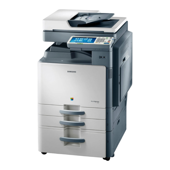
HDD : 320 GB 1.5GB memory Options HCF, DCF, Standard Finisher(1K) Booklet Finisher(3K), Fax etc. kl t Fi i h (3K) F • 8.9” Full color touch LCD CLX-9252/9352 series • XOA(eXtensible Open Architecture) support Service Manual SAMSUNG ELECTRONICS... - Page 16 Note - See the Rating label on th he machine for correct voltage, frequency (hertz) and type heating wire in of current. DCF/HCF The voltage rating of heating wire e is the same as the machine’s voltage rating. Service Manual SAMSUNG ELECTRONICS...
- Page 17 • Color: 8.5 seconds (from ready) Copy resolution • Platen : 600 x 600 dpi • Document feeder: Up to 600 x 6 600 dpi • Platen : 25% to 400% Zoom range • Document feeder: 25% to 400% Service Manual SAMSUNG ELECTRONICS...
- Page 18 98 dpi • Fine : 203 x 196 6 dpi Resolution • Super Fine : 30 0 x 300 dpi • Ultra Fine : 600 x 600 dpi Memory HDD Backup Auto dialer up to 500 numbe Service Manual SAMSUNG ELECTRONICS...
- Page 19 4, B4 SEF, A4, A4 SEF, B5, B5 SEF, A5, A5 SEF • Simplex : 42 ~ 163 gsm (30 0lb Book ~ 90lb Index) Original Weight for DADF • Duplex : 50 ~ 128 gsm (30lb b Book ~ 34lb Bond) Service Manual SAMSUNG ELECTRONICS...
- Page 20 6% ** Image counts are based on one color on each pag e. If you print a document in full color (Yellow, Magenta, Cyan, Black), the number of image is 4 ima ages. Service Manual SAMSUNG ELECTRONICS...
- Page 21 0V, 10W (equipped by service person at field, voltage rating CLX-DHK12C of H of H Heating Wire is the same as the machine’s voltage rating) Heating Wire is the same as the machine s voltage rating) Service Manual SAMSUNG ELECTRONICS...
- Page 22 2/3 hole Punch kit (CLX-HPU000) (CLX HPU000) 2/4 hole Punch kit (CLX-HPU001) Main unit Fax multi-line kit Optional tray High capacity feeder Fax kit (CLX-FAX260) (CLX-PFP000) (CLX-HCF102) (CLX-FAX160) (CLX-D DSK10T) Cassette Heating cable D I kit (CLX-DHK11C/12C) (CLX X-KIT10F) Service Manual SAMSUNG ELECTRONICS...
- Page 23 SCX-STP000 Working Table CLX-WKT000 Job seperator Job seperator SCX JST000 SCX-JST000 FDI Kit CLX-KIT10F CLX-FAX150 Fax Kit CLX-FAX160 CLX-FAX250 Fax Multi Kit CLX-FAX260 CLX-DHK11C Heating Wire for HCF, DCF CLX-DHK12C CLX-DHK11S Heating Wire for Scan CLX-DHK12S Service Manual SAMSUNG ELECTRONICS...
- Page 24 Standard tray (tray 1, tray 2) width guides Duplex automatic document feeder Front door input tray Duplex automatic document feeder Front door handle output tray Standard tray right bottom door Control panel Optional dual cassette feeder right Center tray bottom door Service Manual SAMSUNG ELECTRONICS...
- Page 25 2. Product d description Front view 2 Scanner glass Power-switch White sheet White sheet Power receptacle Power receptacle Multi-purpose tray USB port (2 EA) Multi-purpose tray paper width guide Service Manual SAMSUNG ELECTRONICS...
- Page 26 2. Product d description Rear view Optional dual cassette feeder cable USB host port DADF cable Finisher connector Scanner locking screw Network port Service Manual SAMSUNG ELECTRONICS...
- Page 27 2. Product d description Inner view Waste toner container Imaging units Toner cartridge Inner cover Service Manual SAMSUNG ELECTRONICS...
- Page 28 2. Product d description View with standard finisher (option Standard finisher front door Top door Manual stapler Standard finisher Front door handle Manual stapler button Bridge Unit Finishing tray Staple Top tray Service Manual SAMSUNG ELECTRONICS...
- Page 29 2. Product d description View with booklet finisher1 (optiona Booklet tray Top tray Finishing tray Finishing tray Top door Top door Booklet finisher front door Booklet finisher front door handle Manual stapler Bridge Unit Manual stapler button Service Manual SAMSUNG ELECTRONICS...
- Page 30 2. Product d description View with booklet finisher2 (optiona Knife wheel Staple Booklet maker handle Booklet Staple (2 EA) Fold wheel Booklet maker cover Booklet jam removal wheel Service Manual SAMSUNG ELECTRONICS...
- Page 31 Flatbed scanner Toner cartridges Optiona al tray Document output tray (Stand / / HCF / DCF) Image Transfer Belt Pick up / Retard / Document input tray Forward d rollers (ITB) unit Imaging units MP tray Service Manual SAMSUNG ELECTRONICS...
- Page 32 2. Product d description Paper Path The following diagram displays the path the paper follo ows during the printing process. DADF path Finisher Finisher path Simplex Simplex Duplex path path Service Manual SAMSUNG ELECTRONICS...
-
Page 33: Sensor Location
PBA SENSOR ACR JC32-00012A PBA SENSOR ACR JC32-00012A PBA-MAIN SWITCH FRONT COVER JC32-00012A CLX-9352NA PHOTO INTERRUPTER PHOTO-INTERRUPTER 0604 001393 0604-001393 : JC92-02580A JC92 02580A PHOTO-INTERRUPTER 0604-001393 CLX-9252NA : JC92-02581A PHOTO-INTERRUPTER 0604-001393 PHOTO-INTERRUPTER 0604-001393 PHOTO-INTERRUPTER 0604-001393 SENSOR-PAPER SIZE JC32-00013A Service Manual SAMSUNG ELECTRONICS... - Page 34 PBA MAIN CLX-9352NA PHOTO-INTERRUPTER 0604-001370 : JC92-02580A CLX-9252NA 0605-001158 : JC92-02581A Part Part Ref. Description Controller PCB Number PBA-MAIN SENSOR-DEVELOPER JC32-00010A SENSOR-DEVELOPER JC32-00010A CLX-9352NA : JC92-02580A SENSOR-DEVELOPER JC32-00010A CLX-9252NA SENSOR DEVELOPER SENSOR-DEVELOPER JC32 00010A JC32-00010A : JC92-02581A Service Manual SAMSUNG ELECTRONICS...
- Page 35 2. Product d description Part Ref. Description Controller PCB Number PHOTO-INTERRUPTER 0604-001393 PHOTO-INTERRUPTER 0604-001393 PBA-ENGINE PHOTO-INTERRUPTER 0604-001393 CLX-9352NA PHOTO-INTERRUPTER 0604-001393 : JC92-02129A PHOTO-INTERRUPTER 0604-001381 CLX-9252NA CLX-9252NA : JC92-02239A PHOTO-INTERRUPTER 0604-001393 PHOTO-INTERRUPTER 0604-001393 Service Manual SAMSUNG ELECTRONICS...
- Page 36 0604-001393 PHOTO-INTERRUPTER 0604-001393 PHOTO-INTERRUPTER 0604-001393 PBA-MAIN PHOTO-INTERRUPTER 060 001399 0604-001399 CLX-9352NA PHOTO-INTERRUPTER 0604-001381 : JC92-02580A VR-SLIDE 2102-001020 CLX-9252NA PHOTO-INTERRUPTER 0604-001393 : JC92-02581A PHOTO-INTERRUPTER 0604-001381 PHOTO-INTERRUPTER 0604-001393 PHOTO-INTERRUPTER 0604-001393 PHOTO-INTERRUPTER 0604-001393 PHOTO-INTERRUPTER 0604-001381 PHOTO-INTERRUPTER 0604-001393 PHOTO-INTERRUPTER 0604-001393 Service Manual SAMSUNG ELECTRONICS...
-
Page 37: Paper Handling Section
Pick Up size detection Tray1 transport detection Tray2 paper empty detection Tray2 lift Tray2 transport detection motor Tray2 paper size detection Tray2 upper limit detection Tray2 upper limit detection Tray2 pape er remaining quantity de etection Service Manual SAMSUNG ELECTRONICS... - Page 38 MPF Paper empty detection Detects MPF paper e empty CN7 @ SIDE JOINT PBA, 3PIN Tray1 Lift Motor Lifting knock up plate CN4@ Cassette Joint PBA, 3Pin Tray2 Lift Motor Lifting knock up plate CN4@ Cassette Joint PBA, 3Pin Service Manual SAMSUNG ELECTRONICS...
-
Page 39: Components
Bypass feed roller Sensor registration Roller registration Roller 2 transfer Sensor fuser in Roller fuser Sensor fuser out Roller exit Roller face down exit Actuator face down bin f ll full Sensor duplex return Roller duplex return Service Manual SAMSUNG ELECTRONICS... -
Page 40: Functions
Registration Sensor This sensor detects that the leading edge of the paper r has reached the registration roller and that the trailing edge of the paper has passed the registration r roller. Service Manual SAMSUNG ELECTRONICS... -
Page 41: Paper Tray
-. Special Paper : 12"×18", Label, Card stock (Label : 50 sheets, Thick Cards stock [170~216 g/㎡ : 350 sheets) • Weight : plain paper 60 ~ 216g/㎡ • Plate knock up Lift type : Lift Motor + Up Limit Senso Service Manual SAMSUNG ELECTRONICS... -
Page 42: Pick Up Unit
The following is a diagram of the pickup roller: Forward Roller Retard Roller Actuator-Empty Sensor Pick Up Roller Service Manual SAMSUNG ELECTRONICS... -
Page 43: Registration Unit
- Duplex Side Margin : 4 23 ± 2 0 mm ( Tray3 . Duplex Side Margin : 4.23 ± 2.0 mm ( Tray3 3 4 HCF : 4 23 ± 2 0 mm ) 3, 4, HCF : 4.23 ± 2.0 mm ) Service Manual SAMSUNG ELECTRONICS... -
Page 44: Mpf Unit
This machine uses an FRR (Feed and Reverse Roller) system for feeding paper. There is friction between the feed roller [E] and retard roller [D]. This friction separates the top sheet of paper from the stack. Service Manual SAMSUNG ELECTRONICS... -
Page 45: Printing Process Overview
OPC drums transfer toner from the drums to the transfer belt. Four toner images are super r-imposed onto the belt. b. Second transfer: The transfer roller transfer rs the toner from the transfer belt to the media. Service Manual SAMSUNG ELECTRONICS... - Page 46 [C]: Line position adjustment (rear) [D]: Humidity Sensor (Internal). The ID sensor output is used for the following: - Process control and for automatic line positio - Skew correction - Color registration adjustments for the latent i mage. Service Manual SAMSUNG ELECTRONICS...
-
Page 47: Imaging Unit
The cleaning blade removes excess toner from the dru um surface after image transfer to the transfer belt. The CRUM chip in the image unit stores the data abou ut the Imaging unit. C Drum Magnetic Roller Cleaning blade Eraser harge scorotron Mixing Auger Service Manual SAMSUNG ELECTRONICS... - Page 48 Drive transmission gear Y Drum phase e sensor M Drum phase sensor Coupling C Drum phase sensor K Drum phase sensor Drum-Y Drum-M Drum-C Drum-K Drive motor BLDC Coupling OPC Gear-Drive OPC Coupling Deve BLDC motor BLDC motor Service Manual SAMSUNG ELECTRONICS...
- Page 49 [C]. The TD sensor [C] in the imaging unit is used for controlling the operating range of toner density. The im maging unit is equipped with a CRUM in which some information about the imaging unit is stored. Service Manual SAMSUNG ELECTRONICS...
- Page 50 Filters [B] on the top of the development unit ensure th hat the internal pressure does not become too high. During the operating, this prevents contamination of th he imaging unit by the toner. [B] Filter [A] Auger Service Manual SAMSUNG ELECTRONICS...
-
Page 51: Cartridge Transfer Unit
Image Transfer Be elt (ITB) Image Transfer Ro oller ITB Drive Roller Tension Roller Rotation Encoder Cleaning Blade ACR Sensor Paper Transfer Ro Paper Transfer Ro oller oller Toner Collection A Auger Service Manual SAMSUNG ELECTRONICS... - Page 52 The ITB drive motor [A] drives the image transfer belt [B] and the Cleaning unit by using gears and the ITB drive roller [C]. The speed of ITB drive depends on th e process line speed. Service Manual SAMSUNG ELECTRONICS...
- Page 53 The Film [D] on the Cleaning Unit protects against ton er contamination. The driving power from the drive roller is transferred to the tension roller [E]. The Gear [F] drives the Gear [G]. Other Side Service Manual SAMSUNG ELECTRONICS...
-
Page 54: Fuser Unit
Fusing Belt Heat Roller Thermistor (0.5mm-1.0mm distance) Thermostat Fuser Ro ller Pressure Roller NC Sensor Halogen Lamp Halogen Lamp Service Manual SAMSUNG ELECTRONICS... - Page 55 NC sensor malfunction. These thermostats are used to prevent abnormal operation. When the th hermostat is triggered, it must be replaced (as well as the other damaged parts in the fuser unit). Service Manual SAMSUNG ELECTRONICS...
-
Page 56: Fuser Unit Drive
[E] and roller [C] . The heat roller [D] is driven by pressure with the fuser belt [E] fuser belt [E]. Exit Motor [A] Fuser Belt [E] Heat Roller [D] Pressure Roller [B] Fuser Roller [C] Service Manual SAMSUNG ELECTRONICS... -
Page 57: Temperature Control
• If one of the thermostat temperatures becomes highe er than 170°C, it opens and cuts power to the fusing lamp. If the other thermostat temperature becomes h higher than 170°C, it also opens and cuts power to the fusing lamp. Service Manual SAMSUNG ELECTRONICS... -
Page 58: Laser Scanning Unit
PBA on right side. C: Scan direction Y: Scan direction LD PBA P/Mirror Motor F1 Lens K: Scan direction M: Scan direct F2 Lens Skew Adjust Assy Shutter & Shutter Drive Motor Assy LSU Temp PBA Service Manual SAMSUNG ELECTRONICS... - Page 59 27,165 rpm Process Speed Process Speed 115 mm/sec 115 mm/sec 161 mm/sec 161 mm/sec KC Harness : 28 Pin KC Harness : 34 Pin H/W interface MY Harness : 24 Pin MY Harness : 32 Pin Service Manual SAMSUNG ELECTRONICS...
-
Page 60: Laser Synchronizing Detectors
(Hsync) signal. The following diagram shows the data scannin ng direction for each color. Black (& Magenta) and Cyan (& Yellow) use the same polygon motors scanni ng in opposite directions. Service Manual SAMSUNG ELECTRONICS... - Page 61 The transfer belt-cleaning unit cleans the transfer belt after the patterns are measured. Front Center Rear KK, CC, MM, YY: Spaces betwee en two lines of the same color. KC, KM, KY: Spaces between a black line and each color line. Service Manual SAMSUNG ELECTRONICS...
- Page 62 ∆t (Elapsed Time after previous job) > Time thresh • hold (default: 3 hours) ∆T > Temperature threshold (LSU temp. : 4 ℃) • Service Manual SAMSUNG ELECTRONICS...
- Page 63 The skew adjustment assembly [A] for magenta, cyan, bl [A] f and yellow adjusts the angle of the F2 lens [B] t th f th F2 l respectively, based on the adjustment part[3]. This me chanism corrects main scan skew. Service Manual SAMSUNG ELECTRONICS...
-
Page 64: Shutter Mechanism
When there is no printing job, the shutter is off and a p printing job cannot be executed. When the shutter is not on at printing, the “LSU Unit Failure #U2-5113: Tur rn off then on” error message will display. [ Shutter open ] [ Shutter closed ] Service Manual SAMSUNG ELECTRONICS... -
Page 65: Printer Drive System
Left Left Side The following table list the descriptions for the tagged drive locations. ITEM Type Function Duplex Return HB-STEP Return driving at Duplex BLDC Fuser / Exit driving Fuser / Exit PM-STEP Fuser pressure Mode Service Manual SAMSUNG ELECTRONICS... - Page 66 Duct OPC / DEVE BLDC OPC/DEVE BLDC BLDC T1 Dis/En PM-STEP T1 Dis/Engage LSU Shutter PM-STEP LSU shutter driving Waste Toner PM-STEP Waste Toner Container leveling Container T2 Dis/Eng T2 Dis/Eng T2 Dis/Engage T2 Dis/Engage Service Manual SAMSUNG ELECTRONICS...
-
Page 67: Main Drive Unit (Opc, Deve, Itb, T1 Dis/Eng)
Rear View ITB Connector ITB Coupling T1 Dis s/Engage Coup ling T1 HV OPC Coupling MagR HV Grid HV Scor rotron HV Imaging unit Connector Deve (Auger) Coupling Information SEC-CODE : JC93-00044B Part Name : DRIVE-MAIN Service Manual SAMSUNG ELECTRONICS... -
Page 68: Pick-Up Drive
2 tray by e-clutch Pulley Gear Pulley Gear Gear Gear Clutch Clutch Pick-up 1 driving Pick up 1 driving H-Step H-Step Belt Belt Feed 1 driving Gear Feed 2 driving Gear Gear Gear E-Clutch Pick-up 2 driving Service Manual SAMSUNG ELECTRONICS... - Page 69 Duplex and MP drives : 1 H- -Step rising by E-Clutch H-Step H Step Belt Belt Pulley Gear Pulley Gear Regi driving Regi. driving E-Clutch MP driving H-Step Belt Pulley Gear Pulley Gear Pulley Gear DUP driving E-Clutch Service Manual SAMSUNG ELECTRONICS...
-
Page 70: Fuser Exit And Duplex Return Drives
Duplex Return : HB-Step is i interlocked. Fuser driving Roll 1. BLDC FUSER A/B FUSER IDLE B FUSER IDLE A FUSER EXIT RDCN EXIT IDLE A XIT IDLE B Exit Roll driving 2. H-Step DUP RDCN Duplex Retu urn driving Service Manual SAMSUNG ELECTRONICS... -
Page 71: Lsu Shutter Drive
PM Step motor & Worm : WT TB Leveling driving Step (PM) Step (PM) Worm Worm GEAR WTB RDCN GEAR WTB RDCN GEAR WTB IDLE A GEAR WTB IDLE A WTB Leveling driving WTB Leveling driving Service Manual SAMSUNG ELECTRONICS... -
Page 72: Toner Supply Drive
2. Product d description 2.8.8 Toner Supply Drive The following photo displays the location of the Toner Supply drive: Bottle Coupling Duct Coupling Information SEC-CODE : JC31-00124A Part Name : MOTOR GEARED-T_SUPPLY Service Manual SAMSUNG ELECTRONICS... -
Page 73: Scanner System
In this machine, a reduction-type CCD for color proces ssing is used. CCD is arranged in 3 lines and covered with color filters (Red, Green, and Blue). DADF Glass Glass-Scan FR module Lens CCD Board HR module Auto Paper Sensor Driving Pulley Service Manual SAMSUNG ELECTRONICS... - Page 74 This is to efficiently transfer the light creating WLE ED to the surface of the document . made of the transparent Plastic Regin. • Mirror-1 This mirror directs the light reflected from the Doc cument to the mirror-2 Service Manual SAMSUNG ELECTRONICS...
- Page 75 Auto Paper Sensor fixed on the th A t P Align-frame. 7. Pulley-Driving The Steel Wire is coiled to this part and rotated by th e scan motor. This also transfers the power to move the FR/HR module. Service Manual SAMSUNG ELECTRONICS...
-
Page 76: Dadf System
Sends an o riginal to the exit tray and forms the duplex Exit roller reverse pat Feed in roller Feeds an or riginal before scanning. Feed out roller Transfers a scanned original to the exit roller. Service Manual SAMSUNG ELECTRONICS... -
Page 77: Electric Parts Layout
PBA-ADF (Paper Width) PHOTO-INTERRUPTER 0604 001393 0604-001393 PBA ADF PBA-ADF (Exit) BLCD MOTOR 0604-001393 PBA-ADF CLUTCH-ELECTRIC 0604-001393 PBA-ADF { Pick Up} CLUTCH-ELECTRIC 0604-001393 PBA-ADF (Regi) PBA WIDTH SENSOR PBA-WIDTH SENSOR JC92 02167A JC92-02167A PBA ADF PBA-ADF Service Manual SAMSUNG ELECTRONICS... - Page 78 • A BLDC motor drives the system for simplex and d duplex job. • The Pick up and Regi clutch controls the driving on n/off. • The Cam type gear and solenoid is used for duplex x reverse. Service Manual SAMSUNG ELECTRONICS...
- Page 79 • When the Registration sensor detects the paper, the e pick up clutch stops. • When the Detect-Sensor detects that the tray is emp pty, the motor stops and the machine enters stand-by status. Service Manual SAMSUNG ELECTRONICS...
- Page 80 The CLUTHC-ELETRIC repeats on/off to align each p paper. The GEAR-KNOB and GEAR-REDUCTION uses the BELT to provide the PULLEY connecting ROLLER-EXIT with the power. This structure makes t the user remove the jammed paper easily. Service Manual SAMSUNG ELECTRONICS...
- Page 81 The Motor transfers the paper through interlocking the e Roller-Feed in and the Roller-Feed out. At scan, the Motor is driven continually to maintain stable paper tra Motor is driven continually to maintain stable paper tra ansfer ansfer. Service Manual SAMSUNG ELECTRONICS...
- Page 82 To keep the pressure of the Exit Roller, the ROLLER- -EXIT_IDLE is pressurized by spring. At duplex mode, when it is rotated inversely, it make the space betwee en rollers to protect the jam. The space between rollers is adjusted by LINK-EXIT_ _IDLE and SENSOR-EXIT_IDLE. Service Manual SAMSUNG ELECTRONICS...
- Page 83 GEAR-CAM OUTER and GEAR-EXIT are driven GEAR-EXIT are driven. When the GEAR-EXIT rotates, the solenoid drives the e GEAR-CAM and it makes the space between the Roller-Exit and Idle Roller. Service Manual SAMSUNG ELECTRONICS...
- Page 84 GHz CPU, 1.5GB Memory, and a 320GB HDD to perform these jobs successfully. The main controller a also communicates with the OPE Controller through the USB HUB Controller to display some of the system m information. Service Manual SAMSUNG ELECTRONICS...
- Page 85 The soft Power Switch in the OPE Controller left- side is used to safely shut down the system power. It i s controlled by the MICOM. Main Board Main Board Fax Board HVPS Board1 FDB (Fuser Drive Board) SMPS Board1 SMPS Board2 HVPS Board2 Service Manual SAMSUNG ELECTRONICS...
-
Page 86: Main Controller
Controller. The engine control part manages the electr ronic photo system and sends the video data to LSU. And it provides the high voltage, PWM, controls the te mperature for fuser unit. It controls various optional units like a DCF, HCF, Finisher. Service Manual SAMSUNG ELECTRONICS... - Page 87 CLX-9352NA : JC92-02580A USB HOST PORT CLX-9252NA : JC92-02581A (Back-Sided) • PBA Name : PBA-MAIN NETWORK PORT USB HUB CONTROLLER PBA I/F PORT SCAN I/F CONNECTOR SCAN I/F CONNECTOR MSOK PBA I/F CONNECTOR HDD I/F CONNECTOR POWER CONNECTOR Service Manual SAMSUNG ELECTRONICS...
- Page 88 The secured EEPROM is fo or the system security information and is 2K-bit. When a Video Controller PBA needs to be exchanged d, the MSOK PBA should be re-installed to the new Video Controller PBA to retain the system information Service Manual SAMSUNG ELECTRONICS...
- Page 89 PBA. The Interface method of this PBA is UART type. Information SEC-CODE : JC92-02584A PBA Name : PBA-FAX JOINT Connection MAIN PBA I/F CONNECTOR Primary MODEM CARD I/F CONNECTOR Secondary MODEM CARD I/F CONNECTO Service Manual SAMSUNG ELECTRONICS...
- Page 90 Information FAX-Kit model name : CLX-FAX160 SEC-CODE : JC92-02558A PBA Name : PBA-FAX CARD Connection FAX JOINT I/F CONNECTOR TEL LINE I/F CONNECTOR EXTERNAL PHONE I/F CONNECTOR EXTERNAL PHONE I/F CONNECTOR Service Manual SAMSUNG ELECTRONICS...
- Page 91 Tel line connector, no external phone connector. Information FAX-Kit model name : CLX-FAX260 SEC CODE JC92 SEC-CODE : JC92-xxxxxx PBA Name : PBA-SECOND FAX CARD Connection FAX JOINT I/F CONNECTOR TEL LINE I/F CONNECTOR TEL LINE I/F CONNECTOR Service Manual SAMSUNG ELECTRONICS...
- Page 92 The Module interfaces to the Vide eo Controller. Information SEC-CODE : JC92-01616A PBA Name : PBA SUB-FDI Connection CONNECTOR TO VIDEO CONTROLL Service Manual SAMSUNG ELECTRONICS...
-
Page 93: Ope Controller
32KB/32KB KEY SUB PORT2 OpenGL UART L2 256KB OpenVG USB HOST 24ea GL850G mDDR GPMC *7-Bank PORT1 Controller Controller BUZZER 16-bit 32-bit 200MHz mDDR NAND 128MB 128MB Chorus4N GL850 HOST [ OPE Control ler diagram ] Service Manual SAMSUNG ELECTRONICS... - Page 94 8.9 inch JC97-04238C CLX-9252NA/ /XEV, CLX-9352NA/XEV, SCX-8230NA/XEV, SCX-8240NA /XEV 10.1 inch JC97-04362C 8.9 inch JC97-04238D CLX-9252NA/ /XIL, CLX-9352NA/XIL, SCX-8230NA/XIL, SCX-8240NA /XIL 10.1 inch JC97-04362D 8.9 inch JC97-04238E CLX-9252NA/ /XAZ, CLX-9352NA/XAZ, SCX-8230NA/XAZ, SCX-8240NA /XAZ 10.1 inch JC97-04362E Service Manual SAMSUNG ELECTRONICS...
- Page 95 MAIN PWR CONNECTOR FROM T THE MAIN CONTROLLER OPE MAIN PWR CONNECTOR TO THE OPE MAIN PBA USB HOST PORT FOR INTERFAC E EXT.DEVICES USB UPSTREAM PORT TO THE V IDEO MAIN PBA CASSETTE Indicating LED WLAN PORT Service Manual SAMSUNG ELECTRONICS...
-
Page 96: Dadf Controller
Exit Solenoid Length Sensor 1,2,3 / Width Sensor 1,2 Exit Sensor Exit Idle Sensor BLDC Motor Cover Open Sensor / Regi Sensor / De etect Sensor Pickup Clutch / Regi Clutch / Scan Rea ad Sensor Service Manual SAMSUNG ELECTRONICS... -
Page 97: Interface Part
The signal wir res provide electronic control signals that are used for starting and stopping the motors, operating clutches, a activating solenoids, sensing the unit state, etc. Service Manual SAMSUNG ELECTRONICS... -
Page 98: Smps Board1
3) Input Current: 10A (110V) PBA NAM SMPS Type5 V1 SMPS Type5 V2 5A (220V) 4) Output Power: 270W Conn nection DC 5V : 30W DC 24V : 240W PUT_AC UTPUT 24V1/2/3/4 MPS ENABLE UTPUT 5V1/2 Service Manual SAMSUNG ELECTRONICS... - Page 99 Description PIN NAME PIN ASSIGN Description PIN NAME PIN ASSIGN Power +24V1 Power +5V1 24V Ground 5V Ground Power +24V2 Power +5V2 24V Ground +GND 5V Ground Power +24V3 +24V3 24V Ground Power +24V4 24V Ground Service Manual SAMSUNG ELECTRONICS...
-
Page 100: Smps Board2
3) Input Current: 10A (110V) PBA NAM SMPS Type3 V1 SMPS Type3 V2 5A (220V) 4) Output Power: 111W Conn nection DC 5V : 15W DC 24V : 96W PUT_AC SER AC UTPUT 5V/24V1/24V2 NABLE SIGNAL Service Manual SAMSUNG ELECTRONICS... - Page 101 PIN NAME PIN ASSIGN Power 5V Ground Power +24V1 24V Ground +GND Power +24V2 CONTROL SIGNAL Connector( CN4 ) PIN ASSIGN PIN NO scription 24V ON/OFF FUSER RELAY ON/OFF CONTR ROL SIGNAL 24VS SIGNAL FUSER ON/OFF Service Manual SAMSUNG ELECTRONICS...
-
Page 102: Fdb Board
-00227A PBA NAME FDB V1 DB V2 Connection HEATER_AC INPUT AC INPUT AC with POWER SWITCH HEATER AC OUTPUT AC OUTPUT FOR TYPE5 AC OUTPUT FOR TYPE5 AC OUTPUT FOR TYPE3 FUSER AC CONTROL SIGNAL Service Manual SAMSUNG ELECTRONICS... -
Page 103: Hvps Board
(t2 roller), fuser bias, and saw plate. Connection Information GRID Y/M/C/K SEC-CODE : JC44-00173A CORONA Y/M/C/K PBA Name : HVPS1 HVPS 1 I/F Fuser Bias SAW Plate T2+ and T2- (duplicated in 1output channe Ozone FAN Service Manual SAMSUNG ELECTRONICS... - Page 104 4(duplicated in 1output) -700V(@ADC 230 & 7.4Mohm load) FUSER BIAS 1000V(@ADC 171 & 50Mohm load) -1000V(@ADC 117 & 25Mohm load) 1000V(@ADC 117 & 25M h 15uA(@ADC 38 & 56Mohm load) *static current 7(duplicated in 1output) -1300V(@56Mohm load) *Enable Service Manual SAMSUNG ELECTRONICS...
- Page 105 HVPS2 supplies high voltage power for the developer (d deve ac/dc), and transfer (t1 Y/M/C/K) circuits. Connection Information Deve AC Y/M/C/K Deve AC Y/M/C/K SEC-CODE : JC44-00174A PBA Name : HVPS2 Deve DC Y/M/C/K HVPS 2 I/F T1 Y/M/C/K Service Manual SAMSUNG ELECTRONICS...
- Page 106 T1 Y 5uA(@ADC 59 & 41Mohm load) *static current T1 M 5uA(@ADC 59 & 41Mohm load) *static current T1 C 5uA(@ADC 59 & 41Mohm load) *static current T1 K 5uA(@ADC 59 & 41Mohm load) *static current Service Manual SAMSUNG ELECTRONICS...
-
Page 107: Eraser Pba
SIDE JOINT I/F MP M EDIA SIZE PBA Name : SIDE JOINT DUPLEX Solenoid T2 En gage DUPLEX, FUSER OUT PAPE R CURL SENSOR SENSOR DUPLX CLUTCH MP C Clutch,MP Solenoid P Paper Sensor P Paper Sensor Service Manual SAMSUNG ELECTRONICS... -
Page 108: Fuser Pba
2.11.14 LED Panel PBA The LED Panel PBA includes 2 Red Color LED compo onents for indicating the Paper tray unit status (paper empty, paper low, and paper lifting). Information SEC-CODE : JC92-02158A PBA Name : LED PANEL Service Manual SAMSUNG ELECTRONICS... -
Page 109: Crum Pba
nformation SEC-CODE : JC92-02172A PBA Name : DEVE CRUM I/F PBA Name : DEVE CRUM I/F Connection TC SENSOR ERASER OPC CLEAN SENSOR DEVE CRUM I/F DEVE CRUM I/F Service Manual SAMSUNG ELECTRONICS... -
Page 110: Deve Crum Joint Pba
CRUM JOINT 2.11.18 Toner Crum Joint PBA The Deve Crum Joint PBA is the interface PBA betwe en the Developer Unit and the system. Information SEC-CODE : JC92-0 02164A PBA Name : TONER R CRUM I/F Service Manual SAMSUNG ELECTRONICS... -
Page 111: Scan Joint Pba
ADF I/F and the 24V, 5V power. Information SEC-CODE : JC92-02447A PBA Name : PBA-SCAN JOINT Connection Main PBA ADF PBA ADF PBA WLED CTL PBA APS Sensor 1,2 COVER OPEN SENSOR PBA, HOME POSITION SENSOR Scan Motor Service Manual SAMSUNG ELECTRONICS... -
Page 112: White-Led(Wled) Ctl Pba
The WLED AL FRONT consists of two WLED used as s scanner light. The scanner unit has two WLED AL FRONT PBAs. Information SEC-CODE : JC92-02460A PBA Name : PBA-WLED AL Front Connection WLED CTL PBA Service Manual SAMSUNG ELECTRONICS... - Page 113 The Cassette Heating cable is located at the bottom of the cassette where it improves paper handling quality and print quality by heightening internal casse lit b h i ht ette temperature in very humid environments. tt t Service Manual SAMSUNG ELECTRONICS...
- Page 114 3. Unplug the power cord. 4. Use a flat and clean surface. 5. Replace only with authorized components. 6. Do not force plastic-material components. 7. Make sure all components are in their proper posi tion. SAMSUNG ELECTRONICS Service Manual...
-
Page 115: Cover
3 2 1 F 3.2.1 Front cover Perform the following procedure to remove the front co over: 3. Remove 2 pins [C]. 1. Open the front cover [A]. 2. Remove the waste toner container [B] SAMSUNG ELECTRONICS Service Manual... - Page 116 3. Replacemen nt Procedures 4. Remove the both screws. 5. Remove the both ties. SAMSUNG ELECTRONICS Service Manual...
-
Page 117: Inner Cover
3. Open the front cover. Remove the waste toner 1 Open the side unit 1. Open the side unit. container [B]. 4. Remove the front cover [C]. (refer to 3.2.1). 2. Remove the USB cover [A] after removing 1 screw. SAMSUNG ELECTRONICS Service Manual... - Page 118 3. Replacemen nt Procedures 7. Remove the ITB. 5. Remove the toner cartridges. Open the Frame cover. Toners Frame Cover Cover 8. Remove 10 screws. 6. Loosen the 3 screws locking the ITB. Left Cover SAMSUNG ELECTRONICS Service Manual...
- Page 119 3. Replacemen nt Procedures 9. Remove the inner cover by following these steps. Unplug the connector. SAMSUNG ELECTRONICS Service Manual...
- Page 120 3. Replacemen nt Procedures CAUTION When assembling the Inner Cover the harness can be e damaged! Please pay attention. SAMSUNG ELECTRONICS Service Manual...
-
Page 121: Left Cover
1. Remove the Plate-Shield [A] after removing 1 screws. Unplug 1 connector. screw. 2. Remove the Dust filter covers [B]. 5. Remove the left lower cover [E] after removing 4 th l ft l [E] ft 3.Remove the Ozone-Filter [C]. screws. SAMSUNG ELECTRONICS Service Manual... -
Page 122: Rear Cover
3.2.5 Right cover 1. Open the side cover. 2. Remove the right lower cover [A] after removing 2 screws. 3. Remove the right cover [B] after removing 2 screw Remove the right cover [B] after removing 2 screw SAMSUNG ELECTRONICS Service Manual... -
Page 123: Ope Unit
OPE Unit. 3 3 1 OPE 3.3.1 OPE assembly 1. Open the side cover. 3. Remove the screw cover and 3 screws. 4. Release the USB cover. 2. To remove the USB cover, remove 1 screw. SAMSUNG ELECTRONICS Service Manual... - Page 124 3. Replacemen nt Procedures 5. Unplug the connector. 6. Pull out the connector from the holder hole. 7. Take off the OPE assembly. SAMSUNG ELECTRONICS Service Manual...
- Page 125 3. Remove 2 screws, and shift the cover-rail [B] in th di the direction of the arrow. f th 2. Remove 4 screws, and then shift the cover-rail [B] 4. Remove 2 screws. in the direction of the arrow. SAMSUNG ELECTRONICS Service Manual...
- Page 126 5. Take off the cover-rail [B]. screws and 4 cables. CAUTION Be careful not damage in FFC cable. i FFC 8. Remove the bracket-LCD [D] after removing 6 6. Remove the bracket-rear [C] after removing screws. 5 screws. SAMSUNG ELECTRONICS Service Manual...
- Page 127 9. Take off the LCD panel assembly [E]. 10. Remove the Key-PBA [F] after removing 2 screws. 3.3.3 Key buttons 2 Remove the key buttons 2. Remove the key buttons. 1 Remove the rubber-key [A] 1. Remove the rubber-key [A]. SAMSUNG ELECTRONICS Service Manual...
-
Page 128: Scan Unit
Pass Criteria (, , ) ) 4mm Line should be printed at least in (, ) 2) Difference of Edge line value of should not be over 2.6mm Evaluation Chart : Samsung Test Chart A3 (JC81-08430A) SAMSUNG ELECTRONICS Service Manual... - Page 129 2. Remove 1 screw. Unplug 1 connector. 5. Remove the scan left cover after removing 3 3. Lift up and release the DADF Unit. screws. SAMSUNG ELECTRONICS Service Manual...
- Page 130 8. Remove 3 screw cover stickers. Remove 5 2 screws. screws. And remove the scan rear cover. 9. Remove the main board shield cover after 7. Remove the rear cover after removing 7 screws. removing 6 screws. SAMSUNG ELECTRONICS Service Manual...
- Page 131 10. Unplug 2 scan cables from the main board. 12. Remove 2 screws from the right of the scanner. 13. Lift up and release the scanner assy. 11. Remove 5 screws from the left of the scanner. SAMSUNG ELECTRONICS Service Manual...
-
Page 132: Scan Glass
3. Remove 2 screw stickers and 2 screws. 1. Remove 2 screw stickers and 2 screws. Remove the scan glass [C] Remove the glass scan ADF[A]. 2. Remove 2 screw stickers and 2 screws. Remove the Cover scan glass [C]. SAMSUNG ELECTRONICS Service Manual... -
Page 133: Lamp Assembly
1. Remove the scan glass. (Refer to 3.4.2) 2. Detach the black tape. Note – When reassembling the lamp assembly, place it on marker again. 3. Move the scan lamp assembly to the middle as shown below. 5. Remove 2 screws. SAMSUNG ELECTRONICS Service Manual... - Page 134 3. Replacemen nt Procedures 7. Unplug the flat cable. Remove 2 screws. And 6. Remove the lamp assembly. release the scan lamp assembly. SAMSUNG ELECTRONICS Service Manual...
-
Page 135: Scanner Board
3.4.4 Scanner Board 3. Unplug all cables. Remove 3 screws. And 1. Remove the DADF Unit. remove the scanner board. 2 Remove 3 screw stickers and 5 screws 2. Remove 3 screw stickers and 5 screws. SAMSUNG ELECTRONICS Service Manual... -
Page 136: Scanner Paper Sensor
1. Remove the scan glass. (Refer to 3.4.2.) 4. Remove 2 screws. Unplug the connector. And 2. Remove the align cover after removing 4 screws. remove the scanner paper sensor. 3. Turn up the sensor holder after removing 1 screw. SAMSUNG ELECTRONICS Service Manual... -
Page 137: Fuser Unit
2. To remove Bracket inlet guide [B], remove 3 screws. When replacing it, be careful not to be damaged to the belt/pressure roller. NOTE The shape or color of some parts can be changed without notice. SAMSUNG ELECTRONICS Service Manual... -
Page 138: Nc Thermistor And Thermostat
5 screws and 2 connectors. thermostat . 4. Remove 3 screws. 2 Release the NC thermistor [C] from the holder 2. Release the NC thermistor [C] from the holder [B]. CAUTION Observe precautions For handling For handling Electrostatic Sensitive Devices SAMSUNG ELECTRONICS Service Manual... -
Page 139: Fuser Nip Motor
Check the connector assembly status Check the connector assembly status. If there is a wrong connection, a operation error or a fire can happen. Be careful not to bend the connector. SAMSUNG ELECTRONICS Service Manual... - Page 140 4. Remove the Fuser Inside Lamp harness [B above] after removing connectors 5. Remove the support connector [C] after removing e o e t e suppo t co ecto [C] a te e o 2 screws. SAMSUNG ELECTRONICS Service Manual...
- Page 141 3. Replacemen nt Procedures 6. Remove the Fuser side frame [D] after removing 3 screws. CAUTION Be careful not to hurt yourself. 7. Remove the Motor assembly after removing 3 screws and 1 connector. SAMSUNG ELECTRONICS Service Manual...
-
Page 142: Halogen Lamp
2 screws. 5. After 4 step, release the harness from the holder harness. CAUTION Be careful not to damage in harness. The damage of the harness can make a fire caused by a short circuit. SAMSUNG ELECTRONICS Service Manual... - Page 143 7 Pull the halogen lamp in the direction of arrow 7. Pull the halogen lamp in the direction of arrow. CAUTION CAUTION When replacing the lamp, please be careful of the lamp connector direction. DO NOT touch halogen lamp with your bare fingers. SAMSUNG ELECTRONICS Service Manual...
-
Page 144: Eeprom And Photo Sensor
The damage of the harness can make a fire caused by a short circuit. The EERPROM can be damaged by a electrical or physical shock. 4. Remove the photo sensor [C] from the shield [B]. [C] f hi ld [B] SAMSUNG ELECTRONICS Service Manual... -
Page 145: Gear
1 screw. 4. Remove the bracket [C] after removing 3 screws. 5. Remove the Gear Holder after removing 1 screw. 6. Remove the gears. 7. Remove the Gear after removing the E-ring with the tweezers. SAMSUNG ELECTRONICS Service Manual... -
Page 146: Heat Roller
Do not pull the spring by too strong. If the spring is damaged, the heat roller can not rotate. It can damage the belt overheat and make a fire damage the belt, overheat and make a fire. SAMSUNG ELECTRONICS Service Manual... - Page 147 9. Remove 2 screws and 2 springs from the opposite si des. 10. Remove 2 screws, and remove the bracket bearing HR[F] from both sides. 11. Remove the BUSH-HR [G]. Remove the Heat roller r [H] from the opposite side. SAMSUNG ELECTRONICS Service Manual...
-
Page 148: Fuser Belt
2. Remove the Bracket rear [A] after removing 4 screws. 3. Remove 2 baffle springs. CAUTION Be careful not to lose the springs. They are easily released. 4. Remove the Bracket top assembly [B] after removing 3 screws and 3 connectors. SAMSUNG ELECTRONICS Service Manual... - Page 149 If it is bent, the bearing can be released easily. It can damage the belt, overheat and make a fire. 6. Remove 2 bearings [D] (one on each end ) 7. Remove the Fuser Roller and Belt. SAMSUNG ELECTRONICS Service Manual...
- Page 150 2. Remove the bracket assembly [A] after removing 4 s 2. Remove the bracket assembly [A] after removing 4 s crews. crews. 3. Release the bracket lever after removing the E-ring. On the opposite side, remove it in the same way. SAMSUNG ELECTRONICS Service Manual...
- Page 151 5. Separate the bracket after removing 3 screws. Remove the opposite bracket in the same way. CAUTION When removing screws, remove it while the assembly is fixed. The assembly can rotate instead of screws. 6. Release the bearing from the bracket lever. SAMSUNG ELECTRONICS Service Manual...
-
Page 152: Cautions For Reassembly
Spring hook direction. Check the Bracket assembly status. Check the Bearing k th B assembly status. Apply grease on the Bearing and shaft. Check the Bracket assembly status. Check the Spring assembly status. SAMSUNG ELECTRONICS Service Manual... - Page 153 Check the Lamp insulator direction. Example for bad assembly - The bracket is not assembled properly. Check the Lamp holder assembly status. Check the Lamp assembly status. Check if the Lamp harness is fixed properly. Good Good SAMSUNG ELECTRONICS Service Manual...
- Page 154 Check the Lamp harness. For 100V unit For 100V unit For 220 For 220 0V unit 0V unit Black White Black White Marking on support Blue connector connector Check the EEPROM assembly y status. SAMSUNG ELECTRONICS Service Manual...
- Page 155 Spec. : 5.5 ±0.3mm Check the gap between the Thermostat and the belt. Spec. : 2.4±0.3mm Check the gap between the Thermistor and the belt. Spec. : 0.5 ~ 1.0mm SAMSUNG ELECTRONICS Service Manual...
- Page 156 - When installing fuser unit, do not apply force. - Check if the both handles are locked properly. - Fix 2 screws. - Close the side cover and check if the machine is ope k if h erated properly. SAMSUNG ELECTRONICS Service Manual...
-
Page 157: Cartridge Transfer Unit
(Cover Left x 4 , Cover Right x 4, Cover Top x 2) CAUTION When removing screws, be careful not to drop something into the inside. i t th i 3. Turn the cartridge transfer unit over. 4. Remove the Paper Guide Bracket [A] after removing 2 screws. SAMSUNG ELECTRONICS Service Manual... - Page 158 When removing the springs, pull it with the tweezers to the direction of arrow. NOTE When reassembling the springs, put its left side. Then put its right side with tweezers. Before reassembling the spring, align the CAM position as shown below. SAMSUNG ELECTRONICS Service Manual...
- Page 159 13. Lift the cartridge transfer frame up slowly to separa ate the transfer belt [J]. NOTE In case of using the ITB Frame Install JIG, install the frame on the JIG and remove the belt to the direction of arrow. SAMSUNG ELECTRONICS Service Manual...
- Page 160 2. Assembling is reverse order of the disassembling. Note After assembling the belt, check the inside Rib position of the belt. Both Ribs must be located below of the Drive roller, Te nsion roller. OK Example NG Example SAMSUNG ELECTRONICS Service Manual...
-
Page 161: Main Board
1. Remove the rear upper cover [A] after removing 7 screws 7 screws. 4. Open the harness clamp. 2. Remove the main board shield after removing 6 screws. CAUTION Observe precautions For handling Electrostatic Sensitive Devices SAMSUNG ELECTRONICS Service Manual... - Page 162 Remove 9 screws. And remove the main board. MSOK CAUTION Observe precautions For handling For handling Electrostatic Sensitive Devices CAUTION When replacing the engine board, you must insert the MSOK and Memory on new engine board. SAMSUNG ELECTRONICS Service Manual...
-
Page 163: Hard Disk Drive (Hdd)
4. Open the harness clamp. Remove 4 screws. And release the HDD assembly. 2. Remove the main board shield after removing 6 screws. CAUTION CAUTION CAUTION Observe precautions Observe precautions For handling For handling Electrostatic Electrostatic Sensitive Sensitive Devices Devices SAMSUNG ELECTRONICS Service Manual... -
Page 164: Smps Board
4. Unplug all connectors. Remove 4 screws. And remove the SMPS board1. 2. Remove the rear lower cover [B] after r removing 5 screws. 5. Unplug all connectors. Remove 4 screws. And remove the SMPS board2. SAMSUNG ELECTRONICS Service Manual... -
Page 165: Fdb (Fuser Drive Board)
1. Remove the rear upper cover [A] after removing 3. Remove the SMPS shield cover after 7 screws. removing 6 screws. 4. Unplug all connectors. Remove 4 screws. And remove the FDB. 2. Remove the rear lower cover [B] after r removing 5 screws. SAMSUNG ELECTRONICS Service Manual... -
Page 166: Hvps Board
4. Unplug all connectors. Remove 9 screws. And Remove the HVPS board2. th HVPS b 1. Remove the rear cover. 2. Remove the SMPS shield box after removing 5 screws. 3. Unplug all connectors. Remove 4 screws. And Remove the HVPS board1. SAMSUNG ELECTRONICS Service Manual... -
Page 167: Lift Motor
2 There are 2 identical lift motors To remove a lift mot 2. There are 2 identical lift motors. To remove a lift mot or remove 3 screws and 1 connector or, remove 3 screws and 1 connector. SAMSUNG ELECTRONICS Service Manual... -
Page 168: Toner Motor And Toner Pba
3. Unplug one connector. Remove 3 screws. And remove the Toner motor. CAUTION When replacing a toner PBA, it is easy to drop the screw into the case. To avoid dropping the pp g screw, use a magnetic driver. SAMSUNG ELECTRONICS Service Manual... - Page 169 Filter Fan from the printer. 1. Remove the rear cover. (Refer to 3.2.4) 2. Take off the Ozone filter [A]. 3. Remove the 4 screws. 4. Release the harness from the holder. 5. Take off the ozone filter fan. SAMSUNG ELECTRONICS Service Manual...
-
Page 170: Side Joint Pba
2. Release the side joint board cover after removing side unit, make sure the harness arrangement is 2 screws. correct. Push ! The harness on the side joint board The harness on the side joint board. The harness of Face up Sensor. SAMSUNG ELECTRONICS Service Manual... -
Page 171: Main Drive Unit
2. Remove the main board shield. (Refer to 3.13.) 3. Remove the SMPS shield box. (Refer to 3.11.) 4. Unplug all the connectors connecting the Main Dri ive unit. 5. Remove the Main Drive unit after removing 9 scre ews. SAMSUNG ELECTRONICS Service Manual... - Page 172 There are 4 identical sensors There are 4 identical sensors. Remove the sensor that you want to replace by pushing g the hook to release the sensor from the holder and remove the connector. Hook Connector SAMSUNG ELECTRONICS Service Manual...
-
Page 173: Pick-Up Drive Unit
4. Remove the right cover [B] after removing 2 screws. 7. Unplug all connectors. Remove 4 screws. And remove the Pick-up drive unit. th Pi k 5. Open the harness clamp. Remove 4 screws. And remove the bracket[C]. SAMSUNG ELECTRONICS Service Manual... - Page 174 3. Replacemen nt Procedures 3.17.2 Pickup drive clutch 1, C 클립을 빼냅니다. 2. 나사 2개를 제거한 다음, holder clutch를 분리합니 니다. 3. 클러치를 빼냅니다. SAMSUNG ELECTRONICS Service Manual...
-
Page 175: Mp/Regi Drive Unit
2 screws. 8. Remove the MP/Regi. Drive unit after 4. Remove the right cover [B] after removing 2 removing 5 screws. screws. 5. Open the harness clamp. Remove 4 screws. And remove the bracket[C]. SAMSUNG ELECTRONICS Service Manual... -
Page 176: Duplex Fan
3. Remove the right lower cover [A] after removing Remove the right lower cover [A] after removing 2 screws. 4. Remove the right cover [B] after removing 2 screws. 5. Remove the duplex main fan after removing 3 screws. SAMSUNG ELECTRONICS Service Manual... -
Page 177: Fuser Duct Fan
And remove the Fuser Duct Fan. 3. Remove the right lower cover [A] after removing Remove the right lower cover [A] after removing 2 screws. 4. Remove the right cover [B] after removing 2 screws. 5. Remove 2 screws. SAMSUNG ELECTRONICS Service Manual... -
Page 178: Exit Drive Unit
2. Remove the Fuser fan and duplex fan. (Refer to 3. 19 and 3.20.) 3. Unplug all connectors. Remove 3 screws. And rem move the exit drive unit. 3 21 2 Fuser/Exit drive motor 3.21.2 Fuser/Exit drive motor Remove the motor after removing 4 screws. SAMSUNG ELECTRONICS Service Manual... - Page 179 3. Replacemen nt Procedures 3.21.3 Duplex return drive motor 1. Open the harness clamp. 2. Remove the motor after removing 2 screws. SAMSUNG ELECTRONICS Service Manual...
-
Page 180: Dadf Unit
3. Replacemen nt Procedures 3.22 DADF Unit 1. Remove the DADF cover after removing 1 screw. 2. Unplug the DADF connector and remove 1 screw. 3. Lift up and release the DADF unit. SAMSUNG ELECTRONICS Service Manual... - Page 181 3. Replacemen nt Procedures 3.22.1 DADF Cover 1. Open the Stacker and Cover-Open. Remove 2 3. Remove 2 screws. screws. 2. Remove the Cover-Side R by releasing the 4. Remove the Cover-Deco F. bottom hooks. Hook Service Manual SAMSUNG ELECTRONICS...
- Page 182 3. Replacemen nt Procedures 5. Remove 2 screw. 7. Remove the Cover-Side F. 6. Release the hook from the bottom. Hook Service Manual SAMSUNG ELECTRONICS...
- Page 183 2. Release the DADF Open Cover by pushing it to the direction of arrow. 3.22.3 DADF Stacker 1. Remove the DADF covers. (Refer to 3.22.1.) 2. Release the Stacker by pushing it and its holder in the opposite direction. SAMSUNG ELECTRONICS Service Manual...
- Page 184 3. Replacemen nt Procedures 3.22.4 DADF main board 1. Remove the Cover-Side R. (Refer to 3.22.1.) 2. Unplug all connectors on the board. 3. Remove the DADF main board after removing 2 screws. SAMSUNG ELECTRONICS Service Manual...
- Page 185 1. Remove the DADF covers. (Refer to 3.22.1.) Remove the DADF covers (Refer to 3 22 1 ) 2. Unplug all connectors on the DADF board. 5. Lift up and release the DADF Frame Main after 3. Remove 1 screw. removing 2 screws. SAMSUNG ELECTRONICS Service Manual...
- Page 186 7 Unplug the connector Remove 4 screws And 7. Unplug the connector. Remove 4 screws. And 9 Remove 2 springs Remove 2 screws And 9. Remove 2 springs. Remove 2 screws. And release the motor. release the bracket. SAMSUNG ELECTRONICS Service Manual...
- Page 187 3. Replacemen nt Procedures 10. Remove the clutch. 3.22.6 DADF Detect/ Cover/ Regi sensor 1. Release the corresponding sensor after unplugging connector. • A : Detect sensor • B : Cover sensor • C : Registration sensor SAMSUNG ELECTRONICS Service Manual...
- Page 188 1. Remove the motor bracket. (Refer to 3.22.4.) 2. Remove the sensor after unplugging the connector. gg g 3.22.8 DADF Exit sensor 1. Remove the DADF Frame-Main. (Refer to 3.22.4.) 2. Remove the sensor after unplugging the connector. SAMSUNG ELECTRONICS Service Manual...
- Page 189 1. Remove the DADF Stacker. (Refer to 3.22.3.) 3. Remove the defective sensor after unplugging the 2. Remove the sensor cover after removing 3 connector. screws screws. • A, B : Paper Length sensor • C, D, E : Paper Width sensor SAMSUNG ELECTRONICS Service Manual...
-
Page 190: Paper Handling Section
3. Remove the pickup unit and unplug the connectors. 1. Open the Tray1 [A], Tray2 [B] and Side Cover [C]. 4. Change Upper-limit Sensor [A], Empty Sensor [B] 2. Remove 7 screws [D] and Harness Cover [E]. and Take-away open sensor [C]. SAMSUNG ELECTRONICS Service Manual... - Page 191 3. Replacemen nt Procedures 5. Remove the upper bracket [D] after removing 6 screw 6. Remove 2 screws. SAMSUNG ELECTRONICS Service Manual...
- Page 192 Assembly and Sensors from the printer. 1 Open the Side Cover[A] 1. Open the Side Cover[A]. 2. Unplug connector after removing 2 screws and Harn ness cover [B]. 3. Remove the Regi Bracket Assembly after removing 3 screws. SAMSUNG ELECTRONICS Service Manual...
- Page 193 3. Replacemen nt Procedures 4. Remove 6 screws, and remove Bracket-Regi [C], and d Bracket-Base Regi [D]. 5. Regi Sensor[E] : Remove 1 screw. 6. OHP sensor[F] : Release hook from the bracket. SAMSUNG ELECTRONICS Service Manual...
-
Page 194: Cover-Side Unit
Perform the following procedure to remove the Cover- -Side Unit from the printer. 1. Open the Cover-Side. 3. Lift up and release the Cover-Side unit. 2. Remove 4 screws from the both sides of the Cover-Side Unit SAMSUNG ELECTRONICS Service Manual... -
Page 195: Duplex Unit
1. Remove 1 screw and the stopper [A]. 3. Remove 1 screw and unplug the connector. 3. Remove 1 screw and unplug the connector. 2. Lift up and pull the duplex unit in the direction of arrow. SAMSUNG ELECTRONICS Service Manual... -
Page 196: Mp Tray
Cover-Side. 3. Remove 2 screws and unplug the connector. 1. Remove the harness cover [A] after removing 3 screws. 2. Remove the bracket [B] after removing 4 screws and 4. Remove 3 screws. unplugging the connectors. SAMSUNG ELECTRONICS Service Manual... - Page 197 3. Replacemen nt Procedures 5. Open the MP tray. 6. Remove 1 screw and the front cover [C]. 7. Pull the MP tray in the direction of arrow. SAMSUNG ELECTRONICS Service Manual...
-
Page 198: Exit Unit
1. Open the Cover-Side. 2. Remove 2 fuser locking screws. 3. Remove the Fuser unit by holding the handles [A]. 4. Remove 1 screw and harness cover [B]. SAMSUNG ELECTRONICS Service Manual... - Page 199 6. Remove 2 screws on left side of Exit Unit . 7. Remove 1 inner screw on left side of Exit Unit. 7. Remove 1 inner screw on left side of Exit Unit. CAUTION Be careful not to drop the screw inside the printer. SAMSUNG ELECTRONICS Service Manual...
- Page 200 3. Replacemen nt Procedures 8. Remove 1 screw on right side of Exit Unit 9. Remove the Exit Unit while pushing to left. SAMSUNG ELECTRONICS Service Manual...
-
Page 201: Lsu
1. Remove the Plate-Shield [A] after removing 1 screws. Unplug 1 connector. screw. 2. Remove the Dust filter covers [B]. 5. Remove the left lower cover [E] after removing 4 th l ft l [E] ft 3.Remove the Ozone-Filter [C]. screws. SAMSUNG ELECTRONICS Service Manual... - Page 202 3. Replacemen nt Procedures 8. Remove the LSU. 6. Unplug 5 connectors. Remove 4 harness clamps. 7. Remove 3 screws. SAMSUNG ELECTRONICS Service Manual...
-
Page 203: Cassette Heating Cable
3. Replacemen nt Procedures 3.25 Cassette heating cable 1. Remove 2 cassettes. 2. Remove 1 screw. NOTE You will need a short screwdriver. 3. Disconnect the Heating Cable connector and remove the old Heating Cable Assembly. SAMSUNG ELECTRONICS Service Manual... - Page 204 3. Replacemen nt Procedures 4. Connect the new Heating Cable Assembly connector [A] to printer connector [B]. 5. Insert 2 new heating cable assemblies in the frame slits. SAMSUNG ELECTRONICS Service Manual...
- Page 205 3. Replacemen nt Procedures 6. Install 1 screw using a short screwdriver. NOTE You will need a short screwdriver. SAMSUNG ELECTRONICS Service Manual...
-
Page 206: Chapter 4 Service Mode (Diagnostic Mode)
Selecting “Yes” in “Reboot Copier “will reboot the se Selecting “Yes” in “Reset Counter “will clear the cou unt of “Information > General > Printed Impressions since Last Call”. Picture e 1-1 Service Manual SAMSUNG ELECTRONICS... -
Page 207: Information Tab
Fault Log P.4-8 Supplies Information Fax Protocol Dump L A t C l Auto Color Registratio i t ti on Result Maintenance Print Reports P.4-9 Job Duty TRC Control History OPC ACR Report Usage Counter Repor Service Manual SAMSUNG ELECTRONICS... -
Page 208: Maintenance Counts Tab
Exit Jam Maintenance Duplex Regi Jam Counts Duplex Scan Jam Duplex Exit Jam Toner Cartrid Imaging Cartr ridge Fuser Part Replacement P 4 16 P.4-16 Count Roller Filter DADF Roller Scanner Finisher Handling Count P.4-17 Table Service Manual SAMSUNG ELECTRONICS... -
Page 209: Diagnostics Tab
Color Registration P.4-47 Color Management Color Management Auto Color Tone Adjustment P.4-48 Fine Edge T1 C Control T2 C Control TR Control Mode P.4-51 Blur Upgrade Mode P Upgrade Mode Print Test Patterns Skew w Pattern Table Service Manual SAMSUNG ELECTRONICS... -
Page 210: Service Functions
Disable Samba Debug Log Off / Job Status / Details P. 4-52 Capture Log P.4-51 System Recovery P.4-54 User Data Management User Data Management P 4-54 P.4-54 Display Error Control Hibernation Mode Cool Down Mode P.4-54 Table Service Manual SAMSUNG ELECTRONICS... -
Page 211: General
20K / 15 5 ~ 30% Toner Cyan 20K / 15 5 ~ 30% Black 5 ~ 30% Yellow 5 ~ 30% Magenta 5 ~ 30% Imaging Unit Cyan 5 ~ 30% Black 5 ~ 30% Service Manual SAMSUNG ELECTRONICS... - Page 212 M Count) 5% ~ 20% Filter Dust Filter 150K (P M Count) 5% ~ 20% Assembly ADF DADF Roller 225K (P M Count) 5% ~ 20% Roller Scanner Fan Filter 180 day 5% ~ 10% Table Service Manual SAMSUNG ELECTRONICS...
-
Page 213: Software Version
This menu displays faults occurred while the system was operating. Pressing clear button will clear all the save fault log o Pressing clear button will clear all the save fault log o of the system of the system. Service Manual SAMSUNG ELECTRONICS... -
Page 214: Print Reports
• Supplies Information • Fax Protocol Dump List • Auto Color Registration Result • Maintenance • Job Duty • TRC Control History • OPC ACR Report • Usage Counter Report • Error Information Report Service Manual SAMSUNG ELECTRONICS... - Page 215 1156 (The front and center on image is s mainly low.) Out of normal range in pattern wi Out of normal range in pattern wi idth idth 1157 1157 (The image is totally low.) Table Service Manual SAMSUNG ELECTRONICS...
- Page 216 • If TRC Control performance is normal, “Error” colum mn shows “OK”. • If TRC Control performance is abnormal, “Error” co olumn shows non-zero value. • If a value of Error column is non-zero, Check the im mage quality problem and density sensor. Service Manual SAMSUNG ELECTRONICS...
- Page 217 1 : Sensor LED Calibration failed for pattern sensin ng before OPC ACR ng before OPC ACR 2 : Register can not store the pattern value. Chip is s defective. 3 : No print job within 25 seconds after pattern req uest. Service Manual SAMSUNG ELECTRONICS...
- Page 218 • S2 Engine System S2 E • 65 Software Update Service • S3 Scan System • S4 Fax System • S5 UI System • S6 Network System • S7 HDD System • U1 Fusing Unit • U2 LSU Unit Service Manual SAMSUNG ELECTRONICS...
- Page 219 H2-2009 Finisher Jam 7 H2-2010 Finisher Jam 8 Finisher Jam 8 H2 2012 H2-2012 Finisher Jam 9 H2-2014 Finisher Jam 10 H2-3002 Finisher Jam 11 H2-3005 Booklet Jam Finisher Jam 12 H2-3007 Finisher Jam 13 H2-3194 Service Manual SAMSUNG ELECTRONICS...
- Page 220 Duplex Scan Jam Duplex Scan Out Jam O t J U3 3514 U3-3514 Duplex Scan Idle Jam U3-3511 Duplex Exit In Jam U3-3713 Duplex Exit Jam Duplex Exit Out Jam U3-3714 Duplex Exit Idle Jam U3-3711 Table Service Manual SAMSUNG ELECTRONICS...
-
Page 221: Part Replacement Count
Count Clear P/up Ro oller HCF Count Clear Ozone F Filter Count Clear Filter Dust Fil Count Clear DADF Roller Assemb bly ADF Roller Count Clear Scanner Scanne r Fan Filter Count Clear Table e 4-2 Service Manual SAMSUNG ELECTRONICS... - Page 222 Sheets Delivered to Booklet Tray Auto Sensing Finisher Set Count Finisher Set Count Auto Sensing Auto Sensing Booklet Set Count Auto Sensing Finisher Stapling Count Auto Sensing Booklet Stapling Count Auto Sensing Hole-punching Count Auto Sensing Table e 4-3 Service Manual SAMSUNG ELECTRONICS...
-
Page 223: Engine Diagnostics
(~28℃/82℉), Low Humidi ty(~31%)) Reference C Cycle to clean charger in Enviroment Charger Clean Reference 10,000 105-0240 • Env4~6 : N NN Condition 120000 Cycle for Enviroment4 /300,000 (Normal Tem mp (~28℃/82℉), Normal Hum midity(~73%)) Service Manual SAMSUNG ELECTRONICS... - Page 224 Media type o offset for fuser roll 109-0150 +5/-5 offset temperature Envelopes Temperature Media type o offset for fuser roll 109-0170 +5/-5 Offset temperature Media type o offset for fuser roll 109-0180 Labels Temperature offset +5/-5 temperature Service Manual SAMSUNG ELECTRONICS...
- Page 225 Page Count For Quick TRC Page count for Quick TRC 65536/0 113-0030 Page Count For Full TRC Page count for Full TRC 1000 65536/0 Environmen nt offset for Normal 113-0040 Environment For TRC Table e 5-1 Service Manual SAMSUNG ELECTRONICS...
-
Page 226: Engine Test Routines
* Toner must not be installed. Toner dispense(supply) motor on/off 100-0400 Toner supply motor cyan * Toner must not be installed. Toner dispense(supply) motor on/off 100-0410 Toner supply motor black * Toner must not be installed. Service Manual SAMSUNG ELECTRONICS... - Page 227 Tray1 feed sensor etect when a paper is at feed sensor. 102-0130 Tray2 paper empty sensor etect when paper is in tray2. 102-0210 Tray2 feed sensor etect when a paper is at tray2 feed sensor. (optional) Service Manual SAMSUNG ELECTRONICS...
- Page 228 Waste toner Install sensor Dete ct if the waste toner is installed or not. 111-6000 Waste toner Led sensor Dete ct waste toner Led is on/off 113-0010 ID1 sensor Start t ID sensor1 sensing on/off (TRC/ACR for Cosmos) Service Manual SAMSUNG ELECTRONICS...
- Page 229 Run/ /Stop Gate motor 116-0300 Fnsh Guide motor Run/ /Stop Guide motor 116-0310 Fnsh Knife motor Run/ /Stop Knife motor 116-0320 Fnsh Paddle motor Run/ /Stop Paddle motor 116-0330 Fnsh Stacker motor Run/ /Stop Stacker motor Service Manual SAMSUNG ELECTRONICS...
- Page 230 116-5320 Fnsh Tamp front home sensor etect tamp front home position 116-5330 Fnsh Tamp rear home sensor etect tamp rear home position 116-5340 Fnsh Stapler main home sensor etect stapler main home position Service Manual SAMSUNG ELECTRONICS...
- Page 231 116-5660 Fnsh Stapler home sensor heck Stapler home 116-5670 Fnsh Low staple 1 sensor heck Low staple 1 116-5680 Fnsh Low staple 2 sensor heck Low staple 2 116-5690 Fnsh Stopper home sensor heck Stopper home Service Manual SAMSUNG ELECTRONICS...
- Page 232 123-0020 Fuser side temperature splay fuser side temperature 123 0030 123-0030 LSU t LSU temperature splay laser scan Unit temperature U it t 123-0040 Inner temperature splay temperature in Machine 123-0070 Outter humidity splay outter humidity Service Manual SAMSUNG ELECTRONICS...
-
Page 233: Fax Diagnostics
Busy Signal Detect 20-700 21-700 Line Monitor Setting 20-800 20 800 21-800 21 800 Modem Speed Modem Speed 20-810 21-810 Fax Transmission Leve 20-830 21-830 Auto Dial Timeout 20-999 21-999 Fax Line Setting Table e 5-3 Service Manual SAMSUNG ELECTRONICS... -
Page 234: Fax Test Routines
V.21 300 bps 20-041 21-041 V.27ter 2400 bps 20-042 21-042 V.27ter 4800 bps 20-043 21-043 V.29 7200 bps 20-044 21-044 V.29 9600 bps 20 045 20-045 21 045 21-045 V 17 7200 bps V.17 7200 bps Service Manual SAMSUNG ELECTRONICS... - Page 235 Procedure Select the dial type for the selec cted line. Press “OK” button to set up dial type. Dial type has 2 modes. One is p pulse mode, the other is tone mode. Service Manual SAMSUNG ELECTRONICS...
-
Page 236: Scanner Diagnostics
“Edit” button is enabled, press the button to configure the desired value for t the code. Verification Verification Specification Reference Table 5-5 Code NVM Description Meaning Access 05-0000 Pick up Count Pick up Roller Life Count Read Only Table e 5-5 Service Manual SAMSUNG ELECTRONICS... -
Page 237: Scanner/Dadf Test Routines
Scanner Original Size Detecting Senso or 2 High/Low 06-0010 Scanner Cover Open/Close Sensor 1 High/Low 06-0011 Scanner Cover Open/Close Sensor 2 High/Low 06-0020 Scanner Platen Motor Forward Running/Stop 06 0030 06-0030 Scanner Platen Motor Backward Pl t Running/Stop Service Manual SAMSUNG ELECTRONICS... -
Page 238: Adjustment
(ⓐ,ⓑ,ⓔ,ⓕ) in the image are located within the specified limit ⓐ,ⓑ,ⓔ,ⓕ : 10mm, ± 1.5mm Specification Reference Figure 5-1, 5-2 Figure 5-1 Front Side Figure 5-2 Back Side Service Manual SAMSUNG ELECTRONICS... - Page 239 Print out and check if all the pos sition of scale marks (ⓐ,ⓑ,ⓔ,ⓕ) in the image are located within the specified limit ⓐ,ⓑ,ⓔ,ⓕ : 10mm, ± 1.5mm Specification Reference Reference Figure 5 1 5 2 Figure 5-1, 5-2 Service Manual SAMSUNG ELECTRONICS...
-
Page 240: Copy Adjustment
. Scanning must be occur at the scanner glass . cale marks (ⓐ,ⓑ, ⓔ,ⓕ ) in the image are located 2. Check if all the position of s within the specified limit. ⓐ,ⓑ,ⓔ,ⓕ : 10mm, ± 1.5mm Specification Reference Figure 5-1, 5-2 Service Manual SAMSUNG ELECTRONICS... -
Page 241: Scan Area Adjustment
(ⓐ,ⓑ) of the chart to the copy. compare the length of line ⓒ of the chart to the 3. To check the magnification, copy. ⓐ,ⓑ : 10 ± 1.5mm Specification ⓒ : 400 ± 1.5mm Reference Service Manual SAMSUNG ELECTRONICS... - Page 242 3. To check the magnification, copy . ⓐ,ⓑ : 10 , ± 1.5mm Specification ⓒ : 400 , ± 1.5mm Image Position Unit: mm, Scale e: 0.1, Min/Max: -6/+6 Magnification Unit: %, Scale: 0. 1(0.42mm), Min/Max: 99/101 Reference Figure 5-1 Service Manual SAMSUNG ELECTRONICS...
-
Page 243: Dadf Adjustment
3. To check the magnification, copy . ⓐ,ⓑ : 10 ±, 1.5mm Specification ⓒ : 190 ±, 1.5mm Reference Scanner A/S chart code - A4 : JC68-02474A - Letter : JC68-02475A Figure 5-3, A4 Sc canner A/S Cart Service Manual SAMSUNG ELECTRONICS... - Page 244 . ⓐ,ⓑ : 10 , ± 1.5mm Specification ⓒ : 190 , ± 1.5mm Image Position Unit: mm, Scale e: 0.1, Min/Max: -6/+6 Magnification Unit: %, Scale: 0. 1(0.42mm), Min/Max: 99/101 Reference Figure 5-3 Service Manual SAMSUNG ELECTRONICS...
-
Page 245: Finisher Adjustment
178.0 ± 1.5 mm 297 x 420 210.0 ± 1.5 mm LEDGER 279 x 432 216.0 ± 1.5 mm 12 x 18 304.8 x 457.2 228.5 ± 1.5 mm Reference Lead Lead Trail Edge Edge Edge Folding Line Service Manual SAMSUNG ELECTRONICS... - Page 246 Staple STS Position Unit: mm S Staple STS Position Unit: mm. S 0.1, Min/Max: ±50mm DOF Position Unit: mm, Scale: 0.1, Min/Max: ±50mm STS Position Unit: mm, Scale: 0 Reference Rear Finisher ⓒ Lead-Edge Paper Trail-Edge ⓑ ⓐ ront Front Cover Service Manual SAMSUNG ELECTRONICS...
- Page 247 Scale: 0.1, Min/Max: ±50mm Specification Front Tamper Position Unit: mm , Scale: 0.1, Min/Max: ±50mm Rear Tamper Position Unit: mm Reference Rear Finisher ⓑ Finishing Tray ⓐ Front Front Cover Service Manual SAMSUNG ELECTRONICS...
-
Page 248: Buckle Adjustment
This menu can adjust the curl level for Simplex(Tra ay), Simplex(MP), Duplex. Caution This machine is set to optical curl level from the fac ctory. So, do not adjust a curl level as possible. Service Manual SAMSUNG ELECTRONICS... - Page 249 Duplex PAPER_TYPE_DEFAULT PAPER_TYPE_PLAIN PAPER_TYPE_THICK PAPER_TYPE_THIN PAPER_TYPE_BOND PAPER_TYPE_COLORED PAPER_TYPE_CARDSTOCK PAPER_TYPE_LABEL PAPER_TYPE_OHP PAPER_TYPE_ENVELOPE PAPER_TYPE_RECYCLED PAPER_TYPE_LETTERHEAD PAPER_TYPE_SPECIAL PAPER_TYPE_PRINTED PAPER_TYPE_COTTON PAPER_TYPE_HEAVYWEIGHT PAPER_TYPE_HOLEPUNCHED PAPER_TYPE_ARCHIVE PAPER_TYPE_CUSTOM1_TYPE PAPER_TYPE_CUSTOM2_TYPE PAPER_TYPE_CUSTOM3_TYPE PAPER_TYPE_CUSTOM4_TYPE PAPER_TYPE_CUSTOM5_TYPE PAPER_TYPE_CUSTOM6_TYPE PAPER_TYPE_CUSTOM7_TYPE PAPER_TYPE_PHOTO PAPER_TYPE_OTHER PAPER_TYPE_PUNCHED PAPER_TYPE_POSTCARD PAPER_TYPE_THIN_CARDSTOCK PAPER_TYPE_THICK_CARDSTOCK PAPER_TYPE_THIN_GLOSSY PAPER_TYPE_THICK_GLOSSY PAPER_TYPE_EXTRA_HEAVYWEIGHT1 PAPER_TYPE_EXTRA_HEAVYWEIGHT2 Service Manual SAMSUNG ELECTRONICS...
-
Page 250: Acs(Auto Color Sensing)
Level 2 Level 3 Level 4 Level 5 Color Color 0 1 % 0.1 % 0 4 % 0.4 % 1 0 % 1.0 % 1 5 % 1.5 % 2 0 % 2.0 % Coverage Reference Service Manual SAMSUNG ELECTRONICS... -
Page 251: Color Management
Compare the original with a cop Compare the original with a cop py after an execution of Auto Color Registration py after an execution of Auto Color Registration. Specification fault Min. Value Max. Value Page Condition 5000 Inner Temperature Temperature Reference Service Manual SAMSUNG ELECTRONICS... -
Page 252: Full Color Registration
Full Color Registration in Procedure booting. Pressing “Execute Now” perfor rms an immediate Full Color Registration execution. Verification Compare the original with a cop py after an execution of Full Color Registration. Specification Reference Service Manual SAMSUNG ELECTRONICS... -
Page 253: Auto Color Tone Adjustment
Full TRC Control on. (Normal TRC Off, Full TRC Verification Print out a test job and make su ure the image quality has recovered. Specification fault Min. Value Max. Value Page Count 5000 Time Left Alone Reference Service Manual SAMSUNG ELECTRONICS... - Page 254 Operation Users can also execute the fun t th f nction by pressing “Execute Now” button. “E ” b tt Procedure Verification Print out a test job and make su ure the image quality has recovered. Service Manual SAMSUNG ELECTRONICS...
- Page 255 6. After scanning, run Normal l TRC by pressing “OK” button. 7. Exit ID Sensor Calibration m mode. Verification Print out a test job and make su ure the difference in image quality between sets has disappeared. Specification Specification Reference Service Manual SAMSUNG ELECTRONICS...
- Page 256 OHP t es can be used without this option turned on. d ith t thi Verification Print out a test job and make su ure the transfer problem has resolved. Specification Reference Service Manual SAMSUNG ELECTRONICS...
-
Page 257: Main Memory Clear
Note that this option might create a trade-off of performance in cer rtain system operation. Use this option when the system behaves abnormally, and engineers need to i investigate problems. Service Manual SAMSUNG ELECTRONICS... -
Page 258: Port
For example, the total use of 100 A4 impress sions and 100 A3 impressions will become 200 impressions if the configuration is set to “1 Count Up p” while the total will be 300 impression if the configuration is set to “2 Count Up”. Service Manual SAMSUNG ELECTRONICS... -
Page 259: System Recovery
70 seconds : Stabilization process is executed for 70 0 seconds. Note Note – If the default value is changed, it affects the If the default value is changed it affects the life of fuser unit life of fuser unit. Service Manual SAMSUNG ELECTRONICS... - Page 260 CLX-8640/ 9251/ 9301 8128 9352 8240 SFE Code SFE Code Title Title 8650 8650 (Polaris (Polaris (Cosmos-R (Cosmos-R (Evergreen) Color) Mono) Color) Mono) Letterhead/Preprinted paper handle Mono Print only mode Copy Speed py p Print Output Service Manual SAMSUNG ELECTRONICS...
-
Page 261: Updating Firmware
You can update the printer firmware by nter firmware. You can update the printer firmware by using one of the following methods: Update the firmware by using the printer control pan Update the firmware by using the network. Service Manual SAMSUNG ELECTRONICS... - Page 262 5 . Once the machine successfully accesses the USB d drive, the USB button will be enabled on the Home Screen. Press the [Machine Setup] button. 6. On the Machine Setup screen, press the [Applicatio on Management] button. Service Manual SAMSUNG ELECTRONICS...
- Page 263 7. Enter an Administrator ID and Password, and then p press the [OK] button. Note: The default Administrator ID and Password d was created when the machine was first installed. 8. On the Application tab, press the Install button. Service Manual SAMSUNG ELECTRONICS...
- Page 264 10. The machine will analyze the firmware file to ensure e the file is not corrupt and that it is the correct file for the machine. Wait for analysis to finish. The proc cess will take a few minutes. Service Manual SAMSUNG ELECTRONICS...
- Page 265 Same version installed = Component will n not be upgraded Overwrite Allows a technician to override upgrad de logic and force the machine to install the firmware file on the USB drive regardless of versio th USB d i Service Manual SAMSUNG ELECTRONICS...
- Page 266 14. Press [Machine Setup]> [Machine Details] > [Softw ware Versions], If you wish to check your firmware version. Service Manual SAMSUNG ELECTRONICS...
-
Page 267: Updating From The Network
2. On the left menu tab, click [Application Manageme ent]. You must check or print out the current firmware versions of each unit and software. You should com mpare the version after the firmware update is finished. Service Manual SAMSUNG ELECTRONICS... - Page 268 Note - Login using the Administrator ID and Passw word established during initial machine setup. 4. Go to [Maintenance] and [Application Managemen nt], Click the [Add] button for installing applications. Service Manual SAMSUNG ELECTRONICS...
- Page 269 MFP device. [Y: Updatable] means the MFP device is ready to up pdate firmware. ※ For updating firmware, even if firmware is same v version or unmatched model, check [Overwrite] box. Service Manual SAMSUNG ELECTRONICS...
- Page 270 9. Once the installation is complete, MFP device pow wer-off and power-on automatically. In normal case, Firmware update takes around 10~15 min. And, fu ull set firmware takes around 30 min at maximum. Service Manual SAMSUNG ELECTRONICS...
-
Page 271: Preventive Maintenance (Pm)
Model name Life N.A / KOR Toner cartridge Bk (C25/C35) CLT-K606S CLT-K6062S CLT Y606S CLT-Y606S CLT Y6062S CLT-Y6062S Toner cartridge Y,M,C (C35) CLT-M606S CLT-M6062S CLT-C606S CLT-C6062S CLT-Y607S CLT-Y6072S Toner cartridge Y,M,C (C25/C35) CLT-M607S CLT-M6072S CLT-C607S CLT-C6072S Service Manual SAMSUNG ELECTRONICS... - Page 272 225K 300K Pick Up Roller JC93-00540A (Tray 1,2,3,4, HCF) Retard Roller Retard Roller JC93-00540A (Tray 1,2,3,4, HCF) Forward Roller JC93-00540A (Tray 1,2,3,4, HCF) MP Pick Up Roller JC90-00989A MP Retard Roller JC90-00989A MP Forward Roller JC90-00989A Service Manual SAMSUNG ELECTRONICS...
- Page 273 Fuser Unit (220V) JC91-01142A DADF Part code 150K 225K 300K DADF Pick-up Roller Assy JC97-04009A DADF Friction Pad JC97-04243A Transfer Unit Part code 150K 225K 300K Cartridge Transfer Unit JC96-06660A Cartridge Transfer Cleaner JC96-06662A Transfer Roller (T2) JC95-01038A Service Manual SAMSUNG ELECTRONICS...
- Page 274 Roller (Tray1~4, HCF) Roller (Tray1~4, HCF) DADF Pick‐up Roller DADF Pick‐up Roller Assembly Assembly DADF Reverse Roller DADF Friction Pad Ozone Filter Ozone Filter Note 1) DADF Unit for Cosmos and DADF unit for Cosmos‐R ar 1) DADF Unit for Cosmos and DADF unit for Cosmos R ar re not exchangeable re not exchangeable. Fuser Unit for Cosmos and Fuser Unit for Cosmos‐R a re not exchangeable. 3) Cosmos ITB and ITB cleaner can be installed to Cosmo os‐R. But Cosmos‐R’s can not be installed to Cosmos. Service Manual SAMSUNG ELECTRONICS...
-
Page 275: Pm Procedures
6.2.1 Toner cartridge 1. Open the front door. 3. Remove the new toner cartridge from its bag. 2. Pull the corresponding toner cartridge out from 4. Carefully pull the seal tape out of the toner the machine. cartridge. Service Manual SAMSUNG ELECTRONICS... - Page 276 Hot water sets toner into fabric. 6. Hold the toner cartridge and align it with the corresponding slot inside the machine. Insert it back into its slot until locks in place. Service Manual SAMSUNG ELECTRONICS...
-
Page 277: Imaging Unit
3. Hold and push down the lever, and open the inner cover. 4. Pull the corresponding imaging unit out from 2. Hold the left/right locking levers and push the machine. outward at the same time. Then remove the waste toner container. Service Manual SAMSUNG ELECTRONICS... - Page 278 You could damage the surface of the imaging unit. could damage the surface of the imaging unit. 8. Remove the shutter cap of the developer. 6. Remove the paper protecting the surface of the imaging unit. Service Manual SAMSUNG ELECTRONICS...
- Page 279 -Be careful not to scratch the surface of the imaging unit. - To prevent damage, do not expose the imaging unit to light for more than a few minutes. Cover it with a piece of paper to protect it if necessary. Service Manual SAMSUNG ELECTRONICS...
- Page 280 16. Close the front door. Ensure that the door is 14. Insert the LSU window cleaning Jig to the hole. Slowly pull out and push the cleaning Jig. securely closed. Repeat step 4 at least 5 times. Service Manual SAMSUNG ELECTRONICS...
-
Page 281: Cartridge Transfer Unit
2. Remove the waste toner container [A]. CAUTION Be careful not to hurt yourself while removing the waste toner container. 3. Open the inner front cover [B] by pushing the handle. 4. Open the side cover. Service Manual SAMSUNG ELECTRONICS... - Page 282 6. Preventive Maintenance 5. Remove two Fixers and one screw. 6. Take out the Cartridge Transfer unit until the green handle is shown. 7. Stand the green handle up. Service Manual SAMSUNG ELECTRONICS...
- Page 283 1. Before re-installing the Cartridge Transfer Unit, align n the CAM position as shown below. 2. When re-installing the Cartridge Transfer Unit, insta all it along the Transfer Unit Install Guide. Transfer Unit Install Guide Transfer Unit Install Guide Service Manual SAMSUNG ELECTRONICS...
- Page 284 3. Open the inner front cover [B] by pushing the handle 4. Remove one fixer. 5. Take out the cartridge transfer cleaner while holding the green handle. NOTE When re-installing the Cartridge Transfer Cleaner, install it along the Transfer Cleaner Install Guide. Transfer Cleaner Install Guide Service Manual SAMSUNG ELECTRONICS...
- Page 285 1. Open the Cover-Side to remove the 2 transfer roller [A] transfer roller [A]. 2. Pull both holders in the direction of the arrows. And lift up the transfer roller unit. CAUTION CAUTION Do not touch the surface of the transfer roller. Service Manual SAMSUNG ELECTRONICS...
-
Page 286: Fuser Unit
The temperature gets hot around the Fuser Unit. To prevent burns, make sure the Fuser Unit area is cool before performing this procedure. 1. Open the Cover-Side. 2. Remove 2 fuser locking screws. 3. Remove the Fuser unit by holding the handles [A]. Service Manual SAMSUNG ELECTRONICS... -
Page 287: Pick Up/ Retard/ Forward Roller
Be careful not to hurt yourself by the drawer rail. 6.2.7 Ozone filter 1. Squeeze the retainer clips holding the Ozone Filter. 2. Pull to remove the Ozone Filter from the left side of the printer. Service Manual SAMSUNG ELECTRONICS... -
Page 288: Dust Filters
Maintenance 6.2.8 Dust filters 1. Carefully remove the two retainer vents h ldi holding the Dust Filters. th D t Filt NOTE In case that the finisher is installed, first remove it then replace the filter. Service Manual SAMSUNG ELECTRONICS... -
Page 289: Dadf Pick Up Roller Assy
3. Remove the DADF Pick-up roller Assy after 1. Open the DADF-open cover. releasing 2 hooks. 2. Remove the spring. 2. Remove the spring. 6.2.10 DADF friction pad 1. Open the DADF-open cover. 2. Remove the DADF friction pad. Service Manual SAMSUNG ELECTRONICS... - Page 290 1. Open the MP Tray. 2 Remove the Front Cover [A] 2. Remove the Front Cover [A]. 3. Remove the pick up roller. NOTE When replacing pick up roller, Samsung recommands that three rollers should be replaced at once. Service Manual SAMSUNG ELECTRONICS...
- Page 291 4. Open the Cover-Side. 5. Remove the Screw. 6. Remove the Guide Lower A’ssy [B]. 7. Remove the Retard / Forward roller. NOTE When replacing pick up roller, Samsung recommands that three rollers should be replaced at once. Service Manual SAMSUNG ELECTRONICS...
-
Page 292: Cleaning The Pm Parts
2. Remove the waste toner container. 3. Open the inner front cover. 4. Pull and push the corresponding charger cleaner [A] completely as shown the left picture. 5. Repeat step 4 at least 5 times for each charge scorotron. Service Manual SAMSUNG ELECTRONICS... -
Page 293: Cleaning The Pick Up Roller
1. Remove the Cassette. 2. Lift small tap, remove the pick up roller. (Pick up/ Retard/ Forward) 3. Clean the pick up roller which was removed from the pick up unit using a micro fiber cloth. Service Manual SAMSUNG ELECTRONICS... -
Page 294: Cleaning The Regi Roller
2. Clean the regi roller[A] by using a cleaning [ ] y pad with alcohol. 6.3.4 Cleaning the tray1 feed roller 1. Open the Cover-Side th C 2. Clean the Tray1 Feed roller[A] by using a cleaning pad with alcohol. Service Manual SAMSUNG ELECTRONICS... -
Page 295: Cleaning The Tray2 Feed Roller
Maintenance 6.3.5 Cleaning the tray2 feed roller 1. Open the Cover-Side. 2. Open the Tray2 rear cover [A]. 3. Clean the Tray2 Feed roller [B] by using a cleaning pad with alcohol cleaning pad with alcohol. Service Manual SAMSUNG ELECTRONICS... -
Page 296: Cleaning The Lsu Window
2. Take out the LSU window cleaning Jig[A]. 3. Insert the LSU window cleaning Jig to the hole. 4. Slowly pull out and push the cleaning Jig. 5. Repeat step 4 at least 5 times for each LSU window. Service Manual SAMSUNG ELECTRONICS... - Page 297 The feed sensor contamination may make the jam m error. Please clean the feed sensor reqularly. (Approx. 1 50K) [ Contaminated Sensor] 1. Open the side cover. 2. Clean the sensor with the soft cloth or cotton swab. Service Manual SAMSUNG ELECTRONICS...
-
Page 298: Troubleshooting
. The printer is placed on line in its READY state. . The print engine is initialized. If the startup page fea ature has not been disabled and no error occurred with the printer, the printer prints a startup page. Service Manual SAMSUNG ELECTRONICS... - Page 299 1. Check if the toner cartridges and imaging units are e installed correctly. 2. Check if the Fuser unit and cartridge transfer unit a are installed correctly. 3. Check if the front cover and side cover are closed Service Manual SAMSUNG ELECTRONICS...
-
Page 300: Error Code And Error Message
Motor Failure: #A1-5213. Turn off the en on. Call for service if the A1-5213 7-31 problem persists Motor Failure: #A1-5313. Turn off the en on. Call for service if the A1-5313 7-31 problem persists problem persists Service Manual SAMSUNG ELECTRONICS... - Page 301 Sensor Failure: #A3-3113. Turn off th hen on. Call for service if the A3-3113 7-36 problem persists Sensor Failure: #A3-3114. Turn off th hen on. Call for service if the A3-3114 7-36 problem persists Service Manual SAMSUNG ELECTRONICS...
- Page 302 End of life, Replace with new cyan to oner cartridge 7-39 Cyan Toner Cartridge Failure: #C1-4 4311. Install cyan toner cartridge C1-4311 7-40 again C1-4411 Cyan toner cartridge is not installed. Install it 7-41 C1-4413 Shake cyan toner cartridge. 7-42 Service Manual SAMSUNG ELECTRONICS...
- Page 303 C3-3140 End of life, Replace with new magen nta imaging unit 7-46 C3-3211 Magenta Imaging Unit Failure #C3-3 3211: Turn off then on. 7-47 C3-3312 Magenta Imaging Unit Failure #C3-3 3312: Turn off then on. 7-48 Service Manual SAMSUNG ELECTRONICS...
- Page 304 Magenta imaging unit is not compatib ble Check users guide ble. Check users guide 7-53 7 53 C3-3514 Magenta imaging unit is not original S Samsung. Check users guide. 7-53 C3-4110 Prepare new cyan imaging unit 7-45 C3-4130 Replace with new cyan imaging unit...
- Page 305 Replace with new Tray1 pickup roller 7-64 C9-1122 Replace with new Tray2 pickup roller 7-64 C C 9-1132 Replace with new Tray3 pickup roller 7-64 C9-1142 Replace with new Tray4 pickup roller 7-64 C9-1162 Replace with new MP pickup roller 7-65 Service Manual SAMSUNG ELECTRONICS...
- Page 306 Finisher Error #H2-2463. Turn off the en on. Refer to Finisher SM. H2-2513 Finisher Error #H2-2513. Turn off the en on. Refer to Finisher SM. H2-2522 Finisher Error #H2-2522. Turn off the en on. Refer to Finisher SM. Service Manual SAMSUNG ELECTRONICS...
- Page 307 Paper jam inside of machine Paper jam inside of machine 7-76 7-76 M2-1131 Paper jam in Tray 2 7-76 M2-1134 Paper jam inside of machine 7-76 M2-1135 Paper jam inside of machine 7-76 M2-1211 Paper jam inside of machine 7-77 Service Manual SAMSUNG ELECTRONICS...
- Page 308 S1-2436 HDD Error #S1-2436. Check users g uide 7-87 S1-2437 HDD Error #S1-2437. Check users g uide 7-87 S1-2438 HDD Error #S1-2438. Check users g uide 7-87 S1-2439 HDD Error #S1-2439. Check users g uide 7-87 Service Manual SAMSUNG ELECTRONICS...
- Page 309 Scan System Failure: #S3-3111. Tur n off then on 7-96 S3-3121 Scanner is locked 7-97 S3-3211 Scan System Failure: #S3-3211. Tur n off then on 7-98 S5-3131 UI System Failure: #S5-3131. Turn o off then on 7-99 Service Manual SAMSUNG ELECTRONICS...
- Page 310 7-109 U2-5113 Black LSU Failure: #U2-5113. Please e turn off then on 7-111 U2-6111 LSU Failure: #U2-6111. Turn off then n on. 7-113 U3-3212 Original paper jam in front of the scan nner 7-115 Service Manual SAMSUNG ELECTRONICS...
- Page 311 Original paper jam in the exit area of Original paper jam in the exit area of scanner scanner 7-119 7-119 U3-3613 Original paper jam in the exit area of scanner 7-119 U3-4210 Top door of scanner is open 7-120 Service Manual SAMSUNG ELECTRONICS...
-
Page 312: Error Code Details
1. Turn the machine off then on. If the error persists, tu urn the machine off again. 2. Open the side cover. Check if there are any foreign substances or paper around Regi./MP unit. 3. Remove the rear cover. (Refer to 3.2.4 Rear Cover) Service Manual SAMSUNG ELECTRONICS... - Page 313 DVM. a) If 24V power is not generated, replace the SMPS S board(JC44-00100C(220V)/JC44-00097E(110V)). b) If the checked result is normal, replace the moto r (JC31-00132A) or the main board (JC92-02580A for 9352 / JC92-02581A for 9252) Service Manual SAMSUNG ELECTRONICS...
- Page 314 2. Open the side cover. Check if there are any foreign substances or paper around fuser unit. 3. Remove the rear cover. 4. Check if the Fuser/Exit motor connector is connecte ed correctly. Fuser/Exit drive motor Service Manual SAMSUNG ELECTRONICS...
- Page 315 (JC92-02580A for 9352 / JC92-02581A o 9 5 9252). b) If the motor is operational, • Check the Pin Num 8. If the value is abnormal, re eplace the main board. If the value is normal, replace the harness. Service Manual SAMSUNG ELECTRONICS...
- Page 316 ITB BLDC motor 5. If the connection is OK, turn the machine on. Enter S SVC mode. Select motor test. (Diagnostics > Engine Diagnostics > Engine Tes st Routines > 100-0450) Check the ITB motor operation. Service Manual SAMSUNG ELECTRONICS...
- Page 317 • Check the Pin Num 8. If the value is abnormal, re C ec t e t e a ue s ab o a , e eplace the main board. ep ace t e a boa d If the value is normal, replace the harness. Service Manual SAMSUNG ELECTRONICS...
- Page 318 Check if there are any foreign substances or paper r around yellow drum drive unit. 3. Remove the rear cover. (Refer to 3.2.4 Rear Cove er.) 4. Check if the yellow OPC motor connector is connec cted correctly. Service Manual SAMSUNG ELECTRONICS...
- Page 319 (JC92-02580A for 9352 / JC92-02581A o 9 5 9252). b) If the motor is operational, • Check the Pin Num 8. If the value is abnormal, re eplace the main board. If the value is normal, replace the harness. Service Manual SAMSUNG ELECTRONICS...
- Page 320 Check if there are any foreign substances or paper r around magenta drum drive unit. 3. Remove the rear cover. (Refer to 3.2.4 Rear Cove er.) 4. Check if the magenta OPC motor connector is conn nected correctly. Service Manual SAMSUNG ELECTRONICS...
- Page 321 (JC92-02580A for 9352 / JC92-02581A o 9 5 9252). b) If the motor is operational, • Check the Pin Num 8. If the value is abnormal, re eplace the main board. If the value is normal, replace the harness. Service Manual SAMSUNG ELECTRONICS...
- Page 322 Check if there are any foreign substances or pape er around cyan drum drive unit. 3. Remove the rear cover. (Refer to 3.2.4 Rear Cove er.) 4. Check if the cyan OPC motor connector is connect ted correctly. Service Manual SAMSUNG ELECTRONICS...
- Page 323 (JC92-02580A for 9352 / JC92-02581A o 9 5 9252). b) If the motor is operational, • Check the Pin Num 8. If the value is abnormal, re eplace the main board. If the value is normal, replace the harness. Service Manual SAMSUNG ELECTRONICS...
- Page 324 Check if there are any foreign substances or paper r around black drum drive unit. 3. Remove the rear cover. (Refer to 3.2.4 Rear Cove er.) 4. Check if the black OPC motor connector is connect ted correctly. Service Manual SAMSUNG ELECTRONICS...
- Page 325 (JC92-02580A for 9352 / JC92-02581A o 9 5 9252). b) If the motor is operational, • Check the Pin Num 8. If the value is abnormal, re eplace the main board. If the value is normal, replace the harness. Service Manual SAMSUNG ELECTRONICS...
- Page 326 - If the problem persists, replace the main board ( (JC92-02580A for 9352 / JC92-02581A for 9252). 3. If the motor is not operational, - Check the harness connection after removing the e rear cover. Service Manual SAMSUNG ELECTRONICS...
- Page 327 If 24V power is not generated, replace the SMPS b board(JC44-00100C(220V)/JC44-00097E(110V)). b) If the checked result is normal, replace the motor( (JC31-00094A). - If the problem persists, replace the main board (JC92-02580A for 9352 / JC92-02581A for 9252). Service Manual SAMSUNG ELECTRONICS...
- Page 328 - 100-0400 Toner Supply Motor Cyan - 100-0410 Toner Supply Motor Black 5. If the motor is not operational, measure the motor p power with DVM. - At motor operation, Red wire : 0V Black wire : 24V Service Manual SAMSUNG ELECTRONICS...
- Page 329 4) A2-2410 / A2-2411 : LSU Fan 5) A2-2810 / A2-2811: OZONE Fan ● Troubleshooting method : 1. Turn the machine off. 2. Remove the rear cover. Check if the corresponding fan connector is connected correctly. Service Manual SAMSUNG ELECTRONICS...
- Page 330 DVM. (Refer to the image in step 4) Fan Lock Signal Measurement valu Measurement value (Yellow) (Fan is connected (Fan is removed) At operation 3.3V At stop 3.3 V 3.3V Service Manual SAMSUNG ELECTRONICS...
- Page 331 • If the Lock signal is 0V continually, check the ha arness. If the harness is OK, replace the main board. • If the signal value is different from the table abo ove, replace the fan. Service Manual SAMSUNG ELECTRONICS...
- Page 332 4. Remove the FRAME MAIN-MIDDLE ACR SENSOR 5. Disassemble and replace the ACR(CTD) sensor C32-00012A). FRAME E MAIN-MIDDLE ACR SE ENSOR ACR(CTD) ACR(CTD) sensor 6. Turn the machine on. 7. If the problem persists, replace the imaging unit. Service Manual SAMSUNG ELECTRONICS...
- Page 333 Resistance Value (@ 25 ℃) Measuremen nt Point 1-2 (Blue - Blac 307KΩ~430KΩ 1-3 (Blue -Whit 307KΩ~430KΩ 4. If the error persists after replacing fuser unit, replace e the main board. (JC92-02580A for 9352 / JC92-02581A for 9252) Service Manual SAMSUNG ELECTRONICS...
- Page 334 If the value is not in 47.5KΩ ~ 52.5KΩ (@ 25 ℃), re eplace the sensor(JC32-00015A). 3. If the harness and sensor are normal, replace the m main board. (JC92-02580A for 9352 / JC92-02581A for 9252) Service Manual SAMSUNG ELECTRONICS...
- Page 335 ● Symptom / Cause : Toner remained is 5 ~ 30% of its life. ● Troubleshooting method : Please order new toner cartridge because toner cartrid dge with level of "Low" will be exhausted soon. Service Manual SAMSUNG ELECTRONICS...
- Page 336 The toner cartridge is at the end of its life. ● Troubleshooting method : If toner cartridge life is at the end, turn the machine off f and replace it with new one. (Refer to 6.2.1 Toner Cartridge.) Service Manual SAMSUNG ELECTRONICS...
- Page 337 Enter SVC mode. Check if the output of the T/C s sensor is correct. (Diagnostics > Engine Diagnostics > Engine T Test Routines > 111-5000 / 5010 /5020 /5030) If the TC value is not in 80~120, replace the imag ing unit. Service Manual SAMSUNG ELECTRONICS...
- Page 338 NO! → It’s done. YES! ↓ Check if the electronic signal is proper or not Chec Check if the electronic signal is proper or not. Chec ck the connector and main board ck the connector and main board. Service Manual SAMSUNG ELECTRONICS...
- Page 339 1. Open the front door. th f 2. Pull the corresponding toner cartridge out from the machine. 3. Thoroughly roll the cartridge five or six times to dist tribute the toner evenly inside the cartridge. 4. Reinstall the toner cartridge. Service Manual SAMSUNG ELECTRONICS...
- Page 340 Toner cartridge is not compatible. You can’t print. ● Troubleshooting method : 1. Check information of the toner cartridge. 2. If the toner cartridge is not a Samsung genuine tone er cartridge, replace with new one. (Refer to 6.2.1 Toner Cartridge.)
- Page 341 Check user's guide ● Symptom / Cause : Imaging unit is not compatible. You can’t print. ● Troubleshooting method : If the imaging unit is not a Samsung genuine imaging unit, replace with new one. (Refer to 6.2.2 Imaging Unit.) Service Manual...
- Page 342 2. Print the supply information report. Check the life remaining of the imaging unit. If its life is at the end, turn the machine off and repla ace the imaging unit with new one. (Refer to 6.2.2 Imaging Unit.) Service Manual SAMSUNG ELECTRONICS...
- Page 343 The Imaging unit is at the end of its life ● Troubleshooting method : If the imaging unit is at the end, turn the machine off f and replace it with new one. (Refer to 6.2.2 Imaging Unit.) Service Manual SAMSUNG ELECTRONICS...
- Page 344 - DMA on Magnet roll is low. (Toner is not supp plied from toner cartridge.) - Image process is abnormal because of sweep ping carrier. - T1 transfer is defective. So image can’t be for rmed on ITB normally. Service Manual SAMSUNG ELECTRONICS...
- Page 345 If the connection is OK, replace the Deve-Clutch. 3. Print the supply information report and check the life e remaining of imaging unit. If the life has reached the end, replace with a new im maging unit. Service Manual SAMSUNG ELECTRONICS...
- Page 346 Toner is over supplying in imaging unit. ● Troubleshooting method : 1. Install imaging unit again. 2. Check the toner supply motor and T/C sensor. 3. If the problem persists, replace the imaging unit. (Refer to 6.2.2 Imaging Unit.) Service Manual SAMSUNG ELECTRONICS...
- Page 347 Imaging unit is not installed properly. ● Troubleshooting method : 1. Open and close the door or turn off the machine the en on. 2. If the problem persists, reinstall the imaging unit. (Refer to 6.2.2 Imaging Unit.) Service Manual SAMSUNG ELECTRONICS...
- Page 348 Install the imaging unit and do the reverse of No.1. Is there the error message? NO! → It’s done. YES! ↓ Check whether the electronic signal is proper or no ot. Check the connector and main board. Service Manual SAMSUNG ELECTRONICS...
- Page 349 2. Remove the waste tone container. 3. Open the inner front cover. 4. Pull and push the corresponding charger cleaner [A A] completely . 5. Repeat step 4 at least 5 times for each charge scor rotron. Service Manual SAMSUNG ELECTRONICS...
- Page 350 CRUM information has a problem. ● Troubleshooting method : 1. Remove the imaging unit. Check if the modular jack k is contaminated or deformed. 2. If the problem persists after cleaning the modular ja ack, replace the imaging unit. Service Manual SAMSUNG ELECTRONICS...
- Page 351 2. If life of the ITB unit is expired, replace it (JC96-066 60A) 3. Clear the ITB count. a) Enter SVC mode. b) Select ITB. (INFORMATION → Supply Status → → Field Replacement Unit → ITB ) c) Click “Reset” to clear the ITB count. Service Manual SAMSUNG ELECTRONICS...
- Page 352 - Check if the HV terminal is contaminated or defo ormed. 4-2. If the ITB unit is not installed, install it(JC96-0660A CAUTIO When r reassembling the cartridge transfer unit , Align th he CAM position. (Align 2 arrows) Service Manual SAMSUNG ELECTRONICS...
- Page 353 If the problem persists, open the side cover and c check the followings. check the followings. - Check if the ROLLER-TRANSFER2(JC95-01038 8A) is installed. - Check if the HV terminal of the ROLLER-TRANS SFER2 is missed/deformed/contaminated. Service Manual SAMSUNG ELECTRONICS...
- Page 354 - Check if the HV terminal is contaminated or defo ormed. 4-2. If the ITB unit is not installed, install it(JC96-0660A CAUTIO When r reassembling the cartridge transfer unit , Align th he CAM position. (Align 2 arrows) Service Manual SAMSUNG ELECTRONICS...
- Page 355 3. Clear the ITB cleaning unit count. a) Enter SVC mode. b) Select ITB. (INFORMATION → Supply Status → → Field Replacement Unit → ITB → ITB Cleaner ) c) Click “Reset” to clear the ITB cleaner count. Service Manual SAMSUNG ELECTRONICS...
- Page 356 3. Clear the Transfer Roller count. a) Enter SVC mode. b) Select Transfer roller. (INFORMATION → Sup ply Status → Field Replacement Unit → ITB → Transfer Roller ) c) Click “Reset” to clear the ITB cleaner count. Service Manual SAMSUNG ELECTRONICS...
- Page 357 Take off the fuser unit while holding both handles d. Install new fuser unit. CAUTION The temperature gets high in the vicinity of the fuser u unit. When replacing it, you may get burned. Before replacing it, make sure that fuser unit has cooled. Service Manual SAMSUNG ELECTRONICS...
- Page 358 The temperature gets high in the vicinity of the fuser u unit. When replacing it, you may get burned. Before replacing it, make sure that fuser unit has cooled. 5. Turn the machine on. 6. If the problem persists, replace the fuser unit(JC91- -01142A(220V)/ JC91-01141A(110V)). Service Manual SAMSUNG ELECTRONICS...
- Page 359 2. Squeeze the left/right locking levers and push outw ard. Then remove the waste toner container. 3. Remove the new waste toner container from its pac ckage. 4. Insert the new waste toner container until it locks in place. 5. Close the front cover. Service Manual SAMSUNG ELECTRONICS...
- Page 360 2. Squeeze the left/right locking levers and push outw ard. Then remove the waste toner container. 3. Remove the new waste toner container from its pac ckage. 4. Insert the new waste toner container until it locks in place. 5. Close the front door. Service Manual SAMSUNG ELECTRONICS...
- Page 361 2. Remove the cassette. 3. Lift small tap, remove the pick up/reverse/forward ro oller (JC93-00540A) (Refer to 6.2.6 Pick up/Reverse/Forward Roller) NOTE When replacing pick up roller, Samsung recommends s that three rollers should be replaced at once. Service Manual SAMSUNG ELECTRONICS...
- Page 362 2. Remove the MP pick up/reverse/forward roller. (Refer to 6.2.11) NOTE When replacing pick up roller, Samsung recommends When replacing pick up roller, Samsung recommends s that three rollers should be replaced at once. s that three rollers should be replaced at once.
- Page 363 6. Check if the connector of the tray3 pick up unit on th he pick up drive unit is connected properly. Reconnect 7. Replace the DCF board (JC81-08324A) or HCF boa ard(JC81-07292A) Service Manual SAMSUNG ELECTRONICS...
- Page 364 D. Check if the motor connector of the pick up drive u unit is connected properly. Reconnect it. E. Enter the diagnostic mode. Execute “motor test” . I If it is defective, replace it. 2. Replace the DCF board (JC81-08324A) or HCF boa ard(JC81-07292A) Service Manual SAMSUNG ELECTRONICS...
- Page 365 6. Check if the connector of the tray3 pick up unit on th he pick up drive unit is connected properly. Reconnect 7. Replace the DCF board (JC81-08324A) or HCF boa ard(JC81-07292A) Service Manual SAMSUNG ELECTRONICS...
- Page 366 ” message is displayed, replace the sensor. 4. Check if the connector of the tray4 pick up unit(JC8 1-07923A) on the pick up drive unit is connected properly. Reconnect it. 5. Replace the DCF board (JC81-08324A) or HCF boa ard(JC81-07292A) Service Manual SAMSUNG ELECTRONICS...
- Page 367 D. Check if the motor connector of the pick up drive u unit is connected properly. Reconnect it. E. Enter the diagnostic mode. Execute “motor test” . I If it is defective, replace it. 2. Replace the DCF board (JC81-08324A) or HCF boa ard(JC81-07292A) Service Manual SAMSUNG ELECTRONICS...
- Page 368 6. Check if the connector of the tray4 pick up unit on th he pick up drive unit is connected properly. Reconnect it. 7. Replace the DCF board (JC81-08324A) or HCF boa ard(JC81-07292A) Service Manual SAMSUNG ELECTRONICS...
- Page 369 ● Symptom / Cause : Communication error between HCF/DCF and machine ● Troubleshooting method : 1. Check if the HCF/DCF connector is connected to t the machine properly. 2. Turn the machine off. Reinstall the HCF/DCF. Service Manual SAMSUNG ELECTRONICS...
- Page 370 Check if the motor connector of the pick up drive unit is connected properly. Reconnect it. e. Enter the diagnostic mode. Execute “motor test” . If it is defective, replace it. 2. Replace the main board(JC92-02580A(for 9352) / J JC92-02581A(for 9252)) Service Manual SAMSUNG ELECTRONICS...
- Page 371 Check if the motor connector of the pick up drive unit is connected properly. Reconnect it. e. Enter the diagnostic mode. Execute “motor test” . If it is defective, replace it. 2. Replace the main board(JC92-02580A(for 9352) / J JC92-02581A(for 9252)) Service Manual SAMSUNG ELECTRONICS...
- Page 372 And reassemble it. e. Enter the diagnostic mode. Execute “MP drive mo otor test” . If it is defective, replace it. 2. Replace the main board(JC92-02580A(for 9352) / J C92-02581A(for 9252)) Service Manual SAMSUNG ELECTRONICS...
- Page 373 6. Check if the connector of the tray2 pick up unit on th he pick up drive unit is connected properly. Reconnect it. 7. Replace the main board(JC92-02580A(for 9352) / J C92-02581A(for 9252)) Service Manual SAMSUNG ELECTRONICS...
- Page 374 If the motor is broken, replace it. (JC31-00132A) 4. Check if the regi connector of main board is connec ted properly. Reconnect it. 5. Replace the main board(JC92-02580A(for 9352) / J C92-02581A(for 9252)) Service Manual SAMSUNG ELECTRONICS...
- Page 375 If the motor is broken, replace it. (JC31-00132A) 4. Check if the regi connector of main board is connec ted properly. Reconnect it. 5. Replace the main board(JC92-02580A(for 9352) / J C92-02581A(for 9252)) Service Manual SAMSUNG ELECTRONICS...
- Page 376 02156A) f th nit. 10. Replace the harness of the side unit. 11. Check if the connector of the main board is connec cted properly. Reconnect the connector. 12. Replace the main board(JC92-02580A(for 9352) / JC92-02581A(for 9252)) Service Manual SAMSUNG ELECTRONICS...
- Page 377 10. Check if the Side Joint PBA connector is connecte d properly. If there is any problem, reconnect the d properly. If there is any problem, reconnect the connector or replace the Side Joint PBA(JC92-021 156A). Service Manual SAMSUNG ELECTRONICS...
- Page 378 5. Check if the Side Joint PBA connector is connected k if th Sid J i t PBA properly. If there is any problem, reconnect the l If th t th connector or replace the Side Joint PBA(JC92-021 156A). Service Manual SAMSUNG ELECTRONICS...
- Page 379 B. Check if the reflect type sensor connector is conne ected properly. 9. Check if the exit connector on main board. Reconne ect it. 10. Replace the main 10. Replace the main board(JC92-02580A(for 9352) / board(JC92 02580A(for 9352) / JC92-02581A(for JC92 02581A(for 9252)) 9252)) Service Manual SAMSUNG ELECTRONICS...
- Page 380 Check if the photo interrupter is damaged or the co onnector is connected properly. 8. Check if the exit connector on main board. Reconne ect it. 9. Replace the main board(JC92-02580A(for 9352) / J C92-02581A(for 9252)) Service Manual SAMSUNG ELECTRONICS...
- Page 381 5. Check if the regi connector on the engine controller is connected properly. Reconnect it. 6. Replace the main 6. Replace the main board(JC92-02580A(for 9352) / J board(JC92 02580A(for 9352) / J C92-02581A(for C92 02581A(for 9252)) 9252)) Service Manual SAMSUNG ELECTRONICS...
- Page 382 Remove the rear cover and main board plate. d l t b) Check if the HDD cable is connected to the main n board correctly. 2. If the problem persists, replace the HDD(JC59-0003 35A) (Refer to 3.8 HDD) Service Manual SAMSUNG ELECTRONICS...
- Page 383 Note – Before starting format, back up the data by y using the User Data Management in service mode. 2. If the problem persists, replace the hard disk drive e with new one(JC59-00035A). (Refer to 3.8 HDD.) Service Manual SAMSUNG ELECTRONICS...
- Page 384 S1-2437/3438/3439 : Printing Error / No Paper in Tray 1. Enter SVC mode. Select “Hard Disk Maintenance ” in Service Function. Format the HDD. 3. If the problem persists after formatting the HDD, r eplace it(JC59-00035A) Service Manual SAMSUNG ELECTRONICS...
- Page 385 1. Remove the rear cover and main board plate. 1. Remove the rear cover and main board plate. 2. Is the MSOK installed properly? Install the MSOK p properly. MSOK 3. Replace the main board(JC92-02580A(for 9352) / J JC92-02581A(for 9252)) Service Manual SAMSUNG ELECTRONICS...
- Page 386 2. Check if the OPE HUB board cable is connected co orrectly. a) Remove the OPE HUB board cover. b) Check the connection. 3. If the problem persists, replace the main board (JC9 92-02580 for 9352 / JC92-02581A for 9252) Service Manual SAMSUNG ELECTRONICS...
- Page 387 Communication error with the power Micom chip or ve ersion information error. The soft power button does not operate. ● Troubleshooting method : Replace the main board (JC92-02580 for 9352 / JC92 -02581A for 9252) MSOK Service Manual SAMSUNG ELECTRONICS...
- Page 388 : #S2-2311. Turn off then on. ● Symptom / Cause : EEPROM memory on engine board does not operate. ● Troubleshooting method : Replace the main board (JC92-02580 for 9352 / JC92- -02581A for 9252) MSOK Service Manual SAMSUNG ELECTRONICS...
- Page 389 #S2-3110 : Turn off then on. ● Symptom / Cause : Communication error between video system and engin ne system ● Troubleshooting method : Replace the main board (JC92-02580 for 9352 / JC92- -02581A for 9252) MSOK Service Manual SAMSUNG ELECTRONICS...
- Page 390 3. Check the image density and the belt. 4 Replace the main board 4. Replace the main board (JC92 02580 for 9352 / JC9 (JC92-02580 for 9352 / JC9 92 02581A for 92-02581A for 9252) 9252) MSOK Service Manual SAMSUNG ELECTRONICS...
- Page 391 1. Open and close the front door. Wait until warming u p is done. 2. Enter the SVC mode. Execute Color Tone Adjustme ent (TRC). And check if is does work properly. (Refer to 4.5.5.2 Color Density Adjustment) Service Manual SAMSUNG ELECTRONICS...
- Page 392 1. Check if the front door and right door is closed perfe ectly. 2. Check the harness path. 3. If the harness path is OK, replace the main board JC92-02580 for 9352 / JC92-02581A for 9252) Service Manual SAMSUNG ELECTRONICS...
- Page 393 (Refer to 3.3.4 Scan joint board) Scan joint board Scan joint board 3. If the message does not disappeared after replacing g the scanner board, replace the main board. (JC92-02580 for 9352 / JC92-02581A for 9252) Service Manual SAMSUNG ELECTRONICS...
- Page 394 B. Replace the Scan joint board(JC92-02579A). B. Replace the Scan joint board(JC92 02579A). (Refer to 3.3.4 Scan joint board) Scan joint board 5. Check if the home sensor is in the right position. Replace the Sensor. Service Manual SAMSUNG ELECTRONICS...
- Page 395 4. Check the connection between Scanner and Main b board. If th If the connection is OK, replace the Scan Joint boa i OK th S J i t b ard(JC92-02579A) d(JC92 02579A) (Refer to 3.3.4 Scan Joint board) Service Manual SAMSUNG ELECTRONICS...
- Page 396 Network cable is disconnected. ● Troubleshooting method : 1. Check if the network cable is connected properly. Unplug and reconnect the network cable. 2. It the problem persists, replace the main board(JC9 92-02580 for 9352 / JC92-02581A for 9252). Service Manual SAMSUNG ELECTRONICS...
- Page 397 1. Select Machine Setup on the touch screen. 2. Select “Networking Setting”. 3. “Log-In”. 4. Select “TCP/IP”. 5. Select the proper item for your machine. 6. Select “IP Setting”. 7. Select the proper item for your machine. 8. Change the IP address. Service Manual SAMSUNG ELECTRONICS...
- Page 398 4. If the problem persists after replacing the fuser unit , replace the FDB (JC44-00227A) 5. If the problem persists after replacing the FDB, repl ace the SMPS board(SMPS1 : JC44-00090E / SMPS2 JC44 00100C))/ JC91 SMPS2 : JC44-00100C))/ JC91-01141A(110V)). 01141A(110V)) Service Manual SAMSUNG ELECTRONICS...
- Page 399 Install the fuser unit d. Install the fuser unit. CAUTION The temperature gets high in the vicinity of the fuser u unit. When replacing it, you may get burned. Before replacing it, make sure that fuser unit has cooled. Service Manual SAMSUNG ELECTRONICS...
- Page 400 4. If the problem persists after replacing the fuser unit , replace the FDB (JC44-00227A) 5. If the problem persists after replacing the FDB, repl ace the SMPS board(SMPS1 : JC44-00090E / SMPS2 : JC44-00100C))/ SMPS2 : JC44 00100C))/ JC91 JC91-01141A(110V)). 01141A(110V)). Service Manual SAMSUNG ELECTRONICS...
- Page 401 4. If the problem persists after replacing the fuser unit, , replace the FDB (JC44-00227A) 5. If the problem persists after replacing the FDB, repla ace the SMPS board(SMPS1 : JC44-00090E / SMPS2 : JC44-00100C))/ SMPS2 : JC44 00100C))/ JC91 JC91-01141A(110V)). 01141A(110V)). Service Manual SAMSUNG ELECTRONICS...
- Page 402 4. If the problem persists after replacing the fuser unit , replace the FDB (JC44-00227A) 5. If the problem persists after replacing the FDB, repl ace the SMPS board(SMPS1 : JC44-00090E / SMPS2 : JC44-00100C))/ JC91-01141A(110V)). Service Manual SAMSUNG ELECTRONICS...
- Page 403 When replacing it, you may get burned. Before replacing it, make sure that fuser unit has cooled. 5. Turn the machine off then on. 6. If the problem persists, replace the fuser unit(JC91- -01142A(220V)/ JC91-01141A(110V)). Service Manual SAMSUNG ELECTRONICS...
- Page 404 2) If the LSU motor does not makes a sound, a. Turn the machine off and open the side co ver. Unplug and reconnect the LSU cable. Check that the LSU motor make a sound a after turning the machine on. Service Manual SAMSUNG ELECTRONICS...
- Page 405 Unplug and reconnect the LSU cable on main board. Check that the LSU motor make a s sound after turning the machine on. c. If the problem persists, replace the LSU(J C97-04217A for 9252/ JC97-04218A for 9352). Service Manual SAMSUNG ELECTRONICS...
- Page 406 2) If the LSU motor does not makes a sound, a. Turn the machine off and open the side co ver. Unplug and reconnect the LSU cable. Check that the LSU motor make a sound a after turning the machine on. Service Manual SAMSUNG ELECTRONICS...
- Page 407 Unplug and reconnect the LSU cable on main board. Check that the LSU motor make a s sound after turning the machine on. c. If the problem persists, replace the LSU(J C97-04217A for 9252/ JC97-04218A for 9352). Service Manual SAMSUNG ELECTRONICS...
- Page 408 SU, Unplug and reconnect the LSU cable. Turn the machine on. Print a demo page to check that the machine op erates normally. b) Turn the machine off. Check if the LSU connectors are connected pr roperly. Service Manual SAMSUNG ELECTRONICS...
- Page 409 Unplug and reconnect the LSU cable on main board. Check that the LSU motor make a sound after turning the machine on. d) If the problem persists, replace the LSU(JC97-0 04217A for 9252/ JC97-04218A for 9352). Service Manual SAMSUNG ELECTRONICS...
- Page 410 ‘off on off on ’ changed to off on off on… . Press ‘Start’ button Check that the status has c Press Start button. Check that the status has c Service Manual SAMSUNG ELECTRONICS...
- Page 411 ● Troubleshooting method : e. If the sensor status is not changed, check the se ensor connection. If the sensor is defective, replace it. 4. If the problem persists, replace the LSU(JC97-0421 17A for 9252/ JC97-04218A for 9352). Service Manual SAMSUNG ELECTRONICS...
- Page 412 04-001393) and scan actuator(JC66–03210A). If their operation is abnormal, replace the defective part. 4. Check if the regi. clutch operates normally. Check if f the clutch cable is connected correctly. If the clutch(JC47–00033A) is defective, replace it. Service Manual SAMSUNG ELECTRONICS...
- Page 413 04-001393) and scan actuator(JC66–03210A). If their operation is abnormal, replace the defective part. 4. Check if the regi. clutch operates normally. Check if f the clutch cable is connected correctly. If the clutch(JC47–00033A) is defective, replace it. Service Manual SAMSUNG ELECTRONICS...
- Page 414 2. If this error occurs continually, check the following: a) Check if the Regi. actuator(JC66–03148A) opera ates normally. b) Check if the Regi. sensor cable is connected cor rectly. c) If the connection is OK, replace the Regi. sensor (0604-001393). Service Manual SAMSUNG ELECTRONICS...
- Page 415 2. If this error occurs continually, check the following: a) Check if the scan actuator(JC66-03210A) operat tes normally. b) Check if the scan sensor cable is connected corr rectly. c) If the connection is OK, replace the scan sensor( (0604-001393). Service Manual SAMSUNG ELECTRONICS...
- Page 416 2. If this error occurs continually, check the following: a) Check if the exit actuator(JC66-03184A) operate es normally. b) Check if the exit sensor cable is connected corre ectly. c) If the connection is OK, replace the exit sensor(0 0604-001393). Service Manual SAMSUNG ELECTRONICS...
- Page 417 Check the DADF cover open sensor(0604-00139 93) and its harness. If there is a defective part, replace it. b) If both of them are normal, check the Cover-Ope en Rib. If it is broken, replace the Cover-Open (JC63-03273A). Service Manual SAMSUNG ELECTRONICS...
- Page 418 The paper should be from an unopened ream that has been acclimated to room temperature and you sho ould ensure that genuine Samsung Toner is installed in the printer. Service Manual...
- Page 419 7. Troubles shooting ■ Samsung A/S chart Service Manual SAMSUNG ELECTRONICS...
- Page 420 [K] White Gap pattern : For checking color to color, colo or to mono white gap [M] Rulers : For checking the magnification error (unit : [N] R l [N] Rulers : For checking the magnification error (unit : inch) Service Manual SAMSUNG ELECTRONICS...
- Page 421 Clean with cleaning jig. The problem has been eliminated throug The problem has been eliminated throug h the h the Change LSU Change LSU. checks of steps up to 7. To be continued on next page… Service Manual SAMSUNG ELECTRONICS...
- Page 422 Remove the lens cover by undoing 2 scre ews. Clean the contaminated part. Check CCD lens surface against contam ination or Caution foreign objects. Fragile parts! ADF scan glass is dirty. Clean. ADF scanning guide is dirty or defect ive. Clean. Service Manual SAMSUNG ELECTRONICS...
- Page 423 The adjustment value for [Image Position n : Leading Readjust. Edge] falls within the specified range. Remove lens cover by undoing 2 screws . Check Clean the contaminated part. CCD lens surface against contamination or foreign Caution objects. Fragile parts! Service Manual SAMSUNG ELECTRONICS...
- Page 424 The surface of the OPC drum is scratche ed or Change imaging unit. contaminated. Dirty on the outside. Clean. Original is damaged or dirty. Change original. DADF pad is dirty. Clean. Original glass is dirty. Wipe the surface clean with a soft cloth. Service Manual SAMSUNG ELECTRONICS...
- Page 425 Try another exposure level in manual. produced in the manual exposure setting The problem has been eliminated through h the Scan the Chart and check the image checks of steps up to 10. quality again Service Manual SAMSUNG ELECTRONICS...
- Page 426 Change DADF if it is deformed or hinges are broken. (Refer to 3.12 DADF unit) Remove lens cover by undoing 2 screws . Check Clean the contaminated part. CCD lens surface against contamination or foreign Caution objects. Fragile parts! Fragile parts! Service Manual SAMSUNG ELECTRONICS...
- Page 427 2. If the coupling of the main unit is defective, replace the main drive unit. Deformation or damage of the transfer be elt or Clean or replace the transfer belt. stains on the transfer belt. To be continued on next page… Service Manual SAMSUNG ELECTRONICS...
- Page 428 Check the connection of the high voltage e supply Replace the HVPS board. terminal of the 1st or 2nd transfer rollers. Perform OPC ACR Perform OPC-ACR. After finishing service please perform After finishing service, please perform OPC-ACR and recheck again. Service Manual SAMSUNG ELECTRONICS...
- Page 429 After replacing the imaging unit, 35 mm p periodic jitter Replace the Main Drive unit. or band has occurred or band has occurred. 52mm periodic band has occurred. Replace the Transfer Belt unit. 55~56mm periodic band has occurred. Replace the T2 roller. Service Manual SAMSUNG ELECTRONICS...
- Page 430 Is the DADF installed and adjusted prope erly? Re-assemble the DADF. (refer to 7.3.18) Is the transfer belt unit installed properly? Is the transfer belt unit installed properly? Reseat it Reseat it. Service Manual SAMSUNG ELECTRONICS...
- Page 431 Full TRC Control (Service Mode > Diag nostics > Color Management > Color Tone Adjustme ent > Normal TRC Control > Execute Now). Then check k if the image density is improved density is improved. To be continued on next page… Service Manual SAMSUNG ELECTRONICS...
- Page 432 Change the toner supply motor. Change video board The problem has been eliminated through the checks of steps up to 9 steps up to 9 Change LSU Change LSU. Change HVPS board. Service Manual SAMSUNG ELECTRONICS...
- Page 433 7. Troubles shooting Y S600 Pattern Service Manual SAMSUNG ELECTRONICS...
- Page 434 7. Troubles shooting M S600 Pattern Service Manual SAMSUNG ELECTRONICS...
- Page 435 7. Troubles shooting C S600 Pattern Service Manual SAMSUNG ELECTRONICS...
- Page 436 7. Troubles shooting K S600 Pattern Service Manual SAMSUNG ELECTRONICS...
- Page 437 7. Troubles shooting TRC Report Service Manual SAMSUNG ELECTRONICS...
- Page 438 The problem has been eliminated through h the Change high voltage unit. check of step 5. Change printer control board Change LSU. To be continued on next page… Service Manual SAMSUNG ELECTRONICS...
- Page 439 The problem is eliminated as checked wit th the Change I/F connection cable. image on a test pattern produced. The problem is eliminated after the I/F Change the scanner board. connection cable has been changed. Service Manual SAMSUNG ELECTRONICS...
- Page 440 Dirty on the outside. Clean. Is abnormality found in the cam gear? Change transfer belt unit. Change LSU. The problem has been eliminated through h the checks of steps up to 4. Change HVPS board. Service Manual SAMSUNG ELECTRONICS...
- Page 441 Is abnormality found in the cam gear? Change transfer belt unit. The problem has been eliminated through h the Change imaging unit. checks of steps up to 6. Change LSU. Change HVPS board. Service Manual SAMSUNG ELECTRONICS...
- Page 442 Diagnostics > Color Management > Color Diagnostics > Color Management > Color r Tone r Tone Adjustment > Normal TRC Control > Exec cute Now). Then check if the image density is improved. To be continued on next page… Service Manual SAMSUNG ELECTRONICS...
- Page 443 Also Also check ErY, ErM, ErC, ErK. LocL, LocC, an LocR column.) The problem has been eliminated through h the Change imaging unit. checks of steps up to 7. Change LSU. Change HVPS board. Service Manual SAMSUNG ELECTRONICS...
- Page 444 Transfer roller is dirty or scratched. Change 2 Change 2 image transfer roller unit image transfer roller unit. There is foreign matter on paper path. Remove foreign matter. Pre-image transfer guide plate is damage ed or Clean or change. dirty. Service Manual SAMSUNG ELECTRONICS...
- Page 445 Listen to m motor sound. Check if the heat roller control temperatur re is too high Check the NC Sensor. or low. Check resistance of both heating lamps. Change the heating lamp. Service Manual SAMSUNG ELECTRONICS...
- Page 446 Is there any foreign matter or stain on the e 2nd Clean or replace the roller. transfer roller? Are the fuser belt and pressure roller dirty Clean the fuser belt and pressure roller. Is the rib of transport guide dirty? Clean the rib. Service Manual SAMSUNG ELECTRONICS...
- Page 447 There is the white gap between the black k line and Go to following checks the gray background Perform OPC-ACR. Go to following checks There is still white gap. Decrease Sharpening Level Default t (Level 5) Service Manual SAMSUNG ELECTRONICS...
- Page 448 (less than 2100g) Replace the imaging unit. Transfer roller is contaminated or defectiv Replace the transfer roller. There is the foreign matter in toner cartrid There is the foreign matter in toner cartrid dge. Remove it Remove it. Service Manual SAMSUNG ELECTRONICS...
- Page 449 If the skew image is like a below sample, adjust the hinge unit upward. (1 scale => 0.9 mm skew adjustment) Service Manual SAMSUNG ELECTRONICS...
- Page 450 3. Detach the DADF sponge after adjusting the adjust the hinge unit down. skew. Place the DADF sponge on platen (1 scale => 0.9 mm skew adjustment) glass. And then close the DADF unit to stick the sponge. Service Manual SAMSUNG ELECTRONICS...
- Page 451 - CN4 : Pin No.9,12 , Check the voltage by y DVM. (Normal value : 5V) - U2 : Pin No.2 , Check the voltage by DVM M. (Normal value : 3.3V) Replace the SMPS board. No : Replace the OPE board. Service Manual SAMSUNG ELECTRONICS...
- Page 452 1. Replace the keyboard. Check its operation again. 2. Replace the OPE Unit. Check its operation again. 3 Check if power is supplied to the HUB PBA 3. Check if power is supplied to the HUB PBA. 4. Replace the engine controller. Service Manual SAMSUNG ELECTRONICS...
- Page 453 3. Press centre of mark + following order 1-9. Use you ur finger. Perform 2 times. 4. If there is no problem, “Complete” will appear on LC CD and reboot the machine. When making a mistake, start again from the step 1 Service Manual SAMSUNG ELECTRONICS...
- Page 454 1. USB port on back side does not work. 2. USB device port does not work. 2. USB device port does not work. 3. Wired network does not work. ● Possible cause Video controller is defective. ● Troubleshooting method : Replace the main board. Service Manual SAMSUNG ELECTRONICS...
- Page 455 FDI device does not work. ● Possible cause 1. FDI interface card is defective. 2. Main board is defective. ● Troubleshooting method : 1. Replace the FDI interface card. Check its operation n again. 2. Replace the main board. Service Manual SAMSUNG ELECTRONICS...
- Page 456 8. System m Diagram 8. System Diagram 8.1 Main1 SAMSUNG ELECTRONICS Service Manual...
- Page 457 8. System m Diagram 8.2 Main2 SAMSUNG ELECTRONICS Service Manual...
- Page 458 8. System m Diagram 8.3 Main3 SAMSUNG ELECTRONICS Service Manual...
- Page 459 8. System m Diagram 8.4 Main4 SAMSUNG ELECTRONICS Service Manual...
- Page 460 8. System m Diagram 8.5 SCAN & DADF SAMSUNG ELECTRONICS Service Manual...
- Page 461 8. System m Diagram 8.6 HEATER JC39-01115 A HEATER S/W Themostat SCANNER A JC 39-01085 A MAIN S/W FUSE JC39-01154 A Themostat SCANNER B INLET SOCKET CASSETTE Themostat DCF/HCF Themostat SAMSUNG ELECTRONICS Service Manual...
- Page 462 Please perform FW update using One ROM FW file e after completion of System Initialization. This is a must to even all FW module levels including mai in FW module restored during HDD recovery procedure. Service Manual SAMSUNG ELECTRONICS...
- Page 463 All data except the stored in MSOK will be deleted. 2) HDD Repair : This can restore the internal system b by checking the HDD error. This is for HDD recovery itself and irr relevant to the user data in device. Service Manual SAMSUNG ELECTRONICS...
- Page 464 • The Error page (section 9.5) will be displaye d along with the failure message. 9.2 USB It is the basic screen when user selects the USB option n from the login page. 9.2.1 Next button Service Manual SAMSUNG ELECTRONICS...
- Page 465 The Back button is pressed if any point of time the use er wants to go back to the login page. The Safe to remove USB button will safely remove the USB devic ce and goes to the previous page. Service Manual SAMSUNG ELECTRONICS...
- Page 466 2. User ID : user ID of the server to login into t the server system 3. Password : password of the server system 4. Shared folder : name of the shared folder o n the server, where the packages for the system recovery are present. Service Manual SAMSUNG ELECTRONICS...
- Page 467 The Home button is pressed if any point of time the us The Home button is pressed if any point of time the us ser wants to go back to the login page ser wants to go back to the login page. Service Manual SAMSUNG ELECTRONICS...
- Page 468 9.5.1 Home button The Home button is provided to go back to the Login p The Home button is provided to go back to the Login p page page. Service Manual SAMSUNG ELECTRONICS...
- Page 469 This page provides the progress information in percen ntage. After every second the progress information is display yed till the progress reaches 100%. After successful HDD recovery you need to manually reboot machine by selecting Shutdown or Reboot option. Service Manual SAMSUNG ELECTRONICS...
- Page 470 When the network is not established or samba settings s are failed then the UI should display the corresponding error message related to network failure 9.8 HDD Repair Hard disk file system check can be done by HDD repa air feature. Service Manual SAMSUNG ELECTRONICS...
- Page 471 9.8.1 Next button When the user clicks Next button then the HDD repair r of the system will take place. After successful HDD recovery you need to manually r reboot machine by selecting Shutdown or Reboot option. Service Manual SAMSUNG ELECTRONICS...
- Page 472 Please ensure that the HDD cables are properly connected and then turn OFF and then tu rn ON the machine once. If the machine doesn’t boot normally please refer to troubleshooting for error code Service Manual SAMSUNG ELECTRONICS...
- Page 473 Checking the fuser lamp. Service (More than 3 digits) Checking the SMPS fuse. 3.Spring hook When disassembling the spring. Service (More than 3mm ) 4. Small vacuum To remove the toner and Service contamination inside of the machine . SAMSUNG ELECTRONICS Service Manual...
- Page 474 To clean the frame and scan Service Service glass. 10 Bl 10. Black cloth k l th To cover the OPC of the th OPC f th Service imaging unit. 10. Measuring tape To check the installation space Installation SAMSUNG ELECTRONICS Service Manual...
- Page 475 To fix the unit or parts Service (Screw, E-Ring) 15. Clamp To form the harness Service 16 G 16. Grease To remove the noise by gear. Service 1. G-8050 : JC81-08663A (200g) 2. SPY272 : JC81-08664A (100g) SAMSUNG ELECTRONICS Service Manual...
- Page 476 Images Per Minutes Internet Printing Protocols Imaging transfer belt liquid crystal display liquid crystal display LPEC3 LBP ENGINE CONTROL ASIC ( (LPEC3) MSOK Master System Operator Key Network Interface Card NTC thermistor Negative temperature coefficient t thermistor SAMSUNG ELECTRONICS Service Manual...
- Page 477 Tone Reproduction Curve Cotro Tone Reproduction Curve Cotro UART Universal Asynchronous Receive er and... Receiver and Transmitter User Interface Visual Processing Unit WNPC Wireless LAN Module supports N Network Card Extensible Open Architecture Extensible Open Architecture XML Paper Specification Service Manual SAMSUNG ELECTRONICS...
- Page 478 CIS, Africa E.Asia, W.Asia, https://gspn2.samsungcsportal.com China, Japan N.America, S.America https://gspn3.samsungcsportal.com This Service Manual is a property of Samsung Electronics © 2012 Samsung Electronics Co.,Ltd. Co.,Ltd. All rights reserved. Any unauthorized use of Manual can be punished under Printed in Korea applicable International and/or domestic law.