Aastra 415 System Manual
Hide thumbs
Also See for 415:
- User manual (125 pages) ,
- System manual (592 pages) ,
- User manual (120 pages)
Table of Contents
Advertisement
Quick Links
Aastra Business Communication
Solution
Aastra 415/430 as of R3.2
System Manual
Platforms supported:
Aastra 415
Aastra 430
This document contains information on the expansion
stages, system capacity, installation, configuration, run-
ning and maintenance of this Aastra communication
systems as well as their technical data.
It is intended for planners, installers and system manag-
ers of Aastra 400 communication systems.
syd-0344_en / 1.6 – R3.2 – © 09.2014
Advertisement
Table of Contents

Related Manuals for Aastra 415


Summary of Contents for Aastra 415
- Page 1 Aastra 430 This document contains information on the expansion stages, system capacity, installation, configuration, run- ning and maintenance of this Aastra communication systems as well as their technical data. It is intended for planners, installers and system manag- ers of Aastra 400 communication systems.
-
Page 2: Table Of Contents
2. 4 Aastra system phones and clients ....... .21 2. 5 Various phones, terminals and equipment. - Page 3 Aastra 415 rack-mounting set ........81...
- Page 4 4. 8. 1. 2 Aastra 5360/5361/5370/5380 ........148 4.
- Page 5 Firmware for corded system phones ......188 Aastra 415/430 as of R3.2 syd-0344/1.6 – R3.2 – 09.2014...
- Page 6 6. 2. 3 Firmware System Aastra 400 DECT ......189 6. 2. 4 Firmware System Aastra SIP-DECT®.
- Page 7 Aastra DECT radio units ........
- Page 8 Index........... . 269 Aastra 415/430 as of R3.2...
-
Page 9: Product And Safety Information
User groups The phones, soft phones and PC applications of the Aastra 400 communication solution are particularly user friendly in design and can be used by all end users without any specific product training. - Page 10 • Make sure that the versions of the user documents comply with the software level of the Aastra 400 products used and that you have the latest editions. • Always read the user documents first before you install, configure and put an Aastra 400 communication system into operation.
- Page 11 All parts and components of the Aastra 400 communication solution are manufac- tured in accordance with ISO 9001 quality guidelines. The relevant user information has been compiled with the utmost care. The functions of the Aastra 400 products have been tested and approved after comprehensive conformity tests. Nonethe- less errors cannot be entirely excluded.
-
Page 12: Safety Information
Hazard warnings are affixed whenever there is a risk that improper handling may put people at risk or cause damage to the Aastra 400 product. Please take note of these warnings and follow them at all times. Please also take note in particular of hazard warnings contained in the user information. -
Page 13: Data Protection
Protection against listening in and recording The Aastra 400 communication solution comprises features which allow calls to be monitored or recorded without the call parties noticing. Inform your customers that these features can only be used in compliance with national data protection provisions. -
Page 14: About This System Manual
The system functions and features, the DECT planning and the possibilities for networking several systems into a private net- work (PISN) or an Aastra Intelligent Net (AIN) are not part of this Manual; they are described in separate documents. - Page 15 Failure to observe information identified in this way can cause a defect to a module. Warning Failure to observe information identified in this way can lead to damage caused by electrostatic discharge. Aastra 415/430 as of R3.2 syd-0344/1.6 – R3.2 – 09.2014...
-
Page 16: About Aastra
North America, Europe and Africa as well as Internet Service Providers and distributors of renown. Aastra Technologies Limited, (TSX: “AAH”), is a leading company at the forefront of the enterprise communication market. Aastra has its headquarters in Concord, On- tario, Canada. -
Page 17: System Overview
2. 2 Communication server The Aastra 415 and Aastra 430 communication servers are at the lower end of the Aastra 400 family in terms of system capacity and expansion possibilities. However all Aastra 400 communication servers are equipped with the same system software and offer the full scope of performance. -
Page 18: Installation Versions
2. 2. 1 Installation versions Aastra 415 and Aastra 430 are suitable for both desktop installation, wall mounting and installation in a 19" rack. Covers for connecting cables and special installation covers for rack installation are available separately. -
Page 19: Positioning
System Overview 2. 2. 2 Positioning Applications range from very small offices and branches (Aastra 415) to small and medium-sized companies (Aastra 430). The diagram below shows the Aastra 400 communication servers with their expan- sion capacity for IP system phones. - Page 20 Networking based on the open global SIP protocol is the universal way of connect- ing several systems with one another via the private data network or the internet. Aastra 400 communication platforms can be used to network up to 100 other Aastra systems or SIP-compatible third-party systems. All the main telephony fea- tures such as call number and name display, enquiry call, hold, brokering, call trans- fer and conference circuits are supported.
-
Page 21: Aastra System Phones And Clients
System Overview 2. 4 Aastra system phones and clients Aastra system phones stand out by virtue of their high level of user convenience and their attractive design. The broad range of products ensures there is a suitable model for every use. - Page 22 • All the system features can be used • OIP client application for a professional PC operator console • Can be used purely as an IP softphone (Aastra 1560ip) or together with a system phone (Aastra 1560) • Graphical user interface with mouse and keyboard operation •...
- Page 23 (can be used with Aastra SIP- DECT® only). Note: The Aastra 610d, Aastra 620d, Aastra 630d, Office 135/135pro and Office 160pro/Safeguard/ATEX cordless sys- tem phones are supported as before (not all system features can be used). Aastra 415/430 as of R3.2...
- Page 24 • Integrated 1 Gbit Ethernet switch software for connecting a PC • Web-user interface • Backlit display • Excellent voice quality due to Aastra • Expansion key modules can be Hi-Q™ wideband audio technology connected • Full-duplex hands-free operation • Headset socket (DHSG standard)
- Page 25 • Integrated 1 Gbit Ethernet switch software for connecting a PC • Web-user interface • Backlit display • Excellent voice quality due to Aastra • Expansion key modules can be Hi-Q™ wideband audio technology connected • Full-duplex hands-free operation • Headset socket (DHSG standard)
- Page 26 • Ideally suited for hospitality and hotel environments Note: The Aastra 1910 and Aastra 1930 analogue phones are still supported. Aastra 415/430 as of R3.2 syd-0344/1.6 – R3.2 – 09.2014...
-
Page 27: Various Phones, Terminals And Equipment
2. 5 Various phones, terminals and equipment Thanks to the use of international standards other clients, terminals and phones, Aastra and third-party, can be connected and operated on the communication server: • SIP-based phones With the integrated SIP protocol SIP-based phones (softphones, hardphones) - or via an SIP access point also WLAN and DECT phones - can be connected to the communication server. -
Page 28: Solutions
A distinction is made among applications between Aastra-specific applications and certified applications supplied by third parties. The Aastra applications Open Interfaces Platform (OIP) and Telephony Web Portal (TWP), as well as the certified third-party applications, are installed on a customer server. -
Page 29: Aastra Applications
• Team functions such as presence key and abbreviated dialling • Directory integration • Aastra 400 CCS is an additional application for the Aastra 400 Call Center, and provides statistics / reporting functions and agent monitoring (CCS Aastra 400 CCS = call centre supervision). - Page 30 Tab. 11 Planning and configuration applications Application Main features • Web-based planning application for Aastra communication platforms • Uses project data to calculate the necessary communication server complete with terminals, interface cards, modules and licences Aastra Plan • Country-specific adaptations possible for accessories •...
-
Page 31: Application Interfaces
Open Interfaces Platform (OIP). This open interface allows the applications to be deeply integrated with telephony. Third-party applications can also be inte- grated on Aastra 400 series systems via different interfaces without OIP. 2. 7. 2. 1 Open Interfaces Platform... - Page 32 OIP on several communication servers An OIP server can also be used as in an Aastra Intelligent Net. To do so, it will be linked to the Master. It is then possible for instance to obtain network-wide call log-...
-
Page 33: Message And Alarm Systems
In addition the duration of the tone as well as its volume and melody can be freely defined by the user for each alarm. The cordless DECT phone Aastra 630d is specially designed for applications in the security and alarming sector. Besides a special alarm button it also features a man- down alarm, a no-movement alarm and an escape alarm. - Page 34 CTI workstations and is easily implemented. Connection via Ethernet Aastra 400 supports First-Party CTI on all system phones via the Ethernet interface. For this purpose the First-Party TAPI Service Provider (AIF-TSP) is required. Application example •...
-
Page 35: Isdn Interface
2. 7. 2. 4 ISDN interface Aastra 400 supports the ISDN protocols ETSI, DSS1 and QSIG. Besides the possibility of networking various systems into a PISN (Private Integrated Services Network) via the ISDN interface, these protocols also provide various functions that can be used for connecting external applications (e.g. -
Page 36: Hospitality/Hotel
2. 8 First steps... If you are setting up an Aastra 400 communication system for the first time, it may be useful to set up a test system step by step on site. We have provided you with a "getting started package" for this. -
Page 37: Connection Options
Bell input Open Interfaces Platform (OIP) Ethernet Telephony Web Interface (TWP) Audio source (input) messaging and alarm systems, hotel management systems Fig. 5 Overview of interfaces with possible terminal equipment Aastra 415/430 as of R3.2 syd-0344/1.6 – R3.2 – 09.2014... -
Page 38: Expansion Stages And System Capacity
Aastra Plan. 3. 1 Summary The expansion possibilities of the basic systems Aastra 415 and Aastra 430 at a glance. The equipment is powered by an external power supply. The same power supply unit is used for Aastra 415 and Aastra 430. -
Page 39: Basic System
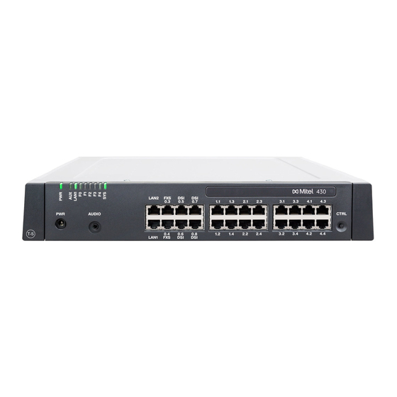
3. 2 Basic system Aastra 415and Aastra 430 are based on the same basic system, they differ in terms of the components fitted to the mainboard, the expansion possibilities and the sys- tem capacities. The basic systems consists of the following components: •... - Page 40 Slot for stackable system modules, type 1 (DSP(X) modules) Slot for stackable system modules, type 2 (not used for the moment) Fig. 7 Mainboard interfaces, display and control elements and front panel Aastra 415/430 as of R3.2 syd-0344/1.6 – R3.2 – 09.2014...
-
Page 41: Power Supply
Circuits for the Call Waiting function DTMF sender DTMF receiver for voice mail or auto attendant DTMF receiver for analogue terminals Dialling tone receiver Busy tone receiver Ring receiver Aastra 415/430 as of R3.2 syd-0344/1.6 – R3.2 – 09.2014... - Page 42 =ym) the VoIP mode parameter is set to G.711. The configured VoIP mode is valid for all the DSP chips of a node. The following also applies to this mode: Aastra 415/430 as of R3.2 syd-0344/1.6 – R3.2 – 09.2014...
-
Page 43: Expansion With Cards And Modules
DSP modules belong to the category of system modules 1 and are stacked to the SM1 slot (see Fig. 7). The different types of modules can be used as a mix. Aastra 415/430 as of R3.2 syd-0344/1.6 – R3.2 – 09.2014... - Page 44 This is carry out by the integrated standard media switch that switches VoIP channels for call connections in the IP network. The Standard Media Switch uses DSP resources for the real-time processing of the call data. VoIP channels are al- Aastra 415/430 as of R3.2 syd-0344/1.6 – R3.2 – 09.2014...
- Page 45 CAS (Channel-associated signaling) is a signalling protocol for PRI network inter- faces used in certain countries (e.g. Brazil). This setting provides the tone sender and receiver for transmitting signalling information. Aastra 415/430 as of R3.2 syd-0344/1.6 – R3.2 – 09.2014...
- Page 46 • Music on hold In normal operation all IP endpoints are registered with • Conversation recording the master, even if they are located on the satellite. • Queue with announcement Aastra 415/430 as of R3.2 syd-0344/1.6 – R3.2 – 09.2014...
- Page 47 Maximum available audio channels on this node. This value depends on the DSP configuration. Reserved for voice mail Number of audio channels on this node that can be used exclusively for voice mail. Aastra 415/430 as of R3.2 syd-0344/1.6 – R3.2 – 09.2014...
- Page 48 The functions which can be allocated to each DSP chip are determined in the DSP configuration ( =ym). The DSP modules provide additional functions as indicated in the following table. All the possible combinations are listed, with the maximum number of voice channels. Aastra 415/430 as of R3.2 syd-0344/1.6 – R3.2 – 09.2014...
- Page 49 Only for VoIP mode G.711 G.711/G.729 Only for VoIP mode G.711 G.711/G.729 1 channel for Aastra 415 2 channels for Aastra 430 Only if Voice mail mode Expanded (G.729 only) Only if Voice mail mode Expanded (G.729 only) Licence(s) required (see also "Licences", page...
-
Page 50: Interface Cards
Interface cards are fitted into slots IC1...IC4 (see Fig. The interfaces are routed to the front panel using the Wiring Adapters (see "Wiring Adapter", page 54). Aastra 415/430 as of R3.2 syd-0344/1.6 – R3.2 – 09.2014... -
Page 51: Trunk Cards
1 BRI-S/T + 1 BRI-S 1)2) ESST • One BRI-T interface configurable to BRI-S, one fixed BRI-S interface • The jumper on this card must always be fitted to position T. Aastra 415/430 as of R3.2 syd-0344/1.6 – R3.2 – 09.2014... -
Page 52: Terminal Cards
2 FXO TIC-2AB 2 FXO EAAB2 Cards with hardware version "-2" only. The ESST-1 card is not operational in Aastra 415/430. Although no longer available, the card is still supported. 3. 3. 2. 2 Terminal cards Terminal cards are used for connecting digital and analogue voice and data termi- nals such as: FXS cards are an exception. -
Page 53: Options Card
T. Although no longer available, the card is still supported. Cards with hardware version "-2" only. The ESST-1 card is not operational in Aastra 415/430. Note On the ESST terminal card the jumper must always be fitted in position T (see Fig. -
Page 54: Wiring Adapter
(Aastra 415) or IC1, 2 and 3 (Aastra 430). Aastra Intelligent Net: A total of 22 ODAB options cards can be used in an AIN with Aastra 430 as Master. However the maximum number of cards per communication server has to be taken into account. An authorized user has the possibility of operating all the door openers, door intercom system and control out- puts in an AIN. -
Page 55: System Capacity
• IP – not IP (internal / external) • IP – IP (internal) • IP – IP via SIP access channels (external) • DECT – not DECT (internal / external) per node Aastra 415/430 as of R3.2 syd-0344/1.6 – R3.2 – 09.2014... - Page 56 Members per trunk group "large" Abbreviated dialling numbers + PISN users 1500 1500 1500 Line keys per key telephone (except Aastra 6700i/6800i) Line keys per key telephone on Aastra 6700i/6800i 2...12 2...12 2...12 Line keys per CDE on Aastra 6700i/6800i...
- Page 57 Up to 20 users are possible with virtual terminals and integrated mobile phones. Up to 100 users are possible with virtual terminals and integrated mobile phones. Only 1 operator console, 1 Aastra 2380ip, 1 BluStar 8000i, 1 Aastra BluStar for PC and 2 DECT- cordless phones are possible for each user.
-
Page 58: Terminals
DHCP clients on the internal DHCP server IP terminals Aastra 2380ip Aastra 5360ip Aastra 5361ip Aastra 5370ip Aastra 5380ip IP operator consoles / IP operator Aastra 5380ip applications Aastra 1560ip Aastra 415/430 as of R3.2 syd-0344/1.6 – R3.2 – 09.2014... - Page 59 Operation on 2 DSI interfaces in each case Maximum of 2 simultaneous call connections. Transmission with the T.38 protocol is recommended for Fax over IP. The corresponding DSP resources need to be allocated. Aastra 415/430 as of R3.2 syd-0344/1.6 – R3.2 – 09.2014...
-
Page 60: Terminal And Network Interfaces
EID number. Detailed instructions about this can be found in the WebAdmin help on the Licences ( =q9) view. If you receive a voucher instead of a licence code, log on to Aastra Connect with your partner login. Aastra 415/430 as of R3.2... - Page 61 In an AIN a valid Software Release licence is required at all the nodes in order to update to a new software release for the communication server. The licence (as well as the temporary/definite activation tool) is not available in each sales channel. Aastra 415/430 as of R3.2 syd-0344/1.6 – R3.2 – 09.2014...
- Page 62 Aastra BluStar 8000i Desktop Media Phone, for cordless terminals logged on via Aastra SIP DECT or Aastra SIP WLAN base stations, and for SIP users for the TWP application (Telephony Web Portal), one licence is required per terminal or user.
- Page 63 In the event of failure of the primary communication server or an interruption in the IP connection to the primary communication server, SIP phones in the Aastra 6700i/6800i series can automatically register on a backup communica- tion server. On the backup communication server one licence is required per phone.
- Page 64 The feature is used mainly in call centres. One licence is required per system /AIN. • Analogue Modem This licence allows remote maintenance of an Aastra 415/430 using an analogue modem. For this the Modem function must be allocated to the mainboard DSP.
- Page 65 • G.729 Codec This licence allows the use of a G.729 codec for the voice channel of Aastra SIP phones, IP system phones and SIP network interfaces (also for SIP networking). The licence is also needed for the voice compression of voice mail audio data, if the Enterprise voice mail system in expanded mode.
- Page 66 These licences are used to implement a private leased-line network with QSIG by enabling a specific number of simultaneously outgoing QSIG channels. Two li- cence levels are available (see Tab. 31). Aastra 415/430 as of R3.2 syd-0344/1.6 – R3.2 – 09.2014...
- Page 67 Expansion Stages and System Capacity • Basic Aastra Intelligent Net This licence allows an Aastra Intelligent Net to be set up and operated with one Master and one satellite. Note: This licence is not available for Aastra 415. • Aastra Intelligent Net Satellites An upgrade licence for each additional satellite is required to integrate more than one satellite in an Aastra Intelligent Net.
- Page 68 Redkey). ATASpro Interface licence can also be used to determine the position of users of Aastra DECT cordless phones, which can be visualized with the appropriate applications. Note: If you use the Open Interfaces Platform, OIP takes the licences from the communication server.
- Page 69 • Voice mail functions are out of service (no call routing to voice mail). • The announcement service is out of service. Restrictions in an Aastra Intelligent Net In an AIN, the satellites carry out a restart every four hours.
- Page 70 ✓ Aastra 2380ip Soft- Number of registered per licence 1 addi- In the AIN, phones Aastra 2380ip IP soft- tional IP softphone only on the phones Master; otherwise per node. Aastra 415/430 as of R3.2 syd-0344/1.6 – R3.2 – 09.2014...
- Page 71 Dual Homing Number of registered per licence 1, 20 or 50 Always on – Aastra 6700i/6800i SIP additional phones the backup phones on a backup communi- communication server cation server Aastra 415/430 as of R3.2 syd-0344/1.6 – R3.2 – 09.2014...
- Page 72 ' Master; otherwise per node. Features Secure VoIP Encrypted VoIP connec- Non- Encrypted transmis- per node – – tions using SRTP and TLS. encrypte sion d trans- mission Aastra 415/430 as of R3.2 syd-0344/1.6 – R3.2 – 09.2014...
- Page 73 Lync-specific options per node. and features. Private networking ✓ ✓ QSIG Networking QSIG channels per licence 4 or n QSIG per node Channels channels (n limited by the system capacity) Aastra 415/430 as of R3.2 syd-0344/1.6 – R3.2 – 09.2014...
- Page 74 ✓ ✓ Aastra OpenCount Additional licence: Offers unavaila- enabled In the AIN, Functional Upgrade extra functions such as only on the to Comfort PIN telephony. Master; otherwise per node. Aastra 415/430 as of R3.2 syd-0344/1.6 – R3.2 – 09.2014...
- Page 75 ✓ CSTA Sessions Number of monitored 1, 20, 50 or 100 CSTA In the AIN, terminals via the CSTA sessions per licence only on the protocol. Master; otherwise per node. Aastra 415/430 as of R3.2 syd-0344/1.6 – R3.2 – 09.2014...
-
Page 76: Power Supply Capacity
The 40 VDC power supply required for the connected terminals is rated for the power requirements of a typical system configuration. Tab. 32 Power output of the 40 VDC power supply Aastra 415 Aastra 430 Available power output 24 Watt 24 Watt Aastra 415/430 as of R3.2 syd-0344/1.6 – R3.2 – 09.2014... - Page 77 – SB-4+ radio unit: Active call connection on 2 channels – SB-8 radio unit: Active call connection on 4 channels – Background lighting Aastra 5380: 30% active – LEDs on terminals and expansion key modules: 20% active. – Wire diameter: 0.5 mm –...
-
Page 78: Power Supply Per Terminal Interface
The value applies to phones with hardware version "-2". The value for phones with hardware version "-1" is 60 mW lower. The value depends greatly on the terminal type. With the planning application Aastra Plan the power supply available for terminals is checked automatically. Overload shutdown If the rated power is exceeded the power supply is disconnected. -
Page 79: Installation
Installation Installation This Chapter tells you how Aastra 415/430 can be installed and the conditions to be observed. It also includes the mounting into a 19” rack, the correct way to connect the earthing, and the power supply. Other topics described in this Chapter comprise fitting with system modules, interface cards and the rele- vant Wiring Adapters. -
Page 80: Fitting The Communication Server
Installation 4. 2 Fitting the communication server The Aastra 415/430 communication server is suitable for both wall and desktop in- stallation as well as for mounting in a 19” rack. Different mounting sets are available in each case. 4. 2. 1... -
Page 81: Aastra 415 Rack-Mounting Set
An event message is generated if the heat dissipation is insufficient. Appropriate measures must be taken immediately to improve the heat dissipation, e.g. by providing the required clearances, lowering the ambi- ent temperature or installing the fan from the rack-mounting set (Aastra 430 only). Tab. 34... -
Page 82: Safety Regulations
The two diagrams below illustrate the two wall-mounting possibilities. Aastra 415/430 as of R3.2 syd-0344/1.6 – R3.2 – 09.2014... - Page 83 All dimensions in mm Fig. 12 Minimum distances for wall mounting (front panel facing to the right) All dimensions in mm Fig. 13 Minimum distances for wall mounting (front panel facing downwards) Aastra 415/430 as of R3.2 syd-0344/1.6 – R3.2 – 09.2014...
-
Page 84: Drilling Plan
The communication server is secured with a third screw to prevent it from being dislodged accidentally (position C). All dimensions in mm Fig. 14 Drilling plan for Aastra 415/430 wall mounting Aastra 415/430 as of R3.2 syd-0344/1.6 – R3.2 – 09.2014... -
Page 85: Drilling Template
To do so it is best to detach the part of the inner packaging box that contains the drill holes. Note: The holes on the cardboard box are not labelled. Fig. 15 Drilling template Aastra 415/430 as of R3.2 syd-0344/1.6 – R3.2 – 09.2014... -
Page 86: Wall-Mounting Procedure
The holes in the housing cover are spaced in such a way that the snap- on tag can be secured both lengthways and crossways. 12.Reconnect the communication server to the power supply. Aastra 415/430 as of R3.2 syd-0344/1.6 – R3.2 – 09.2014... -
Page 87: Desktop Installation
• The space on the left and right between the communication server and the pan- els of the 19” rack is for heat dissipation and must remain clear. • The installation of a fan is mandatory whenever an Aastra 430 is rack-mounted; the fan is included in the Aastra 430 rack-mounting kit. -
Page 88: Rack-Mounting Procedure
Placing two communication servers above each other inside a 19” rack 4. 2. 7. 1 Rack-mounting procedure Materials required: • Aastra 415 and Aastra 430 rack-mounting kit • Screw set for wall/desktop installation • Screwdriver To rack-mount an Aastra 415/430 proceed as follows: 1. -
Page 89: Installing The Fan
4. 2. 7. 2 Installing the fan Materials required: • Fan from the Aastra 430 rack-mounting kit • 2 screws from the Aastra 430 rack-mounting set • Screwdriver To install the fan proceed as follows: 1. Shut down the communication server (see "Shutdown Mode", page... -
Page 90: Installing The Cable Cover
4. 2. 7. 3 Installing the cable cover Materials required: • Cable cover set for Aastra 415/430 • Screwdriver To install the cable cover proceed as follows: 1. Pull off the screw covers on the left and right of the front panel. -
Page 91: Earthing And Protecting The Communication Server
Operation on an IT current distribution system: The communication server can be operated on an IT power distribution system as per EN/IEC 60950 with voltages of up to 230 VAC. Aastra 415/430 as of R3.2 syd-0344/1.6 – R3.2 – 09.2014... -
Page 92: Connecting The Earthing Wire
The earthing wire is secured by a screw, spring washer and serrated lock washer, which are included in the screw set Aastra 415/430. The serrated lock washer must rest against the metal housing of the communication server. - Page 93 (main) distribution frame. The cables should be kept as short as possible and laid out in parallel. Aastra 415/430 as of R3.2 syd-0344/1.6 – R3.2 – 09.2014...
-
Page 94: Connecting The Cable Screening
Connect the cable screens to one another at the splitting point only. Observe the tree structure principle to prevent earth loops. Socket-outlets (Main) distribution board Communica- tion server No earth loops Fig. 21 Tree structure principle Aastra 415/430 as of R3.2 syd-0344/1.6 – R3.2 – 09.2014... -
Page 95: Powering The Communication Server
• Only ever use the supplied power supply unit. Mains power 1.5 m 1.8 m Power supply Fig. 22 Powering the communication server from the mains Aastra 415/430 as of R3.2 syd-0344/1.6 – R3.2 – 09.2014... -
Page 96: Uninterruptible Power Supply (Ups)
247. 4. 5 Equipping the Basic System For an individual expansion the Aastra 415/430 basic system can be equipped with interface cards, the appropriate wiring adapters and system modules. An overview can be found in the Chapter "Expansion Stages and System Capacity", page 4. - Page 97 Fitting an interface card Notes – The ODAB options card must be fitted to slot IC2 (Aastra 415) or slot IC4 (Aastra 430) if it is to be used for connecting a door intercom (see "Equipment on the ODAB options card", page 138).
-
Page 98: Wiring Adapter
Wiring adapters are used to route the interfaces of the interface cards to the RJ45 sockets on the front panel and are fitted to slots WA1…WA4. The WA0 slot is never equipped. Slots WA3 and WA4 are to be found only on the Aastra 430 (see also Fig. -
Page 99: Dsp Module
6. Secure the module with the fastening screw. 7. Fit the housing cover. 8. Reconnect the communication server to the power supply. Aastra 415/430 as of R3.2 syd-0344/1.6 – R3.2 – 09.2014... -
Page 100: Component Mounting Rules
IC2 (Aastra 415) or slot IC4 (Aastra 430). – If the ODAB options card is used to control switch group positions and exter- nal devices, it must be fitted to slot IC1 (Aastra 415) or slot IC1, 2 or 3 (Aastra 430). -
Page 101: Connecting The Communication Server
There are two possibilities for connecting the communication server indirectly to the telephone network and terminal-side cabling: • Connection via main distribution board • Connection to a universal building cable installation (UBC) Aastra 415/430 as of R3.2 syd-0344/1.6 – R3.2 – 09.2014... -
Page 102: Connection Via Main Distribution Board
(see also "Connection of a door intercom (TFE)", page 138). Use standard commercial connecting cables not just for the PRI and Ethernet interfaces but also for connecting the BRI-T interfaces. Aastra 415/430 as of R3.2 syd-0344/1.6 – R3.2 – 09.2014... - Page 103 – turquoise – violet – – blue – turquoise – violet – – orange – turquoise – violet – View A View B Fig. 27 Pin numbering, RJ45 connector Aastra 415/430 as of R3.2 syd-0344/1.6 – R3.2 – 09.2014...
-
Page 104: Connection To A Universal Building Cable Installation (Ubc)
Connecting to a UBC via a (main) distribution board (example) Communica- tion server User Patch panel Phone User side Phone Exchange side Public exchange Fig. 29 Connecting to a UBC via wiring centre (example) Aastra 415/430 as of R3.2 syd-0344/1.6 – R3.2 – 09.2014... -
Page 105: Cabling Interfaces
A port address is always of the type x.y. x is the number of the card slot, and y, the port number. The slot numbering begins with 0 (=mainboard) and ends with 2 (for Aastra 415) or 4 (for Aastra 430). -
Page 106: Network Interfaces
Basic rate interface BRI-T With the appropriate interface cards and Wiring Adapters, BRI network interfaces can be made available at RJ45 sockets 1.x...4.x (for Aastra 415 1.x and 2.x only). The possible RJ45 sockets are highlighted in colour in the figure below. - Page 107 Basic access in the private leased-line network BRI-T BRI-S Copper line extern PINX 1 PINX 2 max. 1,000 m Fig. 33 BRI-S basic rate interface , networked with copper line external Aastra 415/430 as of R3.2 syd-0344/1.6 – R3.2 – 09.2014...
-
Page 108: Primary Rate Interface Pri
With the appropriate interface cards and Wiring Adapters, PRI network interfaces can be made available at RJ45 sockets 1.1, 2.1, 3.1 and 4.1 (Aastra 415 only 1.1, 2.1). For test purposes the PRI interface is also routed in parallel to ports x.2. The possi- ble RJ45 sockets are highlighted in colour in the figure below. - Page 109 < 6 dB/km (100 kHz), < 26 dB/km (1 MHz) Near/crosstalk attenuation > 54 dB/100 m (1 kHz to 1 MHz) PRI primary rate interface, network-side Mains power Exchange Communication server Fig. 36 PRI primary rate interface on NT1 Aastra 415/430 as of R3.2 syd-0344/1.6 – R3.2 – 09.2014...
- Page 110 Cabling for primary rate access PRI, networked with copper line RJ45 PRI PINX 1 sig- Cable cores PRI PINX 2 RJ45 Crossed patch cable signal — — — — — — — — Aastra 415/430 as of R3.2 syd-0344/1.6 – R3.2 – 09.2014...
- Page 111 — — — — — — Leased-line or dial-up PINX 1 PINX 2 connection Mains power Mains power Fig. 39 Primary rate access PRI, networked with leased-line or dial-up connection Aastra 415/430 as of R3.2 syd-0344/1.6 – R3.2 – 09.2014...
-
Page 112: Fxo Network Interfaces
With the appropriate interface cards and Wiring Adapters, FXO network interfaces can be made available at RJ45 sockets 1.x...4.x (for Aastra 415 only 1.x and 2.x) The possible RJ45 sockets are highlighted in colour in the figure below. The maximum number of interfaces per communication server has to be taken into account (see Tab. - Page 113 Cable requirements for FXO network interface Core pairs cores 1 2 Stranded not required Wire diameter, core 0.4 … 0.8 mm Screening not required max. 2 250 Resistance Aastra 415/430 as of R3.2 syd-0344/1.6 – R3.2 – 09.2014...
-
Page 114: Terminal Interfaces
4. 7. 3. 1 DSI terminal interfaces The DSI terminal interfaces of the mainboard (for Aastra 415 only 0.5 and 0.6) are permanently routed to the front panel and labelled accordingly. With the appropri- ate interface cards and Wiring Adapters, additional DSI terminal interfaces can also be made available at the RJ45 sockets 1.x...4.x (with Aastra 415 only 1.x and 2.x). - Page 115 Installation DSI bus configuration Depending on the line length, 1 or 2 system phones of the Aastra 5300 series can be connected on each DSI-AD2 interface. The following requirements apply with regard to the bus length to ensure that the maximum permissible signal delay is not exceeded: Tab.
- Page 116 The value can increase to approx. 600 mW if the power available at the DSI-AD2 bus allows it. An Aastra M535 always requires a power supply unit The value applies to radio units with hardware version "-2". The value for hardware version "-1" is 300 mW lower.
- Page 117 DSI-AD2 bus is not the same in every case: Power available A: • Applies to all the system phones of the Aastra 5300 series and the Office series. • Applies to the SB-4+/SB-8 DECT radio units with hardware version "-1".
- Page 118 Notes – If another system phone is operated on the DSI-AD2 bus in addition to an Aastra 5361, Aastra 5370 or Aastra 5380, at least one phone must be powered by a local power supply unit. – An Aastra 5370 or Aastra 5380 with an Aastra M535 expansion key module always requires a power supply unit.
- Page 119 – Depending on the power available based on the line length on the DSI-AD2 bus the ringing and hands-free volume decreases accord- ingly. – The backlighting of the Aastra 5380 display is brighter if the phone is powered by a power supply unit. Rating examples...
- Page 120 (CH: Applies also to cable type G51) Installation rules • If an Aastra DECT radio unit is used, do not connect any other system phone to the same DSI bus. • Do not use any terminating resistors at the bus extremity.
-
Page 121: Bri-S Terminal Interfaces
BRI-S terminal interfaces With the appropriate interface cards and Wiring Adapters, BRI-S terminal interfaces can be made available at RJ45 sockets 1.x...4.x (for Aastra 415 only 1.x and 2.x). The possible RJ45 sockets are highlighted in colour in the figure below. - Page 122 The maximum number of terminals per S bus depends on the power requirements of the terminals (see "Restrictions", page 123). 8. Connection point Communica- 2 x 100 Ω tion server max. 150 m Fig. 46 S bus, short Aastra 415/430 as of R3.2 syd-0344/1.6 – R3.2 – 09.2014...
- Page 123 Tab. 56 Power balance on the S bus Power available [W] S bus short S bus, long These values are based on a wire diameter of 0.5 mm. Aastra 415/430 as of R3.2 syd-0344/1.6 – R3.2 – 09.2014...
- Page 124 Fit resistors at bus extremity only Fig. 50 RJ45 connection, single socket RJ45, double Front view of RJ45 Connect housing screens Ω 2x100 Fit resistors at bus extremity only Fig. 51 RJ45 connection, double socket Aastra 415/430 as of R3.2 syd-0344/1.6 – R3.2 – 09.2014...
-
Page 125: Fxs Terminal Interfaces
With the appropriate interface cards and Wiring Adapters, additional FXS terminal interfaces can also be made available at the RJ45 sockets 1.x...4.x (with Aastra 415 only 1.x and 2.x). The possible RJ45 sockets are highlighted in colour in the figure below. - Page 126 Tab. 58 Connection of FXS terminal interfaces Communication server Cable cores Connection socket Analogue Analogue Socket Socket signal signal – – – – – – – – – – – – Aastra 415/430 as of R3.2 syd-0344/1.6 – R3.2 – 09.2014...
- Page 127 • Radio units for cordless phones • Group 3 fax • Answering machines • Modem Transmission with the T.38 protocol is recommended for Fax over IP. The corresponding DSP resources need to be allocated. Aastra 415/430 as of R3.2 syd-0344/1.6 – R3.2 – 09.2014...
- Page 128 In this mode 2-wire door intercoms with DTMF control functions can be connected. The no-load voltage in this mode is 24 VDC. The loop current is limited to 25 mA. FXS interface Fig. 54 Connection for FXS mode: 2-wire door Aastra 415/430 as of R3.2 syd-0344/1.6 – R3.2 – 09.2014...
- Page 129 Besides the control outputs on FXS interfaces control outputs on ODAB cards can also be used to control external devices and equipment (see "Equipment on the ODAB options card", page 138). Aastra 415/430 as of R3.2 syd-0344/1.6 – R3.2 – 09.2014...
- Page 130 • The same switch group can only be switched by the 2 assigned control inputs. • Control of the switch groups using the control inputs takes priority over control using function codes. Aastra 415/430 as of R3.2 syd-0344/1.6 – R3.2 – 09.2014...
-
Page 131: Emergency Fan-Out-Panel (Efop)
If for example ports are switched off due to overloading, the corre- sponding exchange lines switch over automatically and directly to the analogue phones. Available as of R2.1 SP1 Aastra 415/430 as of R3.2 syd-0344/1.6 – R3.2 – 09.2014... - Page 132 115/230 VAC A C / D C C o n tro l V oltage detec tion 1 … 8 1 … 8 Communication server Fig. 59 Block diagram, EFOP fan-out-panel Aastra 415/430 as of R3.2 syd-0344/1.6 – R3.2 – 09.2014...
- Page 133 FXS line and the exchange line prior to the emer- gency operation. – In emergency operation the emergency phone is connected directly with the analogue exchange line so no exchange access prefix has to be dialled. Aastra 415/430 as of R3.2 syd-0344/1.6 – R3.2 – 09.2014...
- Page 134 The internal wiring of the 3 connectors right is shown in the table below. The wir- ing is shown for sockets 1 - 4. Sockets 5 - 8 are wired accordingly. Aastra 415/430 as of R3.2 syd-0344/1.6 – R3.2 – 09.2014...
- Page 135 EFOP fan-out-panel Socket Signal Signal Socket – – – – – – – – – – – – – – – – – – – – – – – – Aastra 415/430 as of R3.2 syd-0344/1.6 – R3.2 – 09.2014...
- Page 136 (see Fig. 61). Warning Because analogue trunk lines are to be routed via the fan-out panel EFOP, for safety reasons the fan-out panel must be connected to the protective earth. Aastra 415/430 as of R3.2 syd-0344/1.6 – R3.2 – 09.2014...
- Page 137 EFOP fan-out-panel to the mains power. This prevents an unwanted switchover in the event of a mains failure on the EFOP fan-out-panel only. Aastra 415/430 as of R3.2 syd-0344/1.6 – R3.2 – 09.2014...
-
Page 138: Equipment On The Odab Options Card
Interfaces of the ODAB options card 4. 7. 5. 1 Connection of a door intercom (TFE) If the options card is fitted to slot IC2 (Aastra 415) or slot IC4 (Aastra 430), an ana- logue terminal interface is available for connecting a door intercom. Note: This analogue terminal interface cannot be used for other purposes as the software does not support it. - Page 139 Fig. 63 Jumper configuration for connecting a door intercom Note If the options card is fitted to slot IC2 (Aastra 415) or slot IC4 (Aastra 430), the jumpers of Ports 1, 2 and 3 must be fitted as shown in Fig.
- Page 140 • The door release is actuated via the TO contact output. Warning – The bell key switch does not require an external power supply, but must have a floating connection. Aastra 415/430 as of R3.2 syd-0344/1.6 – R3.2 – 09.2014...
-
Page 141: Control Outputs And Control Inputs
4. 7. 5. 2 Control outputs and control inputs If the options card is fitted to slot IC1 (Aastra 415) or slot IC1, 2 or 3 (Aastra 430), the analogue terminal interface cannot be used. However two control inputs can be used for switching a switch group and two control outputs for controlling external devices or equipment. - Page 142 Installation Tab. 68 Connection in slot IC1 (Aastra 415) or slot IC1, 2 or 3 (Aastra 430) Communication Communication RJ45 RJ45 server server Socket X1 Signal Socket X3 Signal – – – – O1-1 – O2-1 – O2-2 – O1-2 –...
-
Page 143: Audio Interface
• to play music or an announcement for the announcement service (announce- ment prior to answering), voice mail greetings or for "Music on hold" and then to store it as a wave file. Aastra 415/430 as of R3.2 syd-0344/1.6 – R3.2 – 09.2014... -
Page 144: Ethernet Interfaces
4. 7. 7 Ethernet interfaces The Aastra 415/430 communication servers have a 10/100BaseT 2-port LAN switch. The Ethernet interfaces are permanently routed to the front panel and labelled ac- cordingly. The RJ45 sockets are highlighted in colour in the figure below. - Page 145 DHCP server and to enter its host name on the DNS server. If logon is successful the communication server is accessible via the host name. Aastra 415/430 as of R3.2 syd-0344/1.6 – R3.2 – 09.2014...
- Page 146 Wire diameter, core 0.4...0.6 mm Screening Category Cat. 5 minimum See also: For more information about the Ethernet interface on the application card, see the CPU2-S application card installation manual. Aastra 415/430 as of R3.2 syd-0344/1.6 – R3.2 – 09.2014...
-
Page 147: Installing, Powering And Connecting Terminals
– A terminal has been created at the connected port, but the address selection switch is incorrectly set. – No terminal has yet been created at the connected port. Aastra 415/430 as of R3.2 syd-0344/1.6 – R3.2 – 09.2014... -
Page 148: Aastra 5360/5361/5370/5380
These IP system phones can be both desktop-mounted and wall-mounted. Mounting the phone The following points are described in detail in the User’s Guides for Aastra 5360/ 5361/5370/5380: • Set-up as a desk phone (choice of two different set-up angles) •... - Page 149 To prevent any damage to the phone, always disconnect the phone from the power supply first before connecting a headset to DHSG standard. Mounting the Bluetooth module The Aastra 5380 can also be equipped with a Bluetooth module as an option. To in- stall (see Fig. 68), proceed as follows: Fig.
-
Page 150: Office 25, Office 35, And Office 45/45Pro
(see ➃). Powering the phone The Aastra 5360, Aastra 5361 Aastra 5370 and Aastra 5380 system phones are nor- mally powered via the DSI bus. However there are several reasons that require pow- ering with a plug-in power supply: •... - Page 151 Connecting the expansion key module or the alphanumerical keyboard The connection of the expansion key modules and the alphanumerical keyboard to Office 35 and Office 45 is described in the relevant operating instructions. Aastra 415/430 as of R3.2 syd-0344/1.6 – R3.2 – 09.2014...
- Page 152 Installation Fig. 69 Wall mounting of Office 25 and Office 35 Aastra 415/430 as of R3.2 syd-0344/1.6 – R3.2 – 09.2014...
-
Page 153: Office 10
4. Label terminal. Fig. 70 Set the DSI bus address Note: Make sure the TSD (address switch) is pushed in as far as the stop or the switchover will not function correctly. Aastra 415/430 as of R3.2 syd-0344/1.6 – R3.2 – 09.2014... -
Page 154: Dect Radio Units And Cordless Phones
• Minimum distance between charging bays with cordless phones on-hook for fault-free operation: 0.2 m. Ambient conditions • When installing: Ensure convection (space for ventilation). • Avoid excessive dust. • Avoid exposure to chemicals. Aastra 415/430 as of R3.2 syd-0344/1.6 – R3.2 – 09.2014... -
Page 155: Installing The Radio Units
Office 135 charging bay. ø screw : 4 mm Mounting bracket All dimensions in mm Fig. 71 Dimensional drawing for wall-mounting the mounting bracket Aastra 415/430 as of R3.2 syd-0344/1.6 – R3.2 – 09.2014... - Page 156 Installation distances Connecting the radio unit 230 VAC (optional) DSI interface Socket 1 Socket 2 Sockets, external antennas ( SB-8ANT only) Fig. 73 Underside of the radio units with connection points Aastra 415/430 as of R3.2 syd-0344/1.6 – R3.2 – 09.2014...
-
Page 157: Analogue Phones Aastra 6710A, Aastra 6730A
As the DECT systems of the individual nodes in an AIN do not run syn- chronously, the two DSI interfaces of an SB-8 / SB-8ANT must always be connected to the same node. Tab. 78 Operating state display on Aastra DECT radio units LED flashing (two LEDs on the SB-8) Information green... - Page 158 No symbol (Any switch setting) The red MWI LED under the notification key can only be controlled with the Aastra 470 communication server and the notification type Polarity reversal. Set the switch on the underside of the phone to the symbol "−". This applies to a straight connecting cable (provided with the phone).
-
Page 159: Ip System Phones
Update key configuration on phone. To load the key configuration on all connected Aastra 6700a series phones, click Update key configuration for all Aastra 6700a phones. To load the key configuration stored in the WebAdmin from the connected phone, dial the function code *#53. -
Page 160: Oip Applications
"Open Interfaces Platform". 4. 8. 6 Aastra SIP and standard SIP phones The registration of SIP system phones of the Aastra 6700i/6800i series, other Aastra SIP terminals and SIP terminals by other manufacturers as internal users is de- scribed in WebAdmin. -
Page 161: Configuration
400 series communication servers. It offers a simple, user-friendly interface and an online help, and with its different authorization levels it is aimed at different user groups: Fig. 74 WebAdmin Configuration Tool Aastra 415/430 as of R3.2 syd-0344/1.6 – R3.2 – 09.2014... - Page 162 The Hospitality Administrator features all the views required to set up the Aastra Hospitality Manager and the reception menu of the Aastra 5380/5380ip and spec- ify its default settings. A link can also be used to start the Aastra Hospitality Man- ager (see "Aastra Hospitality Manager", page...
-
Page 163: Integrated And Auxiliary Applications
Integrated and auxiliary applications Aastra Hospitality Manager The Aastra Hospitality Manager is a web-based application for receptionists in the hospitality sector. It provides a clear, at-a-glance list view or floor-by-floor view of the rooms and features functions such as check-in, check-out, notification, wake- up call, retrieval of call charges, maintenance list, etc. - Page 164 • Windows user name + PIN • Windows user name + password The standard PIN "0000" is accepted, but must be changed during first login. You can choose any 2 to 10-digit number combination. Aastra 415/430 as of R3.2 syd-0344/1.6 – R3.2 – 09.2014...
- Page 165 WebAdmin, Hospitality Manager and Self Service Portal via Aastra 400 FTP server onto your PC and upload them after- wards to the communication server with WebAdmin. Thus, an update or an upload of new languages is possible without an internet connection of the communica- tion server.
- Page 166 If the integrated voice mail system is operated in ex- panded mode (Aastra 415/430 only), all the audio data must be available in com- pressed G.729 format. To be able to continue using existing, uncompressed greet- ings in G.711 format, you need to compress them first.
-
Page 167: Access Types
165) the communication server (and other Aastra 400 series communication servers on the same subnet) is searched and displayed. It is advisable to directly deactivate the normally activated communication server DHCP via System Search and to manually enter a static IP address, the subnet mask and IP gateway. -
Page 168: User Access Control
To prevent unauthorised access to the communication server, it is neces- sary to modify the default password during first access. For password selection and input, see "Password syntax", page 170. Aastra 415/430 as of R3.2 syd-0344/1.6 – R3.2 – 09.2014... -
Page 169: Authorization Profiles
Configuration Other predefined user accounts The predefined user account AMCC is meant for operating an Aastra Mobile Client Controller. The two predefined user accounts blustar bucs are meant for BluStar terminals and for a BluStar server. You can see the predefined user accounts in the User account =a7) view. -
Page 170: Passwords
The same applies to users whose ac- counts have been newly created. Users without the administration right User access control can only change their own password. Aastra 415/430 as of R3.2 syd-0344/1.6 – R3.2 – 09.2014... -
Page 171: Access With Incorrect Password
Automatic exit from the configuration Access to the configuration is interrupted if no changes are made to a parameter value or the navigation system is not used during a specific timeout. Aastra 415/430 as of R3.2 syd-0344/1.6 – R3.2 – 09.2014... -
Page 172: Access Log
Remote maintenance access can be enabled in three ways: • Using function codes (see page 173) • With WebAdmin • With the System Assistant on the Office 45 It can be revoked again automatically or manually. Aastra 415/430 as of R3.2 syd-0344/1.6 – R3.2 – 09.2014... -
Page 173: Function Code For Remote Maintenance Access
Remote maintenance access can also be enabled or barred in WebAdmin or with the System Assistant function on the Office 45, if the relevant authorization has been given. Aastra 415/430 as of R3.2 syd-0344/1.6 – R3.2 – 09.2014... -
Page 174: Function Keys For Remote Maintenance Access
The relevant LED goes off as soon as remote maintenance access is denied again, either automatically or manually, using the function code, WebAdmin or the sys- tem assistant on Office 45. Aastra 415/430 as of R3.2 syd-0344/1.6 – R3.2 – 09.2014... -
Page 175: Configuring
The configuration steps are based on the information determined during the plan- ning and, where applicable, the installation. Whenever possible, use the planning and ordering software Aastra Plan, to set up your communication system. Aastra Plan can be operated online after logging in at Aastra Connect http://connect.aastra.com. -
Page 176: Configuration Notes
CPU2-S application card. 5. 6 Configuration Notes The sections below contain information that may be useful before, during or after a configuration. The application card CPU2 is no longer available. Aastra 415/430 as of R3.2 syd-0344/1.6 – R3.2 – 09.2014... -
Page 177: Licences
In this view language files can be manually or automati- cally loaded for Aastra 6700i and Aastra 6800i SIP phones via FTP server. Moreo- ver, you can manually or automatically load the languages for the WebAdmin, Hospitality Manager and Self Service Portal user interface and online help, as well as an external numbering plan for the SIP connection via the FTP server. -
Page 178: System Reset
A first start has the effect of resetting the communication server from scratch. The system-specific data such as the system ID, system type, sales channel, licence code, software generation and IP address of the system are preserved. Aastra 415/430 as of R3.2 syd-0344/1.6 – R3.2 – 09.2014... -
Page 179: Data Backup
=um) view, where you can also test them. Moreover, in this view you can see the available backups of the auto-backup func- tion; you can restore or delete them and even create and restore manual backups. Aastra 415/430 as of R3.2 syd-0344/1.6 – R3.2 – 09.2014... -
Page 180: Auto Backup
• The e-mail distribution service sends a copy of each auto backup created to a preconfigured e-mail address. • The FTP distribution service stores a copy of each auto-backup created on an FTP server. Aastra 415/430 as of R3.2 syd-0344/1.6 – R3.2 – 09.2014... -
Page 181: Manual Backup
See also: The procedure for creating and restoring a backup is described in detail in the WebAdmin help on the Data backup ( =um) view. Aastra 415/430 as of R3.2 syd-0344/1.6 – R3.2 – 09.2014... -
Page 182: Importing And Exporting User Data
This action deletes all previously configured user data and all user associated settings such as DDI numbers, CDE targets, user group entries, assigned phones, configured keys, etc. Aastra 415/430 as of R3.2 syd-0344/1.6 – R3.2 – 09.2014... -
Page 183: Operation And Maintenance
(system ID, system type, sales channel, licence code, generation, DECT iden- tification numbers, IP address of the configuration server). The contents of the memory are retained even when there is no power supply. Aastra 415/430 as of R3.2 syd-0344/1.6 – R3.2 – 09.2014... -
Page 184: System Software
EIM card Range of the Flash chips Fig. 79 Memories on the mainboard Aastra 415/430 6. 1. 1. 1 System software The communication server's entire system software package is stored in com- pressed form in the Flash memory. The RAM components comprise the main memory for program data. When the PBX starts up, the communication server software on the serial Flash memory is decom- pressed, loaded into the main memory and started. -
Page 185: Boot Software
Operation and Maintenance guages for the user interface and online help, language files for Aastra 6700i and Aastra 6800i-series SIP phones as well as an external numbering plan for SIP con- nection. Moreover, with the file browser you have the possibility to view, upload, replace or delete the folders and files in the file system. -
Page 186: Update Software
1. Access the configuration menu Settings. 2. Long-click on the * key Information can be retrieved on Aastra 6800i/Aastra 6700i SIP phones as well as on Aastra 610d/Aastra 600d DECT phones via the menu. Depending on the phone, additional information is displayed. - Page 187 1. Set the communication server to boot mode using the control key (see "Boot Mode", page 210). 2. Start System Search and select Emergency Upload. 3. Enter the communication server IP address. Aastra 415/430 as of R3.2 syd-0344/1.6 – R3.2 – 09.2014...
-
Page 188: Firmware For Corded System Phones
The flash memory contains the boot software and the application software. DSI phones also have an area with the interface software. The firmware for the phones Office 35, Office 45, Aastra 5370, Aastra 5380 as well as for all Aastra 5300ip series IP phones is contained in the communication server's system software. -
Page 189: Firmware System Aastra 400 Dect
There is only one firmware for the cordless Aastra 600c/d series phones. It is in- cluded in the communication server's software package and stored in the file sys- tem of the communication server. -
Page 190: Firmware System Aastra Sip-Dect
Aastra SIP-DECT® system from the one in an Aastra 400 DECT system. The firmware for the RFP radio units and for the Aastra 600d cordless phones is preferably located on a firmware server. Automatic firmware update is then possi- ble. -
Page 191: Cpu2/Cpu2-S Applications Card
Disconnect communication server power supply Shut down the communication server (see "Shutdown Mode", page 211) and dis- connect it from the power supply. The application card CPU2 is no longer available. Aastra 415/430 as of R3.2 syd-0344/1.6 – R3.2 – 09.2014... -
Page 192: Licenses And Eim Card
The EIM card must be replaced in the following cases: • A licence is transferred to another communication server • The mainboard is defective • The EIM card is defective Aastra 415/430 as of R3.2 syd-0344/1.6 – R3.2 – 09.2014... -
Page 193: Interface Cards
A card is replaced by the same card type with the same number of ports. Procedure: Warning Be sure to observe the "Safety regulations", page 1. Carry out preparations (see "Preparations", page 191). 2. Remove the housing cover. Aastra 415/430 as of R3.2 syd-0344/1.6 – R3.2 – 09.2014... -
Page 194: New Card With Fewer Ports
However, this is pos- sible only if the configuration data of the original card was not already deleted beforehand. Aastra 415/430 as of R3.2 syd-0344/1.6 – R3.2 – 09.2014... -
Page 195: New Card With More Ports
The configuration data at the old slot location is now deleted. Note: Not all cards can be equipped on all slots (see "Component mounting rules", page 100). Aastra 415/430 as of R3.2 syd-0344/1.6 – R3.2 – 09.2014... -
Page 196: System Modules
4. Press the new module downward evenly on both connectors to the stop. 5. Secure the module with the fastening screw. 6. Fit the housing cover. 7. Reconnect the system to the power supply. Aastra 415/430 as of R3.2 syd-0344/1.6 – R3.2 – 09.2014... -
Page 197: System Cards
EIM card is pointing towards the edge of the main- board (see Fig. 80). 5. Fit the housing cover. 6. Reconnect the communication server to the power supply. Fig. 80 EIM card Aastra 415/430 as of R3.2 syd-0344/1.6 – R3.2 – 09.2014... -
Page 198: Mainboard
8. Carry out a first start of the system (see "First start of the communication server", page 178) and upload the configuration data back on to the communication server. Aastra 415/430 as of R3.2 syd-0344/1.6 – R3.2 – 09.2014... -
Page 199: Replacing System Terminals
If the ports of a radio unit are to be changed or if a radio unit is no longer used, it is important to remove the radio unit in the system configuration. If not, start-up problems may occur when another radio unit is connected to the same ports. Aastra 415/430 as of R3.2 syd-0344/1.6 – R3.2 – 09.2014... - Page 200 Replacing a cordless phone (a phone with microSD card) The special microSD card is suitable for replacement with wireless DECT phones Aastra 620d/622d, Aastra 630d/632d and Aastra 650c. The card stores the cordless phone's registration data on the communication server and the most important lo- cal settings.
- Page 201 5. Close the card holder then carefully push it upwards until it snaps into place. 6. Only for Aastra 620d, Aastra 630d with black card holder: Take the protective cover provided with the card and put it on top of the card holder (see Fig.
- Page 202 Operation and Maintenance Note: The protective cover should not be used for Aastra 620d, Aastra 630d with a white card holder or in Aastra 622d, Aastra 632d and Aastra 650c. 7. Insert the battery and cover the battery compartment. Fig. 81...
- Page 203 -> The target cordless phone restarts. 8. Switch off the target cordless phone and remove the card. -> After the target cordless phone is switched on again the copied user data is used. Aastra 415/430 as of R3.2 syd-0344/1.6 – R3.2 – 09.2014...
-
Page 204: Display And Control Panel
6. 4 Display and control panel The display and control panel of the Aastra 415 and Aastra 430 communication servers on the front panel consists of an LED display panel and a pilot key. It is used to indicate operating states and carry out functions. -
Page 205: Pilot Key (Ctrl Key)
– – 6. 4. 2 Pilot key (CTRL key) Pressing the pilot key carries out certain functions or switches the system to a par- ticular mode. Fig. 83 Pilot key Aastra 415/430 as of R3.2 syd-0344/1.6 – R3.2 – 09.2014... -
Page 206: Operating Modes And Display Priorities
6. 4. 3 Operating modes and display priorities The system software of the Aastra 415/430 recognizes various operating modes, which are displayed with the LEDs F0, F1, F2, F3, F4 and SYS. In the following these displays are referred to as combination patterns or patterns and are numbered for easy reference. -
Page 207: Startup Mode
– [13] At least one external port seized – – – – – Mutual combinations of patterns [12] [13] are possible as are combinations with patterns [14], [15] and [16]. Aastra 415/430 as of R3.2 syd-0344/1.6 – R3.2 – 09.2014... -
Page 208: Feature Mode
[17] Application Command Mode active – – – – The Application Command Mode is exited automatically if no input is made within 20 seconds; the system returns to Normal Mode. Aastra 415/430 as of R3.2 syd-0344/1.6 – R3.2 – 09.2014... -
Page 209: Boot Command Mode
The SYS-LED flashes green as in the Normal Mode. Tab. 94 Sample pattern for Wiring Adapter Malfunction Mode Pattern Meaning [20] Incorrect or missing wiring adapter in slot – – – – – – Aastra 415/430 as of R3.2 syd-0344/1.6 – R3.2 – 09.2014... -
Page 210: Warning Mode
Pattern Meaning [21] Boot Mode active – – – – – – The boot mode remains active until the Emergency Upload is completed or the sys- tem is restarted manually. Aastra 415/430 as of R3.2 syd-0344/1.6 – R3.2 – 09.2014... -
Page 211: Shutdown Mode
EIM card not compatible Hardware: Replace communications – – – – – – DRAM defective server Hardware: Replace communications – – – – – BBT Integrity Check: No free server replacement blocks available Aastra 415/430 as of R3.2 syd-0344/1.6 – R3.2 – 09.2014... - Page 212 Boot software may have to be loaded. Software: Load new software onto – – – – – – – – – – – – General error mainboard. If unsuccess- ful, contact Support. Aastra 415/430 as of R3.2 syd-0344/1.6 – R3.2 – 09.2014...
-
Page 213: Carrying Out Functions
Once the key is released, a database backup is carried out followed by a com- munication server restart. Tip: You can also restart the communication server via WebAdmin in the Maintenance / System reset ( =4e) view. Aastra 415/430 as of R3.2 syd-0344/1.6 – R3.2 – 09.2014... -
Page 214: Forced Restart Without Database Backup
You are strongly advised to keep the password-free access open only for as long as necessary. For security reasons it is automatically deactivated again after a restart or at the latest after 60 minutes. Aastra 415/430 as of R3.2 syd-0344/1.6 – R3.2 – 09.2014... -
Page 215: Enabling / Disabling The Dial-Up Connection To The Ain
1. Press the pilot key briefly. "F1" lights up red. 2. Press the pilot key with a long keypress (LC). After 2 second keypress "F1" lights up green by way of confirmation. Aastra 415/430 as of R3.2 syd-0344/1.6 – R3.2 – 09.2014... -
Page 216: Resetting The Ip Address
The IP address data is reset to the default values once the key is released. The startup then continues normally. Default values of the IP address data: • IP address: 192.168.104.13 • Subnet mask: 255.255.255.0 • Gateway: 0.0.0.0 Aastra 415/430 as of R3.2 syd-0344/1.6 – R3.2 – 09.2014... -
Page 217: Thorough Ram Test
For this, proceed as described in "Loading new or older system software with Sys- tem Search", page 187. Aastra 415/430 as of R3.2 syd-0344/1.6 – R3.2 – 09.2014... -
Page 218: Operations Supervision
• System Assistant external equipment message group • PC on Ethernet Office 45 endpoints that Interface can receive e-mails Fig. 84 Distribution principle for an event message Aastra 415/430 as of R3.2 syd-0344/1.6 – R3.2 – 09.2014... -
Page 219: Event Types
Connection to PMS system A connection with a hotel management system Date, time established (PMS system) has now been successfully estab- lished. Aastra 415/430 as of R3.2 syd-0344/1.6 – R3.2 – 09.2014... - Page 220 Dual Homing within the There are now enough licences available for Date, time licence limit again registering SIP phones in the Aastra 6700i/ 6800i series on a backup communication server. Note: This event message is generated by the backup communication server.
- Page 221 Cause (0: Busy /1: Not available nation not reachable /2:(not used), 2: Barred /3: not defined), date, time Internal event message desti- Local output available once again Date, time nation reachable Aastra 415/430 as of R3.2 syd-0344/1.6 – R3.2 – 09.2014...
- Page 222 Language file download suc- The downloading of a language file via FTP Parameter 1: FTP server cessful server for an Aastra SIP terminal has been suc- address, Parameter 2: Lan- cessfully completed. guage file type and name, date, time...
- Page 223 The radio unit is responding again Card number, port number, date, time Register error • Card not fitted Card number, date, time • Card not logged on • Card defective Aastra 415/430 as of R3.2 syd-0344/1.6 – R3.2 – 09.2014...
- Page 224 External SMS gateway unobtainable by net- Date, time work provider or incorrectly configured Software upgrade IP system The software update of an Aastra 5360ip/ User number, terminal ID, rea- phone failed 5361ip/5370ip/5380ip has failed for the stated son, date, time reason.
- Page 225 Terminal power The power supply to the terminals was Date, time supply: Switching on again switched back on after deactivation due to overflow. Aastra 415/430 as of R3.2 syd-0344/1.6 – R3.2 – 09.2014...
- Page 226 Date, time has been restarted ually or automatically due to an error. The licence limit for Aastra Aastra Dialer could not be linked to a user Total purchased licences, date, Dialer has been reached because too few licences are available.
- Page 227 Type of endpoint (0: Aastra, is about to expire and needs to be renewed. 1: 3rd party), node ID or certifi- If the endpoint type is = 0 (Aastra), then is cate name, date, time parameter 2 = node ID.
- Page 228 Prepare data transmis- Configuration XX: User ID SMTP server sion files YY: Terminal ID No answer from SMTP server Data transmission in progress E-mail attachment not found End data transmission Aastra 415/430 as of R3.2 syd-0344/1.6 – R3.2 – 09.2014...
-
Page 229: Event Tables
2 and 20. The Period indicated in hours, ranging between 1 and 672. The longest time period corre- sponds to 28 days or 4 weeks. Aastra 415/430 as of R3.2 syd-0344/1.6 – R3.2 – 09.2014... -
Page 230: Signal Destinations
Once the event message has been confirmed, the system clears down the PPP connection. Aastra 415/430 as of R3.2 syd-0344/1.6 – R3.2 – 09.2014... - Page 231 • If over a period of one hour an attempt is made unsuccessfully to send the event messages to the external signal destination, the signalling period is extended Aastra 415/430 as of R3.2 syd-0344/1.6 – R3.2 – 09.2014...
- Page 232 External event message destination missing is sig- nalled immediately to any signal destination still available. SNMP destination Depending on the event table allocated, event messages (normally Table 3) are sent to a specified SNMP destinations. Aastra 415/430 as of R3.2 syd-0344/1.6 – R3.2 – 09.2014...
- Page 233 Base (MIB). The current MIB version can be downloaded from https:// pbxweb.aastra.com. The user name and password are required in order to access the data. Registration with the "Aastra Application Partner Programm" is required. 5 SNMP destinations can be defined. Forwarding to the SNMP destinations can be activated and deactivated independently of the forwarding to the local and exter- nal signal destinations.
-
Page 234: Operating State And Error Displays
Destination alarm server (ATAS) Event messages can also be sent via the ATAS interface, for instance, to an alarm server. This may be an Aastra Alarm Server or a third-party alarm server. The use of the ATAS protocol is subject to a licence. -
Page 235: System Error Displays
No terminal has been created on the connected port or the when off-hook. terminal created has not been allocated to a user. • Create a terminal and allocate a user • Check installation or connecting cable Aastra 415/430 as of R3.2 syd-0344/1.6 – R3.2 – 09.2014... -
Page 236: Operating State Of The Aastra Dect Radio Units
Operation and Maintenance 6. 5. 2. 4 Operating state of the Aastra DECT radio units Each radio unit is equipped with 3 LEDs. The operating state the radio units is indi- cated by different colours and flashing sequences in cycles of 1 s, specifically by one of the two outer LEDs on the SB-4+ and by both outer LEDs on the SB-8 / SB- 8ANT (separately for each DSI bus). -
Page 237: Malfunction Of The Aastra Dect Radio Unit
Active. 6. 5. 2. 5 Malfunction of the Aastra DECT radio unit Tab. 105 Malfunction of the Aastra DECT radio unit Error description Error cause / error handling No radio connection in a coverage area. -
Page 238: Malfunctions Of The Dect Charging Bays
• Check battery and replace if necessary. About the charging process: • Battery symbol on the cordless phone is flashing (Office 135) or filling up (Office 160, Aastra 600c/d) when the battery is being charged. • Check tone indicates correct contact. -
Page 239: Longclicks On Aastra Dect Cordless Phones
6. 5. 2. 8 Longclicks on Aastra DECT cordless phones In normal DECT cordless phone operation, long-clicking the following keys ac- cesses additional functions directly. Tab. 108 Longclicks on Aastra DECT cordless phones Aastra Function Office 135 Office 160 600c/d In a list box: change scroll direction. -
Page 240: Overload Code Displays Office 135 / Office 160
In the File system state =e3) view you can see the thematically structured file sys- tem's memory load. In an AIN the file systems for all nodes can be viewed. Aastra 415/430 as of R3.2 syd-0344/1.6 – R3.2 – 09.2014... -
Page 241: File Browser
Tab. 111 Display of the system status lines SYSTEM STATUS BCS: 00000 CC: 00000 SUBS: 0011 NSUB: 0000 LINE: 0001 DIST: 0001 DDIN: 0000 ABB: 1000 Back with [<-- |] Aastra 415/430 as of R3.2 syd-0344/1.6 – R3.2 – 09.2014... - Page 242 Significance of the display: Error type W = restart (watchdog), date, time When printing, only the last 4 addresses are printed out. Power failures menu item Tab. 114 Power failures display POWER FAILURES 01/12/2010 16:13 Only the restart time is recorded. Aastra 415/430 as of R3.2 syd-0344/1.6 – R3.2 – 09.2014...
-
Page 243: Measuring Equipment For Cordless Systems
Event Log", page 233). 6. 5. 3. 5 Measuring equipment for cordless systems The aids required for measuring out DECT systems are described under “Planning DECT Systems” in the User’s Guide. Aastra 415/430 as of R3.2 syd-0344/1.6 – R3.2 – 09.2014... -
Page 244: Annex
Two-digit country code as per ISO 3166, (one to three-digit, with full stops) Sales channel (1...9) for various sales channels. Example: EXP = Export channels (not country-specific) Space = No country code Aastra 415/430 as of R3.2 syd-0344/1.6 – R3.2 – 09.2014... -
Page 245: Rating Plate And Designation Stickers
7. 3 Equipment Overview Tab. 118 Equipment Overview Designation Description PBX957.EXP.A415-2 Aastra 415 basic system with power supply unit and Euro power cable PBX957.EXP.A430-2 Aastra 430 basic system with power supply unit and Euro power cable MOV957.EXP.SM-DSPX1-1 DSP module SM-DSPX1 Aastra 415/430 as of R3.2... - Page 246 RJ45 patch cable, blue, screened, 2 m SEV957.EXP.RM-A150-1 Aastra 415 rack-mounting set SEV957.EXP.RM-A300-1 Aastra 430 rack-mounting kit incl. fan SEV957.EXP.CC-1 Cable cover set for Aastra 415/430 Available as of R2.1 SP1 Tab. 119 Overview of spare parts Designation Description SEV957 FAN-1...
-
Page 247: Technical Data
The following technical data applies to the terminal interfaces: Digital terminal interface DSI • Proprietary interface, two-wire • Two system phones of the Aastra 5300 series can be connected per interface (AD2 protocol) • One SB-4+/SB-8 radio unit can be connected (with 8 channels the SB-8 radio units requires two DSI interfaces) •... -
Page 248: Communication Server
Aastra 415/430 in rack mounting mounting Height 65 mm 65 mm Width 360 mm 483 mm Depth 294mm 294mm Weight (excl. mains cord, interfaces cards, modules 2.4 kg 2.5 kg and packaging) Aastra 415/430 as of R3.2 syd-0344/1.6 – R3.2 – 09.2014... -
Page 249: Design Of Interface Cards, Modules And Wiring Adapters
37 W = 135 kJ/h approx. 50 W = 180 kJ/h 7. 4. 4 Design of interface cards, modules and wiring adapters Tab. 125 Design Card/module Design TIC-4TS TIC-2TS ESST TIC-4AB TIC-2AB TIC-1PRI EAAB2 Aastra 415/430 as of R3.2 syd-0344/1.6 – R3.2 – 09.2014... - Page 250 EAD4V EAD4C ETAB4 ODAB SM-DSP1 SM-DSP2 SM-DSPX1 SM-DSPX2 WA-TS0 WA-TS1 WA-2W WA-1PRI Fig. 88 Dimensions of interface cards (design A, B, C) Fig. 89 Dimensions of system module (design D) Aastra 415/430 as of R3.2 syd-0344/1.6 – R3.2 – 09.2014...
-
Page 251: Lan Switch
"Maximum power requirements of the system phones on the DSI bus", page 116 Power consumption, IP system phones see System Manual for "Aastra Intelligent Net (AIN) and IP system phones" Aastra 415/430 as of R3.2 syd-0344/1.6 – R3.2 – 09.2014... -
Page 252: Aastra Dect Radio Units
The following table contains the network features as defined in the GAP standard. For each feature a separate column indicates whether it is supported by communi- cation servers of the Aastra 400 family or Aastra DECT cordless phones. Aastra 415/430 as of R3.2... - Page 253 FP: Fixed Part Mandatory (this feature must be supported by GAP compliant equipment) optional —: The Aastra DECT cordless phones and Aastra 400 communication servers do not support the feature. Aastra 415/430 as of R3.2 syd-0344/1.6 – R3.2 – 09.2014...
-
Page 254: Operation Of Digital System Phones
The following Latin script assignment for the digit keys applies to the system phones / Aastra 5360/5360ip, Aastra 5361/5361ip, Aastra 5370/5370ip, Office 35, Office 45/45pro, Office 135/135pro and all models of Office 160 for all communica- tion server languages with the exception of Greek: Aastra 415/430 as of R3.2... - Page 255 * / ( ) < = > % £ $ ¤ ¥ ¤ @ & § Space # Notes: – The Aastra 5360 and Office 25 phones do not have a graphics-compat- ible display and therefore cannot display all the characters featured (see also the corresponding user guide).
- Page 256 * / ( ) < = > % £ $ ¤ ¥ ¤ @ & § Space # Notes: – The Aastra 5360 and Office 25 phones do not have a graphics-compat- ible display and therefore cannot display all the characters featured (see also the corresponding user guide).
-
Page 257: Alpha Keyboardaastra 5380/5380Ip
Annex 7. 5. 2 Alpha keyboardAastra 5380/5380ip The integrated alphanumerical keyboard on the Aastra 5380/5380ip is available in a QWERTY and AZERTY version. The special characters can be called up using the "Ctrl" key and the "Shift" key. Tab. 133 Integrated alphanumerical keyboard Aastra 5380/5380ip <Key>... -
Page 258: Alpha Keyboard (Akb)
CONTROL Fig. 92 AKB QWERTY If an alpha keyboard (QWERTZ or QWERTY) is connected to a communication server that is set to Greek, the following keyboard assignment applies: Aastra 415/430 as of R3.2 syd-0344/1.6 – R3.2 – 09.2014... -
Page 259: Function Commands (Macros)
Activate / deactivate DTMF mode (tone dialling) "R" Use call number last dialled "Y" End call and reseize line Available only with the key telephones. Available for Aastra 600c/d only. Not available for Office 10. Aastra 415/430 as of R3.2 syd-0344/1.6 – R3.2 – 09.2014... - Page 260 Tab. 135 Function commands on function keys Office 10 Pause 1 second before next action Control keys function Activate / deactivate DTMF mode (tone dialling) Aastra 415/430 as of R3.2 syd-0344/1.6 – R3.2 – 09.2014...
-
Page 261: Functions And Terminals No Longer Supported
• IP system phones Office 35IP, Office 70IP-b • Cordless system phones Office 100, Office 130/130pro, Office 150, Office 150EEx, Office 155pro/155ATEX • The Aastra 6751i phone is no longer supported as an Aastra SIP phone. • IP system softphone Office 1600/1600IP • DECT radio unit SB-4 •... -
Page 262: Licensing Information Of Third-Party Software Products
Annex 7. 7 Licensing information of third-party software products Aastra 415/430 as of R3.2 syd-0344/1.6 – R3.2 – 09.2014... - Page 263 Annex Aastra 415/430 as of R3.2 syd-0344/1.6 – R3.2 – 09.2014...
-
Page 264: Limited Warranty (Australia Only)
(1) year period from the date of original purchase ("Warranty Period"). If there is a defect or malfunction, Aastra shall, at its option, and as the exclusive remedy under this limited warranty, either repair or replace the product at no charge, if returned within the warranty period. - Page 265 Aastra will not accept liability for any damages and/or long dis- tance charges, which result from unauthorized and/or unlawful use. To the extent permitted by law, Aastra shall not be liable for any incidental dam- ages, including, but not limited to, loss, damage or expense directly or indirectly arising from your use of or inability to use this product, either separately or in com- bination with other equipment.
- Page 266 Annex 1.1 To the extent permitted by law and subject to clause 1.2 below, the liability of Aastra to you for any non- compliance with a statutory guarantee or loss or damage arising out of or in connection with the supply...
-
Page 267: Documents And Online Help Systems With Further Information
Quick User's Guide Office 10 / Office 25 / Office 35 / Office 45/45pro / Office 135/135pro / Office 160pro/Safeguard/ATEX / Aastra 5360 / Aastra 5361 / Aastra 5370 / Aastra 5380 / Aastra 610d / Aastra 612d / Aastra 620d / Aastra 622d / Aastra 630d / Aastra 632d / Aastra 650c Aastra 415/430 as of R3.2... - Page 268 Office 135/135pro / Office 160pro/Safeguard/ATEX / Aastra 5360 / Aastra 5361/ Aastra 5370/ Aastra 5380 / Aastra 5380 / Aastra 610d / Aastra 612d / Aastra 620d / Aastra 622d / Aastra 630d / Aastra 632d / Aastra 650c Office 45 System Assistant Operating Instructions Aastra SIP phones User’s Guide Aastra 6730i/31i/53i for Aastra 400...
-
Page 269: Index
E-mail distribution service ....180 Aastra 5300 ....... . 21 Emergency Upload via LAN . - Page 270 Aastra phones ......21 Aastra plan ......30 Update Software .