Motorola APX 3000 User Manual
Hide thumbs
Also See for APX 3000:
- Detailed service manual (474 pages) ,
- Basic service manual (144 pages) ,
- User manual (104 pages)
Table of Contents
Advertisement
Quick Links
Advertisement
Table of Contents

Related Manuals for Motorola APX 3000


Summary of Contents for Motorola APX 3000
- Page 1 APX™ TWO-WAY RADIOS APX 3000 USER GUIDE...
- Page 3 PMLN6407B MOTOROLA, MOTO, MOTOROLA SOLUTIONS and the Stylized M logo are trademarks or registered trademarks of Motorola Trademark Holdings, LLC and are used under license. All other trademarks are the property of their respective owners. © 2012–2013 by Motorola Solutions, Inc. All Rights Reserved. 05/13.
- Page 4 RCU is recommended to use with your To hear audio indications, plug the earpiece Silent emergency continues until you press APX 3000 as it provides additional functionality and hold the Emergency button to exit into the Wireless Pod. to this radio.
-
Page 5: Declaration Of Conformity
Address: 1303 East Algonquin Road, Schaumburg, Illinois 60196, U.S.A. Phone Number: 1-800-927-2744 Hereby declares that the product: Model Name: APX 3000 conforms to the following regulations: FCC Part 15, subpart B, section 15.107(a), 15.107(d) and section 15.109(a) Class B Digital Device As a personal computer peripheral, this device complies with Part 15 of the FCC Rules. - Page 6 Note: This equipment has been tested and found to comply with the limits for a Class B digital device, pursuant to part 15 of the FCC Rules. These limits are designed to provide reasonable protection against harmful interference in a residential installation.
-
Page 7: Table Of Contents
Disclaimer ......xii Contents Getting Started ......1 This User Guide contains all the information you need to use the APX™... - Page 8 Pairing Radio with Mission Critical Remote Control Intelligent Lighting Indicators‡ ....24 Unit (RCU) ......10 Alert Tones†...
- Page 9 Using the Dynamic Regrouping Feature (Trunking Secure Operations ......47 Only)†‡ ........36 Selecting Secure Transmissions†‡...
- Page 10 Turning the Bluetooth Audio On (Routing the Audio Cleaning Your Radio ......65 from Your Radio to the Headset) ....56 Handling Your Radio .
-
Page 11: Important Safety Information
RF energy awareness and control for Compliance with applicable standards and Regulations. For a list of Motorola-approved antennas, batteries, and other accessories, visit the following website: http://www.motorolasolutions.com/APX Under Industry Canada regulations, this radio transmitter may only operate using an antenna of a type and maximum (or lesser) gain approved for the transmitter by Industry Canada. -
Page 12: Software Version
This device may not cause harmful interference. This device must accept any interference received, including interference that may cause undesired operation. Changes or modifications made to this device, not expressly approved by Motorola, could void the user's authority to operate this equipment. viii English... -
Page 13: Informations Importantes Sur La Sécurité
établir la communication. sécurité Le présent émetteur a été approuvé par Industrie Canada pour fonctionner avec les types d'antenne agréés par Motorola et ayant un gain admissible maximal ainsi que l'impédance Exposition aux radiofréquences et sécurité du requise pour chaque type d'antenne indiqué. Les types produit pour radios bidirectionnelles portatives d'antenne non inclus, dont le gain est supérieur au gain... -
Page 14: Version Du Logiciel
Cet appareil doit accepter toute interférence reçue, y compris les interférences qui peuvent perturber le fonctionnement. Les changements ou les modifications apportées à ce dispositif, non expressément approuvées par Motorola, peuvent annuler le droit de l'utilisateur à utiliser cet équipement. Français Canadien... -
Page 15: Computer Software Copyrights
Laws in the written permission of Motorola. No part of this manual United States and other countries preserve for Motorola may be reproduced, distributed, or transmitted in any... -
Page 16: Disclaimer
However, no responsibility is assumed for inaccuracies. Furthermore, Motorola reserves the right to make changes to any products herein to improve readability, function, or design. Motorola does not assume any liability arising out of the applications or use of any product or circuit described herein;... -
Page 17: Getting Started
Notations Used in This Manual Getting Started Throughout the text in this publication, you will notice the use of Take a moment to review the following: WARNING, Caution, and Note. These notations are used to How to Use This Guide ......page 1 emphasize that safety hazards exist, and the care that must be Notations Used in This Manual . -
Page 18: Additional Performance Enhancement
SecureNet allows you to perform secured communications on backup master site dynamically in case of system failure. an Analog or Motorola Data Communication (MDC) channel. DSR also provides additional indication e.g. failure detection, The MDC OTAR feature will allow you to perform OTAR fault recovery, and redundancy within the system to address to activities on an MDC channel. -
Page 19: What Your Dealer/System Administrator Can Tell You
What Your Dealer/System Administrator Preparing Your Radio for Use Can Tell You APX 3000 is a small body radio meant to work together with Check with your dealer or system administrator for the correct other light weight accessories such as Mission Critical Wireless... - Page 20 Throughout the text in this publication, notice the use of the Assemble your radio by following these steps: symbols shown below. They are to remind you that an external Charging the Battery ......page 5 accessory is required to see or hear the indications of your radio Battery Charger .
-
Page 21: Charging The Battery
The Motorola-approved battery shipped with your radio is uncharged. Prior to using a new battery, charge it for a minimum of 16 hours to ensure optimum capacity and performance. For a list of Motorola-authorized batteries available for use with your radio, see Accessories on page 68. Note: When charging a battery attached to your radio, turn your radio off to ensure a full charge. -
Page 22: Installing The Antenna
Installing the Antenna To remove the battery, turn your radio off. Lift up With your radio turned off, set the antenna in its receptacle and the latch then slide the turn clockwise to attach it to your radio. battery down to remove the battery from your radio. -
Page 23: Attaching The Accessory Connector Cover
Attaching the Accessory Connector Installing Accessories with GCAI Cover Connector The accessory connector is located on the antenna side of your Connect a GCAI DRSM to see the icons and strings and hear radio. It is used to connect accessories to your radio. audio alerts and transmission of your radio. -
Page 24: Turning On Your Radio
If the power-up test is successful, you see momentary Turning On Your Radio‡ MOTOROLA on the DRSM. Push the On/Off Switch to turn the power on or off. You see a Note: If the power-up test is unsuccessful, you see ER XX/ green spot when the switch is in the ON position. -
Page 25: Adjusting The Volume
Ensure the Up and Down Arrow Button is in Volume Adjusting the Volume† mode by pressing the Multi Function Button (MFB) to toggle to Volume mode. By default, press the Up and Down Arrow Button to adjust the volume you hear on your headset. MFB must be preprogrammed to a programmable button. -
Page 26: Pairing Radio With Mission Critical Remote Control Unit (Rcu)
Plug the earpiece to the wireless Pod. Pairing Radio with Mission Critical Remote Control Unit (RCU) Verify that both your radio and pod are powered ON and in pairing mode. Place the Bluetooth pairing spot on your Pod within one inch of the Bluetooth pairing spot on your radio. Verify that both your radio and RCU are powered ON and in pairing mode. -
Page 27: Using The Carry Holster
Your radio is successfully Using the Carry Holster secured to the carry holster. Inserting to the Carry Holster Position your radio within the carry holster with the LEDs facing inward. Slide your radio down into the carry holster. Removing Your Radio from the Carry Holster Push the hook of the carry holster to release your radio... -
Page 28: Tying Your Radio And Flexible Antenna To Your Body
Tying Your Radio and Flexible Antenna to carry holster. Your Body Note: When using this antenna, use only Motorola-approved batteries, wired surveillance and wireless audio accessories. Using approved wired surveillance and wireless audio accessories is important because the use of non-Motorola approved accessories may result in exposure levels, which exceed the occupational/ controlled environment RF exposure limits. -
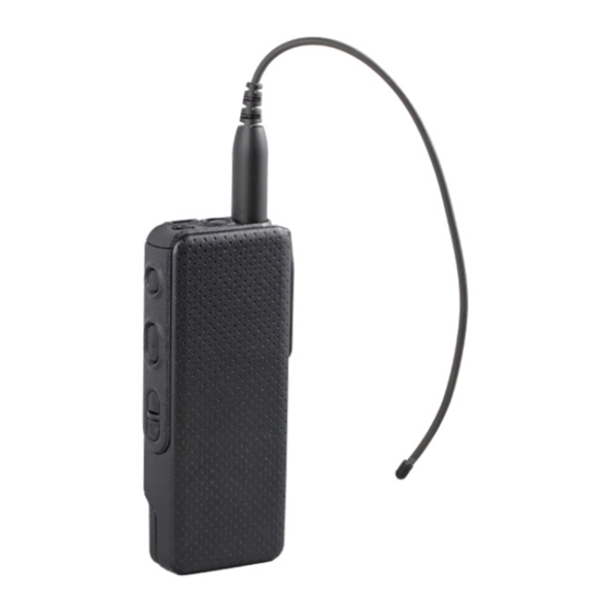
Page 29: Positioning Your Radio And Devices On Your Body
Positioning Your Radio and Devices on Your Body Installing the Flexible Antenna APX 3000 radio is designed to be operated while concealed With your radio turned off, set the antenna in its receptacle and under your outer garments. See the following pictures for the turn clockwise to attach it to your radio. - Page 30 • • Do not twist or coil the antenna because this To satisfy compliance with RF Exposure will result in antenna performance degradation. standards and improve radio performance, use See pictures below. the spacers provided to maintain a distance of a u t i o n a u t i o n 0.50 inch (1.27 cm) from your body.
-
Page 31: Strapping The Antenna Onto Your Body
Strapping the Antenna onto Your Body • To improve radio performance, secure the antenna as shown in picture below. Procedure: Ensure the spacer is upright when strapping it to a u t i o n the body. Position the spacers along the antenna to maintain 0.5 inch (1.27cm) from your body. -
Page 32: Identifying Radio Controls
The table below shows number of spacer segments for Identifying Radio Controls different antenna bands. Antenna Number of Number of Take a moment to review the following: Frequency spacers spacer Band provided* segments Radio Parts and Controls..... . . page 17 700 / 800 MHz Programmable Features . -
Page 33: Radio Parts And Controls
Radio Parts and Controls Top Button* Antenna On/Off Switch Bluetooth Pairing Transmit/ Spot Receive LED Top Side Button* Bluetooth Middle Side Button* Connector Cover Up Arrow Button* Down Arrow Button* Battery Battery Connector Battery Latch * These radio controls/buttons are programmable. English... -
Page 34: Programmable Features
Bluetooth – Clear All Bluetooth Pairing – Allows you to clear Programmable Features all pairing information for Bluetooth. This is accessed by a long press of the Bluetooth On/Off Button. Any reference in this manual to controls that are “preprogrammed” means that a qualified radio technician must Call Response –... -
Page 35: Assignable Settings Or Utility Functions
One Touch 1 – Launches a specific feature with one single Voice Announcement – Audibly indicates the current feature button-press. mode, Zone or Channel you has just assigned. Rekey Request – Notifies the dispatcher you require a new Voice Mute –... -
Page 36: Using Push-To-Talk (Ptt) Button
Your radio by default is set to use the primary feature. Short Identifying Status Indicators presses of MFB toggle to either the secondary or primary feature. Your radio indicates its operational status through the following: The secondary feature has an inactivity timer. This timer starts Status Icons‡... - Page 37 Direct Vote Scan Enabled The vote scan feature is enabled. • On = Radio is currently configured for direct radio to radio communication (during conventional operation only). Secure Operation • Off = Radio is connected with other radios • On = Secure operation. through a repeater.
-
Page 38: Led Indicator
LED Indicator The LED indicator shows the operational status of your radio. Transmit/ Receive LED Bluetooth Transmit/Receive LED Bluetooth LED Status Solid red – Radio is transmitting. Solid red Solid green Radio is upgrading the firmware. Blinking red – Radio is powering up with fatal error. Slow blinking red –... -
Page 39: Led Indicators In Surveillance Mode
Transmit/Receive LED Bluetooth LED Status Short blinking blue Solid green Radio is reading or upgrading by CPS. with long interval Blinking blue three – Bluetooth is powering on or off. times – Slow Blinking blue Radio is waiting to be paired when no device is connected with radio in Bluetooth. Blinking blue at –... -
Page 40: Intelligent Lighting Indicators
Intelligent Lighting Indicators‡ This feature temporary changes the backlight of the DRSM display screen to indicate a radio event has occurred. Note: This feature must be preprogrammed by a qualified radio technician. Backlight Notification When Your radio initiates an emergency alarm or call. Orange Emergency Alerts Your radio receives an emergency alarm or call. -
Page 41: Alert Tones
Alert Tones† An alert tone is a sound or group of sounds. Your radio uses alert tones to inform you of your radio’s condition. The following table lists these tones and when they occur. You can hear them using the Mission Critical Wireless Bluetooth headset or GCAI DRSM. You Hear Tone Name Heard... - Page 42 You Hear Tone Name Heard Valid Key-Press When a valid key is pressed. Radio Self Test Pass When radio passes its power-up self test. Clear Voice At beginning of a non-coded communication. Short, Priority Channel Medium-Pitched When activity on a priority channel is received. Received Tone Emergency Alarm/Call...
- Page 43 You Hear Tone Name Heard Short, High-Pitched Low-Battery Chirp When battery is below preset threshold value. Tone (Chirp) Ringing Phone Call Received When a land-to-mobile phone call is received. Dynamic Regrouping (When the PTT button is pressed) a dynamic ID has been received. Gurgle Talk Permit (When PTT button is pressed) verifying system accepting transmissions.
-
Page 44: General Radio Operation
Selecting a Zone† General Radio Operation A zone is a group of channels. Once you understand how your APX Portable is configured, you are ready to use your radio. Use the following procedure to select a zone. Use this navigation guide to familiarize yourself with the basic Note: Your radio must be preprogrammed to allow you to use Call features:... -
Page 45: Selecting A Radio Channel
Selecting a Radio Channel† Press the Up and Down Arrow Buttons or pre-programmed Channel up or down button to toggle the channel list backward or forward. If configured, you hear Voice A channel is a group of radio characteristics, such as transmit/ Announcement of the selected channel. -
Page 46: Using Mode Select Feature
Using Mode Select Feature Saving a Zone and Channel to a Mode Select Button† Mode Select allows a long press to save your radio’s current This feature allows to save two different zones or channels to a zone and channel to a programmable button. Once it saved, a preprogrammed button. -
Page 47: Receiving And Responding To A Radio Call
Receiving and Responding to a Radio Call Receiving and Responding to a Call‡ Procedure: Once you have selected the required channel and/or zone, you When you receive a call, depending on how your radio is can proceed to receive and respond to calls. preprogrammed: ASTRO Conventional Only: The LED lights up solid yellow. -
Page 48: Receiving And Responding To A Private Call (Trunking Only)
You cannot initiate a Private Call. Receiving and Responding to a Private Call (Trunking Only)†‡ Receiving and Responding to a Telephone Call A Private Call is a call from an individual radio to another (Trunking Only)†‡ individual radio. This feature allows you to receive calls similar to standard These one-to-one calls between two radios are not heard by phone calls from a landline phone. -
Page 49: Making A Radio Call
Making a Radio Call† Repeater or Direct Operation The REPEATER operation increases your radio’s range by Procedure: connecting with other radios through a repeater. The transmit and receive frequencies are different. Select a zone or channel by: Press the preprogrammed Zone or Channel Up Down The DIRECT or “talkaround operation”... -
Page 50: Monitoring Features
Monitoring Features†‡ Conventional Mode Operation ® Your radio may be preprogrammed to receive Private-Line Radio users who switch from analog to digital radios often (PL) calls. assume that the lack of static on a digital channel is an indication that your radio is not working properly. This is not the Procedure: case. -
Page 51: Advanced Features
Advanced Call Features Advanced Features Use this navigation guide to learn more about advanced Receiving and Responding to a Selective Call features available with your radio: (Conventional Only)†‡ Advanced Call Features ..... . . page 35 This feature allows you to receive a call from or to call a specific Scan . -
Page 52: Using The Dynamic Regrouping Feature (Trunking Only)
Using the Dynamic Regrouping Feature (Trunking Requesting a Reprogram (Trunking Only)†‡ Only)†‡ This feature allows you to notify your dispatcher when you want a new dynamic regrouping assignment. This feature allows the dispatcher to temporarily reassign selected radios to a particular channel where they can Procedure: communicate with each other. -
Page 53: Classifying Regrouped Radios
Scan Classifying Regrouped Radios Your dispatcher can classify regrouped radios into either of two This feature allows you to monitor traffic on different channels categories: Select Enabled or Select Disabled. by scanning a preprogrammed list of channels. • Select-enabled radios are free to change to any available channel, including the dynamic-regrouping channel, once you ‡... -
Page 54: Deleting A Nuisance Channel
Deleting a Nuisance Channel† Restoring a Nuisance Channel If a channel continually generates unwanted calls or noise Procedure: (termed a “nuisance” channel), you can temporarily remove the To restore the deleted nuisance channel, do one of the unwanted channel from the scan list. following: This capability does not apply to priority channels or the •... -
Page 55: Call Alert Paging
Call Alert Paging†‡ Emergency Operation†‡ This feature allows your radio to work like a pager. The Emergency feature is used to indicate a critical situation. If the Top button is preprogrammed to send an emergency Note: This feature must be preprogrammed by a qualified signal, this signal overrides any other communication over the radio technician. -
Page 56: Sending An Emergency Alarm
See Man Down†‡ on page 43 for details. Sending an Emergency Call (Trunking Only) This feature gives your radio priority access on a channel. Sending an Emergency Alarm Note: Your radio operates in the normal dispatch manner This feature lets you send a data transmission, which identifies while in Emergency Call, except, if enabled, it returns your radio sending the emergency, to your dispatcher. -
Page 57: Sending An Emergency Alarm With Emergency Call
Note: The timer of this long press can be preprogrammed. Release the PTT button to end the transmission and wait for Consult your qualified technician to program the a response from your dispatcher. duration required. Press and hold the preprogrammed Emergency button until your radio exits the Emergency Call mode. -
Page 58: Sending A Silent Emergency Alarm
Sending a Silent Emergency Alarm Using the Emergency Keep-Alive Feature This feature allows you to send an Emergency Alarm to another This feature, when enabled, prevents your radio from being radio without any audio or visual indicators. turned off via the On/Off Switch when your radio is in the Emergency state. -
Page 59: Man Down
The Man Down feature has three phases: Down†‡ Your radio senses the Man Down condition and Pre-Alert Man Down condition is determined based upon your radio tilt Timer is initiated. angle or a combination of radio tilt angle and the lack of radio Man Down condition continues for the time duration defined motion. -
Page 60: Pre-Alert Timer
Note: Emergency must be set up for this feature to operate. Post-Alert Timer For details on operating the Emergency alerts, please This timer sets the amount of time your radio needs to remain in see Emergency Operation†‡ on page 39. the Man Down condition before the Emergency alarm is transmitted. -
Page 61: Triggering Emergency
Triggering Emergency Re-Initiating Man Down When you have not clear the Man Down condition and the Post- After exiting the Emergency Operation when your radio is still in Alert Timer comes to an end, Emergency Alarm or call is Man Down condition (tilted achieving threshold angle or triggered. -
Page 62: Testing The Man Down Feature
Testing the Man Down Feature Handling Man Down Functional Error Messages Procedure: Note: Enable the Emergency feature with Silent Alarm disabled, but not in Surveillance Mode before running If your radio display shows one of the following error this test on your radio. -
Page 63: Secure Operations
Note: If the selected channel is preprogrammed for secure- Unlike other forms of security, Motorola digital encryption only operation – when you press the PTT button, an provides signaling that makes it virtually impossible for others to invalid mode tone sounds and the display shows SEC decode any part of an encrypted message. -
Page 64: Managing Encryption
Managing Encryption Using the Multikey Feature This feature allows your radio to be equipped with different † Loading an Encryption Key encryption keys and supports the DES-OFB algorithm. Note: Refer to the key-variable loader (KVL) manual for There are two types: equipment connections and setup. -
Page 65: Erasing All The Selected Encryption Keys
Erasing All the Selected Encryption Keys‡ Requesting an Over-the-Air Rekey (ASTRO Only)†‡ This feature allows you to erase all or selected encryption keys. This feature, also known as OTAR, allows your dispatcher to reprogram the encryption keys in your radio remotely. Your Procedure: dispatcher performs the rekey operation upon receiving a rekey request from you. -
Page 66: Mdc Over-The-Air Rekeying (Otar) Page
MDC Over-the-Air Rekeying (OTAR) Page Hear Clear † This feature allows to view or define MDC Over-the-Air There are two components of Hear Clear. Rekeying (OTAR) features.It is applied only when operating in Companding: secure encrypted mode and only for conventional Reduces the channel noise, e.g. -
Page 67: Using Radio Kill
‡ Trunking System Controls†‡ Using Radio Kill This feature allows you to render your radio or another radio inoperable if the radio is misplaced or lost. When a radio is Using the Failsoft System killed, the DRSM display turns blank and all functions of the The failsoft system ensures continuous radio communications radio are not usable. -
Page 68: Going Out Of Range
Going Out of Range Using the Site Trunking Feature When your radio goes out of the range of the system, it can no If the zone controller loses communication with any site, that longer lock onto a control channel. site reverts to site trunking. -
Page 69: Mission Critical Wireless - Bluetooth
Turning the Bluetooth Off This feature allows your radio to extend its functionality by Procedure: connecting to external proprietary Motorola Accessories. Press the preprogrammed button to turn the Bluetooth off. The default setting for a Bluetooth-enabled radio is Bluetooth The Blue LED blinks three times, a short, medium-pitched ON. -
Page 70: Bluetooth Drop Timer
can resume the Bluetooth connection without your Bluetooth Drop Timer intervention. The Bluetooth Drop Timer has two different settings and functions, depending upon the selection of the Re-Pair Timer. Re-Pair Timer Re-Pair Timer Re-Pair Timer Scenarios Drop Timer Options Options Options •... -
Page 71: Pairing The Bluetooth Device With Your Radio
Procedure: Pairing the Bluetooth Device with Your Radio Note: Bluetooth tones and Bluetooth preprogrammed buttons must be preprogrammed by a qualified radio technician. Check with your dealer or system administrator for more information. Bluetooth Pairing To view the Bluetooth LED state, your radio must not Spot be in Surveillance mode during the pairing process. -
Page 72: Indicating The Bluetooth Connection Is Lost
If the device already has pairing records and the connecting sounds an decremental-pitched tone and the display shows process fails, the blue LED blinks rapid blue for two seconds <Device Type> alternates with CON LOST. and your radio sounds a short, low-pitched tone. Your radio If the Bluetooth device successfully re-connects before the display shows <Device Type>... -
Page 73: Turning The Bluetooth Audio Off (Routing The Audio From The Headset To Your Radio)
Turning the Bluetooth Audio Off (Routing the Clearing All Bluetooth Devices Information Audio from the Headset to Your Radio) Long press the preprogrammed Bluetooth On/Off button. Your radio sounds a short, medium-pitched tone. Procedure: Your radio display shows PLS WAIT and the blue LED blinks With the external device Bluetooth turned ON. -
Page 74: Programming Over Project 25 (Pop 25) (Astro 25 And Astro Conventional)
Programming Over Project 25 (POP 25) Utilities (ASTRO 25 and ASTRO Conventional) Flipping the Display on DRSM‡ This feature enables configuration data to be upgraded to your This feature allows you to reverse the content of your DRSM radio over-the-air. This feature retains full use of your radio display upside down. -
Page 75: Locking And Unlocking The Controls
Locking and Unlocking the Controls†‡ Turning Voice Mute On or Off†‡ You can lock your radio’s programmable buttons to avoid You can enable and disable voice transmission, if needed. inadvertent entry. This function can be preprogrammed as a Procedure: short press or long press per your request. -
Page 76: Using The Conventional Squelch Operation Features
Procedure: Using the Conventional Squelch Operation Features Hold down the PTT button longer than the preprogrammed time. You hear a short, low-pitched warning tone, the This feature filters out unwanted calls with low signal strength or transmission is cut-off, and the LED goes out until you channels that have a higher than normal background noise. -
Page 77: Using The Digital Ptt Id Feature
Three variations of smart PTT are available: Option Result Transmit Inhibit You hear any digital traffic having You cannot transmit if any traffic is on Busy Channel Selective Switch the correct network access code detected on the channel. with Carrier and correct talkgroup. -
Page 78: Voice Announcement
• Your radio powers up. Your radio announces the current zone Voice Announcement† and channel it is transmitting. This feature enables your radio to audibly indicate the current • Press the preprogrammed voice announcement button feature mode, Zone or Channel you have just assigned. This (which specifically programmed to playback the current zone audio indicator can be customized per customer requirements. -
Page 79: Helpful Tips
Troubleshooting Helpful Tips Scenario Solution Take a moment to review the following: LED indicator on The radio might be preprogrammed in Troubleshooting......page 63 the radio is not lights off mode in the current channel. -
Page 80: Caring For Your Radio
Caring for Your Radio • The radio is designed to be submerged to a maximum depth of 1 meter, with a maximum submersion time of 30 minutes. Exceeding • The radio casting has a a u t i o n either maximum limit may result in damage to vent port that allows for the radio. -
Page 81: Cleaning Your Radio
Cleaning Your Radio Handling Your Radio • Procedure: Do not pound, drop, or throw your radio unnecessarily. Never carry your radio by the antenna. To clean the external surfaces of your radio: • Avoid subjecting your radio to an excess of liquids. Combine one teaspoon of mild dishwashing detergent to one gallon of water (0.5% solution). -
Page 82: Servicing Your Radio
Battery†‡ Servicing Your Radio Proper repair and maintenance procedures will assure efficient operation and long life for this product. A Motorola maintenance Checking the Battery Charge Status agreement will provide expert service to keep this and all other Your radio can indicate the battery’s charge status through:... -
Page 83: Battery Recycling And Disposal
Battery Recycling and Disposal Gauge Battery Charge In the U.S. and Canada, Motorola participates in the nationwide Rechargeable Battery Recycling Corporation (RBRC) program 76% to 100% full* for battery collection and recycling. Many retailers and dealers participate in this program. -
Page 84: Accessories
Accessories Only the following programming cable is compatible with The accessory link below is for your APX radios. Not all APX 3000 radios. accessories are FCC certified for operation with all APX models – APX DMR Port Programming Cable (PMKN4012B) and/or bandsplits. -
Page 85: Appendix: Maritime Radio Use In The Vhf Frequency Range
State the position of the vessel in distress, using any Appendix: Maritime Radio Use in the information that will help responders to locate you, e.g.: VHF Frequency Range • latitude and longitude • bearing (state whether you are using true or magnetic Take a moment to review the following: north) Special Channel Assignments . -
Page 86: Operating Frequency Requirements
Table A-1: VHF Marine Channel List (Continued) Operating Frequency Requirements Frequency (MHz) Channel A radio designated for shipboard use must comply with Federal Number Transmit Receive Communications Commission Rule Part 80 as follows: 156.150 160.750 • on ships subject to Part II of Title III of the Communications Act, the radio must be capable of operating on the 156.800 156.200 160.800... - Page 87 Table A-1: VHF Marine Channel List (Continued) Table A-1: VHF Marine Channel List (Continued) Frequency (MHz) Frequency (MHz) Channel Channel Number Number Transmit Receive Transmit Receive 157.150 161.750 157.200 161.800 157.250 161.850 77** 156.875 – 157.300 161.900 156.925 161.525 157.350 161.950 156.975 161.575...
-
Page 88: Declaration Of Compliance For The User Of Distress And Safety Frequencies
Declaration of Compliance for the User of Distress and Safety Frequencies The radio equipment does not employ a modulation other than the internationally adopted modulation for maritime use when it operates on the distress and safety frequencies spedified in RSS-182 Section 6.1. Table A-2: Technical Paratmeters for Interfacing External Data sources RS232... -
Page 89: Glossary
Automatic Registration Service signal is being received so that the user does not have to listen to “noise”. Motorola standard for wireless digital ASTRO 25 trunked communications. A software-controlled, computer-driven device that receives and generates data for... - Page 90 Term Definition Term Definition In a trunking system, one of the channels A feature that allows the dispatcher to that is used to provide a continuous, two- Dynamic temporarily reassign selected radios to a Control Channel way/data communications path between Regrouping single special channel so they can the central controller and all radios on the...
- Page 91 Term Definition Term Definition A life-saving feature that senses the radio The user talks on a preprogrammed Non-Tactical/ user may be in trouble by monitoring emergency channel. The emergency alarm Revert whether the radio is in a vertical or is sent out on this same channel. horizontal position or whether the radio is OTAR Over-the-air rekeying.
- Page 92 Term Definition Term Definition A conventional radio feature, where you The user talks on the channel that was Tactical/ talk through a receive/transmit facility that selected before the radio entered the Non-Revert Repeater re-transmits received signals, in order to emergency state. improve communications range and Bypass a repeater and talk directly to coverage.
-
Page 93: Commercial Warranty
Product manufactured by MOTOROLA. MOTOROLA assumes no Commercial Warranty obligations or liability for additions or modifications to this warranty unless made in writing and signed by an officer of MOTOROLA. Limited Warranty Unless made in a separate agreement between MOTOROLA and the original end user purchaser, MOTOROLA does not warrant the installation, maintenance or service of the Product. - Page 94 Product for which it and insurance prepaid, to an authorized warranty service location. is specified. Warranty service will be provided by MOTOROLA through one of its H)Freight costs to the repair depot. authorized warranty service locations. If you first contact the I) A Product which, due to illegal or unauthorized alteration of the company which sold you the Product (e.g., dealer or...
- Page 95 VI. PATENT AND SOFTWARE PROVISIONS: MOTOROLA will have no liability with respect to any claim of patent infringement which is based upon the combination of the Product or MOTOROLA will defend, at its own expense, any suit brought parts furnished hereunder with software, apparatus or devices not...
- Page 96 Motorola Solutions Australia’s limited warranty below is in addition to any rights and remedies you may have under the Australian Consumer Law. If you have any queries, please call Motorola Solutions Australia at 1800 457 439. You may also visit our website: http://www.motorola.com/Business/XA-EN/...
- Page 98 Stylized M logo are trademarks or registered trademarks of Motorola Trademark Holdings, LLC and are used under license.All other trademarks are the property of their respective owners. © 2012 – 2013 Motorola Solutions, Inc. All rights reserved. May 2013. *68012007043* 68012007043-C...