Brother MFC5100C Service Manual
Facsimile equipment
Hide thumbs
Also See for MFC5100C:
- Owner's manual (180 pages) ,
- Quick setup manual (6 pages) ,
- Owner's manual (213 pages)
Table of Contents
Advertisement
Quick Links
Download this manual
See also:
Owner's Manual
Advertisement
Chapters
Table of Contents
Troubleshooting

Related Manuals for Brother MFC5100C


Summary of Contents for Brother MFC5100C
- Page 1 FACSIMILE EQUIPMENT SERVICE MANUAL MODEL: MFC5100C/MFC590...
- Page 2 © Copyright Brother 2001 All rights reserved. No part of this publication may be reproduced in any form or by any means without permission in writing from the publisher. Specifications are subject to change without notice.
- Page 3 PREFACE This publication is a Service Manual covering the specifications, construction, theory of operation, and maintenance of the Brother facsimile equipment. It includes information required for field troubleshooting and repair--disassembly, reassembly, and lubrication--so that service personnel will be able to understand equipment function, to rapidly repair the equipment and order any necessary spare parts.
- Page 4 CHAPTER GENERAL DESCRIPTION...
- Page 5 CHAPTER 1 GENERAL DESCRIPTION CONTENTS EQUIPMENT OUTLINE ....................1-1 1.1.1 External Appearance and Weight ................1-1 1.1.2 Components ......................1-1 SPECIFICATIONS......................1-2...
-
Page 6: Equipment Outline
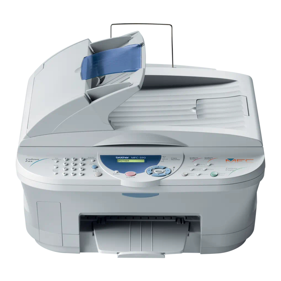
1.1 EQUIPMENT OUTLINE 1.1.1 External Appearance and Weight The figure below shows the equipment appearance and approximate dimensions. 467 mm 18.4" 370 mm 14.6" 468 mm 18.4" (including handset) Weight: Machine proper Approx. 15 kg (33.1 lbs.) In package Approx. 11 kg (24.2 lbs.) 1.1.2 Components The equipment consists of the following major components: ADF &... -
Page 7: Specifications
Scan Speed (A4:Standard) Approx. 3 sec./page (A4: standard) Memory Transmission (Brother#1 Chart) Yes (200:MMR) Memory Transmission (ITU-T Chart) Yes (170:MMR) Out-of-Paper Reception (Brother #1 Chart) Yes (200:MMR) Out-of-Paper Reception (ITU-T Chart) Yes (170:MMR) Color FAX (Document Send/Receive) Yes/Yes Color FAX (Memory Send/Receive) - Page 8 (2/2) Model Name MFC-5100C INTERFACE External TAD Interface Host Interface (IEEE1284) Host Interface (USB) LAN Interface PRINTER Color/Mono Color/Mono Engine Type Piezo Ink Jet (2-head BH: 75 nozzles/color) Resolution (dpi) 1200x1200 /2400x1200 (Mono/Color) 10/8 (Mono/Color: 600*150) 4/3.5 (Mono/Color: 600*300) Speed (ppm) 2/1.5 (Mono/Color: 600*600) 0.2/0.2 (Mono/Color: 1200*1200/2400*1200) Paper Capacity (sheets)
- Page 9 Scan Speed (A4:Standard) Approx. 3 sec./page (A4: standard) Memory Transmission (Brother#1 Chart) Yes (200:MMR) Memory Transmission (ITU-T Chart) Yes (170:MMR) Out-of-Paper Reception (Brother #1 Chart) Yes (200:MMR) Out-of-Paper Reception (ITU-T Chart) Yes (170:MMR) Color FAX (Document Send/Receive) Yes/Yes Color FAX (Memory Send/Receive)
- Page 10 (2/2) Model Name MFC-590 PRINTER Color/Mono Color/Mono Engine Type Piezo Ink Jet (2-head BH: 75 nozzles/color) Resolution (dpi) 1200x1200 /2400x1200 (Mono/Color) 10/8 (Mono/Color: 600*150) 4/3.5 (Mono/Color: 600*300) Speed (ppm) 2/1.5 (Mono/Color: 600*600) 0.2/0.2 (Mono/Color: 1200*1200/2400*1200) Paper Capacity (sheets) Output Paper Capacity (sheets) Standard Print Language Windows GDI Emulation...
- Page 11 CHAPTER INSTALLATION...
- Page 12 CHAPTER 2 INSTALLATION CONTENTS INSTALLING THE UPDATE DATA TO THE FACSIMILE MACHINE......2-1 SETTING ID CODES TO FACSIMILE MACHINES ............2-3 UPDATING HEAD PROPERTY INFO STORED IN THE FACSIMILE MACHINE ..2-5...
-
Page 13: Installing The Update Data To The Facsimile Machine
2.1 INSTALLING THE UPDATE DATA TO THE FACSIMILE MACHINE If you want to update the current program stored in the flash ROM of the main PCB to the newer version or after you replace the main PCB, install the update program onto the flash ROM. The program installation requires a PC/AT-compatible computer (which is capable of running MS-DOS or its compatible OS). - Page 14 Installing the update data onto the flash ROM of the facsimile machine NOTE: The following is an installation procedure example on a PC that is running Windows 95/98. (1) Copy the update data and transfer utility onto the desired directory of the hard disk. e.g., C:\UPDATE (2) Click the Start button, point to Programs, and then click MS-DOS Prompt to open an MS-DOS window.
-
Page 15: Setting Id Codes To Facsimile Machines
2.2 SETTING ID CODES TO FACSIMILE MACHINES Brother facsimile machines are assigned unique ID codes (character strings) at the factory. If you replace the main PCB of the machine, the machine will lose its assigned ID code so that it will not be identified by the connected PC*. - Page 16 The setup utility will transmit the ID code data from your PC to the facsimile machine and then it will terminate. The facsimile machine will automatically return to the standby mode. (3) To check whether the entered character string (ID code) is correct, make the machine enter the maintenance mode (refer to CHAPTER 5, Section 5.1) and then press the 1 key twice (Subsection 5.3.6).
- Page 17 2.3 UPDATING HEAD PROPERTY INFO STORED IN THE FACSIMILE MACHINE To keep the print quality, the controller optimizes the head drive strength, ink jet-out timing, and other drive conditions according to the electromechanical properties unique to individual print heads and ambient temperature. The head property information is stored in the EEPROM of the main PCB.
- Page 18 In the Head Info. box, type upper 12 digits (e.g., 66667F657031) out of the 13-digit property code (enclosed with asterisks, e.g., *66667F657031H*) which is printed on the bar code label attached to the print head unit. Then press the Enter key. The setup utility will transmit the entered data from your PC to the facsimile machine and then it will terminate.
-
Page 19: Theory Of Operation
CHAPTER THEORY OF OPERATION... -
Page 20: Table Of Contents
CHAPTER 3 THEORY OF OPERATION CONTENTS OVERVIEW ........................3-1 MECHANISMS .........................3-2 3.2.1 Scanner Mechanism ....................3-4 3.2.2 Ink Jet Printing Mechanism ..................3-6 3.2.2.1 Paper pulling-in, registration, feeding, and ejecting mechanisms....3-6 3.2.2.2 Ink jet printing and capping mechanisms.............3-8 3.2.2.3 Purging mechanism ...................3-11 3.2.2.4 Carriage drive mechanism .................3-14 3.2.3 Sensors and Actuators ..................3-15... -
Page 21: Overview
3.1 OVERVIEW 3 -1... -
Page 22: Mechanisms
3.2 MECHANISMS The facsimile machine is classified into the following mechanisms: SCANNER MECHANISM - ADF mechanism - Document scanning mechanism INK JET PRINTING MECHANISM - Paper pulling-in, registration, feeding, and ejecting mechanisms - Ink jet printing and head capping mechanisms - Purging mechanism - Carriage drive mechanism SENSORS AND ACTUATORS... - Page 23 Ink jet printing and head capping mechanisms Purge mechanism Carriage drive mechanism INK JET PRINTING MECHANISM Paper pulling-in, registration, feeding, and ejecting mechanisms 3 -3...
- Page 24 3.2.1 Scanner Mechanism This mechanism consists of the document guide base, ADF & document tray ASSY and scanner unit. The ADF (automatic document feeder) unit contains a separation roller ASSY, document feed roller ASSY, document ejection roller, ADF motor, and document front and rear sensors. The scanner unit consists of a scanner top cover, CCD unit, CCD drive mechanism, CCD HP sensor, and scanner base.
- Page 25 This scanner mechanism supports a dual scanning system. (1) If you set documents on the document guide base with their faces up and start the scanning operation, then the ADF motor rotates to pull in those documents into the ADF unit, starting from the top sheet to the bottom, page by page.
-
Page 26: Ink Jet Printing Mechanism
3.2.2 Ink Jet Printing Mechanism 3.2.2.1 Paper pulling-in, registration, feeding, and ejecting mechanisms The paper pulling-in, registration, feeding, and ejecting mechanisms are driven by a single paper feed motor located at the left side of the main chassis via the gear train. (See the illustration given on the next page.) First, the paper feed motor rotates clockwise (when viewed from the output gear). - Page 27 Gear 31MF Gear shaft 17 ASF roller unit PF roller gear R Gear 39 Paper feed roller Gear 25 ASF-purge switching gear 23 ASF/purge idle gear PF roller gear Paper feed motor 3 -7...
-
Page 28: Ink Jet Printing And Capping Mechanisms
3.2.2.2 Ink jet printing and capping mechanisms (1) Print head unit This machine uses drop-on-demand ink jet printing. Each of the right and left print heads has an ink-jet unit that has a pair of nozzle columns for two color inks. A nozzle column consists of 75 nozzles, 75 channels covered with piezoelectric ceramic (PZT), a manifold, and filter. - Page 29 If the controller issues a print command, a biased voltage will be applied to all electrodes formed on the surface of the piezoelectric ceramic so that each actuator will be distorted as shown with broken lines. If the electrodes on a target channel are deenergized according to drive signals, then the associated piezoelectric ceramic actuator returns to the previous form so that the ink in the manifold will be vacuumed out to the channel.
- Page 30 (3) Head caps Shown below is a head cap mechanism that prevents the nozzles of the print heads from drying up when they are not in use. Upon completion of printing, the carriage travels to the right and moves the head cap holder provided on the purge unit to the right together.
-
Page 31: Purging Mechanism
3.2.2.3 Purging mechanism The purge mechanism is driven by the paper feed motor located at the left side of the main chassis. As described in Subsection 3.2.2.1, the motor rotation is transmitted to the ASF/purge idle gear at the right side of the main chassis. Engaged with the ASF/purge idle gear, the ASF-purge switching gear 23 works as a clutch gear. - Page 32 During printing: The ASF-purge switching gear 23 is During purging: The ASF-purge not engaged with purge bevel gear A (but engaged with switching gear 23 is engaged with gear 25 in the ASF gear train). purge bevel gear A. When the motor rotation is transmitted to the purge unit, its counterclockwise rotation will drive the purge cam and its clockwise rotation, the pump switching unit (when viewed from the output gear of the motor).
- Page 33 The purge cam is so designed that: - the carriage lock pops out to lock the carriage before purging and pops in before cleaning with the head wiper (see the illustration below), - the pump works to draw out ink from each of the four head nozzles and drain it to the ink absorber felts, and - the head wiper comes out to clean the nozzle surface (see the illustration below).
-
Page 34: Carriage Drive Mechanism
3.2.2.4 Carriage drive mechanism The carriage motor controls horizontal motion. The motor rotation is transmitted via the motor pulley to the timing belt. The carriage, which is supported and guided by the carriage rail, is secured to the timing belt. Clockwise and counterclockwise rotations of the carriage motor move the carriage to the right and left, respectively. -
Page 35: Sensors And Actuators
3.2.3 Sensors and Actuators This machine has the following sensors and thermister. Sensor name Type Located on Document front sensor Photosensor Document sensor PCB in the ADF Document rear sensor Photosensor Document tray open sensor Mechanical switch Document tray Scanner open sensor Photosensor Control panel PCB ASSY Registration sensor... - Page 36 • Purge cam HP switch which detects whether the purge cam is in the home position. • Pump switching cam HP switch which detects whether the pump switching cam is in the home position. These photosensors (except the ink empty sensor that is a reflection type) are a photointerrupter consisting of a light-emitting diode and a light-sensitive transistor.
- Page 37 Location of Sensors and Actuators 3 -1 7...
-
Page 38: Control Electronics
3.3 CONTROL ELECTRONICS 3.3.1 Configuration The hardware configuration of the facsimile machine is shown below. Configuration of Facsimile Machine 3 -1 8... - Page 39 CHAPTER DISASSEMBLY/REASSEMBLY, LUBRICATION, AND ADJUSTMENT...
- Page 40 CHAPTER 4 DISASSEMBLY/REASSEMBLY, LUBRICATION, ADJUSTMENT CONTENTS DISASSEMBLY/REASSEMBLY..................4-1 Safety Precautions .......................4-1 Tightening Torque List......................4-2 Preparation ........................4-4 How to Access the Object Component ................4-4 Disassembly Order Flow....................4-5 4.1.1 Print Head Unit .....................4-6 4.1.2 ADF Cover and Document Guide Base .............4-10 4.1.3 ADF Components on the Upper ADF Chute ............4-11 Gear cover ......................4-11 Separation roller ASSY and document feed roller ............4-12 Separation rubber unit, ADF thickness adjuster, and pressure rollers ......4-13...
- Page 41 4.1.11 Edge Cover, Scanner Links and Their Guides...........4-36 4.1.12 Relay PCB and PCB Plate .................4-37 4.1.13 Bottom Plate, Ink Absorber Box, Main PCB, NCU PCB, and Power Supply PCB .....................4-38 4.1.14 Enclosure Cover....................4-42 4.1.15 Main Cover ......................4-43 4.1.16 Purge Unit ......................4-45 4.1.17 Main Chassis......................4-47 4.1.18 ASF Roller Unit and its Related Gears...............4-49 4.1.19 Paper Pressure Holders ..................4-51...
-
Page 42: Disassembly/Reassembly
4.1 DISASSEMBLY/REASSEMBLY Safety Precautions To prevent the creation of secondary problems by mishandling, observe the following precautions during maintenance work. (1) Unplug the power cord from the power outlet before replacing parts or units. When having access to the power supply, be sure to unplug the power cord from the power outlet. (2) Be careful not to lose screws, washers, or other parts removed for parts replacement. -
Page 43: Tightening Torque List
Tightening Torque List Location Screw type Q'ty Tightening torque N•m (kgf•cm) ADF thickness adjuster Taptite, pan B M3x6 0.39 ±0.10 (4 ±1) Upper ADF chute Taptite, cup B M3x10 0.69 ±0.10 (7 ±1) Lower ADF chute Taptite, cup B M3x10 0.69 ±0.10 (7 ±1) Grounding wire... - Page 44 Location Screw type Q'ty Tightening torque N•m (kgf•cm) ASF roller unit Taptite, cup S M3x6 0.98 ±0.10 (10 ±1) ASF gear holders Taptite, cup B M3x10 0.49 ±0.10 (5 ±1) Paper chute Taptite, cup S M3x6 0.98 ±0.10 (10 ±1) Ink empty sensor PCB Taptite, cup B M3x8 0.59 ±0.10...
-
Page 45: Preparation
Preparation Prior to proceeding to the disassembly procedure, (1) Unplug - the modular jack of the telephone line, - the PC interface cable if connected (Not shown below), and - the modular jack of an external telephone set if connected (Not shown below). (2) Remove - the paper wire extension and - the paper tray. -
Page 46: Disassembly Order Flow
Disassembly Order Flow (NOTE 5) (NOTE 1) (NOTE 2) (NOTE 4) (NOTE 3) (NOTE 6) (NOTE 7) (NOTE 8) (NOTE 9) 4 -5... -
Page 47: Print Head Unit
4.1.1 Print Head Unit During disassembly jobs (except when removing the purge unit, carriage rail, or carriage ASSY), the print head unit and all the four ink cartridges should be kept in place. NOTE: To replace the print head unit with a new one, you need to move the carriage to the ink replacement position by placing the machine in the ink replacement mode. - Page 48 (8) Pull the head clamp springs in the direction of arrows shown below to release the print head unit. (9) Lift the print head unit up and out of the carriage (arrow Correct Wrong Wrong NOTE: Do not touch the printing ends (nozzles) of the print head unit or the ink orifices of the ink cartridges;...
- Page 49 NOTE: Once the ink cartridges are removed, their colored covers rise upright. If you turn the machine upside down with those covers being upright, then they will break. To prevent it, set them to the horizontal position by turning them in the direction of arrow and pushing them up in the direction of arrow (10) Turn the head adjuster lever located on the right side of the carriage to position 1.
- Page 50 (13) Press the front center of the carriage to the rear and move the print head unit to the right and left several times. This is to assure the dimple contact between the head PCB and carriage PCB. (14) Remove the head filter seal. (15) While pressing the center of the print head unit as shown above, lock the print head unit with the head clamp springs.
-
Page 51: Adf Cover And Document Guide Base
4.1.2 ADF Cover and Document Guide Base (1) Open the ADF cover, press its front end to release the boss, and take it off (in the direction of arrows , and (2) Remove the document support. (3) Release the two latches of the document guide base and slide it up straight along the guides. NOTE: Do not turn it to the left. -
Page 52: Adf Components On The Upper Adf Chute
4.1.3 ADF Components on the Upper ADF Chute Gear cover (1) As illustrated below, insert the tip of a flat screwdriver into the slot and lift up the right edge of the gear cover (arrow ) and move the gear cover to the front (arrow 4 -1 1... -
Page 53: Separation Roller Assy And Document Feed Roller
Separation roller ASSY and document feed roller (2) From the rear end of each of the separation roller ASSY and document feed roller, remove the plastic retaining ring. Lift up the rear ends of them and take them out together with bushings NOTE: Take care not to drop bushings S. -
Page 54: Separation Rubber Unit, Adf Thickness Adjuster, And Pressure Rollers
Reassembling Note: If you have disassembled the separation roller ASSY, set the separation roller on its shaft with the boss facing towards the pin and then snap the plastic retaining ring into place, as illustrated below. Reassembling Note: When setting the separation roller ASSY, take care not to apply force to the spring plate at an angle, as illustrated on the previous page. - Page 55 (4) Remove the screw and take the ADF thickness adjuster out of the upper ADF chute. NOTE: The ADF thickness adjuster is lubricated with grease, so take care not to smear surrounding parts with the grease when handing the ADF thickness adjuster. (5) At either end of the pressure roller shaft, press the latch to the right and take out the pressure rollers and their shaft.
-
Page 56: Upper Adf Chute
Upper ADF chute (6) Remove the two screws from the upper ADF chute. (7) Open the document tray ( ). (8) From the underside of the document tray, release the two leftmost latches ( ) and then pull up the left end of the upper ADF chute ( ). Reassembling Note: When latching the upper ADF chute, first fit tabs (1) of the right end into the openings provided in the document tray, then press latches (2), (3), and (4) into place in this order as shown above. -
Page 57: Adf Components On The Lower Adf Chute
4.1.4 ADF Components on the Lower ADF Chute Document front and rear sensor actuators (1) Lift up the document front sensor actuator. Fully turn the document rear sensor actuator counterclockwise, then lift it up. Document sensor PCB (2) Take the document sensor harness out of the cable hooks, then disconnect it from the document sensor PCB. -
Page 58: Document Guide Clips
Document guide clips (4) Press the tab of each document guide clip. Each clip will snap out of the document ejection roller shaft. Document ejection roller (5) Remove the pawled bushing from the front end of the document ejection roller shaft by pulling its pawls outwards. -
Page 59: Document Pressure Bar
Reassembling Note: When fitting the rear bushing of the document ejection roller into the cutout of the ADF drive unit, orient the boss as illustrated on the previous page. Document pressure bar (7) Open the ADF & document tray ASSY. (8) Pull either of the front and rear supports of the document pressure bar outwards and remove the document pressure bar. -
Page 60: Lower Adf Chute, Pinch Rollers, And Adf Motor
Lower ADF chute, pinch rollers, and ADF motor (9) Take the document sensor harness out of cable hooks provided on the lower ADF chute. (10) Disconnect the ADF motor harness from the motor, then take its harness out of the cable guides and hooks. - Page 61 (15) Remove the two screws from the ADF drive unit and release the ADF motor. NOTE: When using a screwdriver, take care not to scratch or damage gears on the ADF drive unit. Reassembling Note: When setting the ADF motor, hook the non-screw side of the flange on section "x"...
-
Page 62: Document Tray Open Sensor And Document Stopper
4.1.5 Document Tray Open Sensor and Document Stopper (1) Disconnect the document tray open sensor harness from the sensor. (2) Open the document tray. (3) Press the right and left latches of the document tray open sensor with the tip of a flat screwdriver as shown below and push it down. -
Page 63: Jam Clear Cover, Rear Cover, And Inner Cover
4.1.6 Jam Clear Cover, Rear Cover, and Inner Cover (1) Open the jam clear cover and remove it while warping it. (2) Remove the two screws from the rear cover and take if off to the rear. (3) Slightly pull up the rear edge of the inner cover and pull it out to the rear. 4 -2 2... -
Page 64: Scanner Unit And Control Panel Assy (Together With Document Tray)
4.1.7 Scanner Unit and Control Panel ASSY (Together with Document Tray) (1) Release the grounding wires (coming from the ADF drive unit and relay PCB) by removing the screw. (2) Disconnect the following harnesses and flat cable from the relay PCB: - CCD flat cable - Document tray open sensor harness - Document sensor harness... - Page 65 (3) Pull the scanner open lever towards you and open the scanner unit. (4) At each of the right and left scanner links, fully push up the lock of the scanner link support (in the direction of arrow ) and press the upper end of the scanner link inwards (arrow to release its boss from the scanner link support.
- Page 66 (6) Remove the two screws from the bottom rear of the hinges. (7) Be sure to open the document tray, then release the harnesses (bound and covered with the cable sheath) from the latch and move them to the front in the opening. (8) Lift up the document tray.
- Page 67 (11) Remove the six screws from the underside of the scanner base. (12) Slightly lift up the control panel ASSY and disconnect the panel harness and piezo ringer harness from the control panel PCB. (13) Turn the scanner open sensor actuator as shown below and remove it. (14) Remove the screw from the scanner open sensor PCB.
- Page 68 Reassembling Notes • When setting the document tray on the scanner unit, pass the bound harnesses (ADF motor harness, document sensor harness, document tray open sensor harness, and grounding wire) through the front section of the opening provided in the left rear corner of the document tray, with its bound section facing up (see the illustration given on page 4-25).
-
Page 69: Disassembly Of The Control Panel Assy
4.1.8 Disassembly of the Control Panel ASSY (1) Remove the two screws from the control panel PCB. (2) Slightly lift up the control panel PCB, then unlock the FPC key connector and disconnect the FPC key. Next, unlock the LCD cable connector and disconnect the LCD flat cable. (3) Remove the seven screws and take off the reinforcement plate and FPC key. -
Page 70: Disassembly Of The Scanner Unit
4.1.9 Disassembly of the Scanner Unit The disassembly job of the scanner unit should be done in a clean room to prevent dust or dirt from getting into the scanner unit. (1) Remove the four screws from the scanner top cover. (2) Separate the scanner top cover from the scanner base. - Page 71 (3) Release the CCD drive belt from boss "a." (4) At the left front end of the CCD drive belt, unhook the belt spring from boss "b." NOTE: Do not remove the belt spring or belt clip from the CCD drive belt. (5) As illustrated below, move the CCD unit to the right, lift up its front end and turn the CCD unit upright.
- Page 72 (6) Disconnect the CCD flat cable from the CCD PCB, then release the cable that is attached to the underside of the CCD unit with double-sided adhesive tape. NOTE: Only when the CCD unit or CCD flat cable is defective and requires replacement, release the flat cable.
- Page 73 (8) Remove the three screws and lift up the guide plate. (9) Remove the screw from the CCD HP sensor plate. 4 -3 2...
- Page 74 (10) Remove the two screws and take off the flat cable clamp. (11) To take out the panel harness, remove sponges F and R that are backed with adhesive tape. NOTE: Once removed, those sponges will become unusable and new parts will have to be put back in.
-
Page 75: Auto Sheet Feeder (Asf) And Separation Pad Assy
4.1.10 Auto Sheet Feeder (ASF) and Separation Pad ASSY (1) Remove the four screws from the ASF to release it. (2) Pull out the separation pad ASSY. (3) Remove the ASF film. NOTE: Once removed, the ASF film will become unusable and a new part will have to be put back in. - Page 76 (4) Disassemble the separation pad ASSY as shown below. Reassembling Notes • When attaching a new ASF film to the ASF, align its left, right and rear edges with the recessed section as illustrated below, taking care not to let the film override those edges of the recessed section.
-
Page 77: Edge Cover, Scanner Links And Their Guides
4.1.11 Edge Cover, Scanner Links and Their Guides (1) Remove two screws "x" and take out the edge cover. (2) Unhook the rear edges of the scanner link springs from the main cover, then remove the scanner links. (3) From each of the scanner link guides, remove screw "y." Pull up the rear end of each scanner link guide (in the direction of arrow ) and slide the guide to the rear (arrow "x"... -
Page 78: Relay Pcb And Pcb Plate
4.1.12 Relay PCB and PCB Plate (1) Disconnect the three relay harnesses (Main 1 through Main 3) from the relay PCB. (2) Pull out the relay PCB cover. (3) Remove screw "a" and take out the relay PCB. (4) Remove screw "b" if not removed on page 4-23. (5) Remove screw "c"... -
Page 79: Bottom Plate, Ink Absorber Box, Main Pcb, Ncu Pcb, And Power Supply Pcb
4.1.13 Bottom Plate, Ink Absorber Box, Main PCB, NCU PCB, and Power Supply PCB (1) Disconnect the following harnesses and flat cables from the main PCB: • Head flat cables • Ink empty sensor harness • Paper feed motor harness •... - Page 80 (2) Turn the machine upside down. (3) Remove 11 screws from the bottom plate. (4) Remove the screw from the grounding terminal. (5) Lift up the bottom plate. (6) Remove the screw from the ink absorber box. Then push down the latch and remove the ink absorber box as illustrated below.
- Page 81 (7) Remove the screw from the FG plate R. (8) Slightly pull up the FG plate R, pull two latches "a" outwards, and then lift up the power supply PCB. Disconnect the power supply harness from the PCB. (9) Slightly pull up the FG plate L and release the main PCB from it. Release the NCU PCB from latch "b"...
- Page 82 Setting up the main PCB after replacement - - - - - - - - - - - - - - - - - - - - - - - - - - - - - - - - - - - - - Important - - - - - - - - - - - - - - - - - - - - - - - - - - - - - - - - - - - - - - - NOTE: Before starting the following procedure, make sure that the print head unit is installed.
-
Page 83: Enclosure Cover
4.1.14 Enclosure Cover (1) While pulling up the FG plate R, lift up the enclosure cover. 4 -4 2... -
Page 84: Main Cover
4.1.15 Main Cover (1) Turn the machine to the normal position. (2) Remove the three screws from the main cover. Also remove screw "c" if not removed. (3) Press the cover retainers R inwards with the tip of a flat screwdriver to release the rear hooks provided on the inside of the main cover. - Page 85 Reassembling Notes • When installing the main cover, take care not to bring the tab of the ASF roller unit inside the main cover. The tab should be fitted to the rear edge of the main cover as illustrated below. 4 -4 4...
-
Page 86: Purge Unit
4.1.16 Purge Unit (1) Remove the print head unit (refer to Subsection 4.1.1). (2) Disconnect the purge switch harness (blue and white) from the main PCB if you have not removed the main PCB. Remove the purge switch harness from the cable guides provided on the lower cover. (Refer to Subsection 4.1.26 "Harness Routing C."... - Page 87 (7) Take off the purge cam HP switch and pump switching cam HP switch from the purge unit by pulling the latches outwards, respectively. (8) Remove the purge bevel gear A. (See the illustration given on the previous page.) Reassembling Notes •...
-
Page 88: Main Chassis
4.1.17 Main Chassis (1) Disconnect the carriage motor harness, registration sensor harness, ink empty sensor harness, head flat cables, and paper feed motor harness from the main PCB if you have not removed the main PCB. Remove those harnesses from the cable guides provided on the lower cover. (2) Remove screw "x"... - Page 89 "x": Taptite, cup B M3x12 "y" and "z": Taptite, cup S M3x5 "a": Taptite, cup B M3x12 Reassembling Notes • When installing the main chassis to the lower cover, make sure that the four vibration absorbers are fitted on the bottom ends of the main chassis. •...
-
Page 90: Asf Roller Unit And Its Related Gears
4.1.18 ASF Roller Unit and its Related Gears (1) Remove the three screws from the rear of the ASF. (2) Move the ASF to the left and remove it to the rear. (3) Remove the gear 31MF by pulling its pawls outwards. The gear shaft 17 and bushing also come off. - Page 91 Disassembly of the ASF Roller Unit 1) Pull the pawl of the ASF gear 31 outwards and pull out the gear shaft 15. The ASF roller ASSY and the ASF gear 32 also come off. 2) Remove the screw from the ASF roller ASSY. Then it will be disassembled as shown below. 4 -5 0...
-
Page 92: Paper Pressure Holders
4.1.19 Paper Pressure Holders (1) At each of the paper pressure holders, unhook the top end of the spring from the main chassis. (2) Remove the paper pressure holders. Reassembling Notes • When replacing films on the paper pressure holders with new ones, attach them as illustrated below. -
Page 93: Paper Chute And Registration Sensor
4.1.20 Paper Chute and Registration Sensor (1) Remove the screw from the rear of the paper chute and take it off from the main chassis. 4 -5 2... - Page 94 (2) Unhook the registration sensor. (3) Unhook the actuator spring. (4) Push the lock arm and slide the sensor actuator in the direction of arrows 4 -5 3...
-
Page 95: Paper Ejection Roller Gear, Ink Empty Sensor Pcb, Platen, Star Wheel Support, And Paper Ejection Roller
4.1.21 Paper Ejection Roller Gear, Ink Empty Sensor PCB, Platen, Star Wheel Support, and Paper Ejection Roller (1) Pull out the paper ejection roller gear from the left end of the paper ejection roller. (2) Remove the screw from the left side of the sensor support and take it off in the direction of the arrow. - Page 96 (4) Remove the screws from the platen and pull it out in the direction of the arrow. NOTE: Take care not to touch the flushing sponge that is impregnated with ink. 4 -5 5...
- Page 97 (5) Unhook the four latches of the star wheel support and separate it from the platen. (6) Remove star wheels A and B from the star wheel support. (7) Remove the pawled bushing from the left end of the paper ejection roller by pulling its pawls outwards.
-
Page 98: Paper Feed Motor And Paper Feed Roller
4.1.22 Paper Feed Motor and Paper Feed Roller (1) Remove the paper feed motor by removing the two screws. (2) Remove the crescent ring from the PF roller gear and pull out the gear. (3) Unhook the PF spring. (4) Turn the PF bushings as shown below and disengage them from the main chassis. Then remove the paper feed roller. -
Page 99: Encoder Strip And Carriage Motor
4.1.23 Encoder Strip and Carriage Motor (1) At the left end of the encoder strip, unhook the spring from the main chassis. NOTE: Take care not to scratch or damage the encoder strip. "a": Screw, pan (s/p washer) M3x8 "b": Shoulder screw "c": Taptite, cup S M3x6 (2) Move the carriage to the center of its travel. - Page 100 (5) Remove the carriage motor by removing the two screws. Reassembling Notes • Pass the encoder strip through the strip guide provided on the back of the carriage so that the encoder strip will route as illustrated on the previous page and the -marked end comes to the ▲...
-
Page 101: Carriage Rail, Carriage Assy, And Purge-Related Parts
4.1.24 Carriage Rail, Carriage ASSY, and Purge-Related Parts (1) If the ink cartridges and print head have not been removed, remove them as follows: Push the colored ink cartridge covers and remove all ink cartridges (arrow Pull the head clamp springs in the direction of arrow to release the print head. - Page 102 (3) Remove the screw from the eccentric bushing R, then turn it to align its boss with the cutout provided in the main chassis and pull it out. The wavy washer also comes off. NOTE: Take care not to lose the wavy washer. (4) Pull out the carriage rail to the right.
- Page 103 (6) From the rear side of the main chassis, remove the cable clamp stopper that is attached with double-sided adhesive tape. From the front side, unlatch the flat cable clamp to release the head flat cables. (7) Remove the FFC clamp film from the left end of the main chassis. (8) Remove tapes from the flat cable guide.
- Page 104 (10) Push up the carriage PCB to unhook its lower edge from the PCB holders and remove the PCB together with the sensor actuator support. Unlatch the sensor actuator support from the carriage PCB. (11) Press the right end of the purge shaft inwards and pull it out of the purge lever. The purge lever spring also comes off.
- Page 105 Reassembling Notes • To install the carriage rail, temporarily set the eccentric bushing L to the left side of the main chassis with the screw, align the bushing L with marking made on the main chassis, and then tighten the screw firmly. Pass the carriage rail through the opening in the right side of the main chassis and through the carriage, then fit it into the eccentric bushing L.
-
Page 106: Flushing Gutter And Paper Width Sensor Actuator
4.1.25 Flushing Gutter and Paper Width Sensor Actuator (1) Remove the screw and lift up the flushing gutter. (2) Lightly push down the lock arm and remove the paper width sensor actuator in the direction of arrows 4 -6 5... -
Page 107: Harness Routing
4.1.26 Harness Routing Harness routing A: ADF motor harness, document sensor harness, document tray open sensor harness, and grounding wire on the lower ADF chute Harness routing B: Relay PCB-related harnesses 4 -6 6... - Page 108 Harness routing C: Purge switch harness and carriage motor harness on the lower cover Be sure to make the purge switch harness hold down the registration sensor harness. Harness routing D: Purge cam HP switch harness and pump switching cam HP switch harness on the lower cover CAUTION: 4 -6 7...
- Page 109 Harness routing E: Head flat cables on the lower cover 4 -6 8...
-
Page 110: Lubrication
4.2 LUBRICATION Apply the specified lubricants to the lubrication points as shown below. Lubricant amount 1/4 sesame- Rice-sized Lubricant type Sesame-sized Bean-sized Thin coat of sized pinch of pinch (Manufacturer) pinch of grease pinch of grease grease of grease grease with a (2 mm dia. - Page 111 [ 2 ] CCD rail in the scanner unit [ 3 ] Underside of the scanner unit 4 -7 0...
- Page 112 [ 4 ] ASF roller unit [ 5 ] Main cover 4 -7 1...
- Page 113 [ 6 ] Paper ejection roller and platen 4 -7 2...
- Page 114 [ 7 ] Paper ejection roller gear and PF roller gear [ 8 ] Paper feed roller and PF spring 4 -7 3...
- Page 115 [ 9 ] Carriage rail Apply a thin coat of grease to the right and left edges of the carriage rail with a brush. [ 10 ] Main chassis (slideway of the carriage guide) 4 -7 4...
- Page 116 [ 11 ] Purge shaft 4 -7 5...
-
Page 117: Adjustment
4.3 ADJUSTMENT Correcting the positioning error of the print head Once the print head or carriage is removed, you need to correct the positioning error of the print head according to the procedure given below. The head nozzle columns should be perpendicular to the carriage travel path. - Page 118 (10) From your PC, send the specified test chart to the machine to print it out. (11) Check the printed test patterns 1 though 5 (see the test pattern sample on the next page) given and choose one that has the least uneven print (Pattern 2 in this sample). Make a note of the pattern number.
- Page 119 Head Positioning Test Pattern 4 -7 8...
- Page 120 CHAPTER MAINTENANCE MODE...
- Page 121 CHAPTER 5 MAINTENANCE MODE CONTENTS ENTRY INTO THE MAINTENANCE MODE ..............5-1 LIST OF MAINTENANCE-MODE FUNCTIONS ..............5-2 DETAILED DESCRIPTION OF MAINTENANCE-MODE FUNCTIONS ......5-4 5.3.1 EEPROM Parameter Initialization ................5-4 5.3.2 Printout of Scanning Compensation Data ............5-5 5.3.3 Movement of CCD Unit to the Transport Position ..........5-7 5.3.4 ADF Performance Test ..................5-8 5.3.5...
-
Page 122: Entry Into The Maintenance Mode
5.1 ENTRY INTO THE MAINTENANCE MODE To make the facsimile equipment enter the maintenance mode, press the Menu, *, 2, 8, 6, and 4 keys in this order. Within 2 seconds The equipment beeps for approx. one second and displays " "... -
Page 123: List Of Maintenance-Mode Functions
5.2 LIST OF MAINTENANCE-MODE FUNCTIONS Maintenance-mode Functions Reference Function Function Subsection Code (Page) 5.3.1 (5-4) EEPROM Parameter Initialization 5.3.2 (5-5) Printout of Scanning Compensation Data 5.3.3 (5-7) Movement of CCD Unit to the Transport Position 5.3.4 (5-8) ADF* Performance Test 5.3.5 (5-9) Test Pattern 1 5.3.6 (5-10) - Page 124 - - - - - - - - - - - - - - - - - - - - - - - - - - IMPORTANT - - - - - - - - - - - - - - - - - - - - - - - - - - - - - - - Basically, the maintenance-mode functions listed on the previous page should be accessed by service personnel only.
-
Page 125: Detailed Description Of Maintenance-Mode Functions
5.3 DETAILED DESCRIPTION OF MAINTENANCE-MODE FUNCTIONS 5.3.1 EEPROM Parameter Initialization Function The equipment initializes the parameters, user switches, and firmware switches registered in the EEPROM, to the initial values. Entering the function code 01 initializes almost all of the EEPROM areas, but entering 91 does not initialize some areas, as listed below. Function code Data item Maintenance-mode functions... -
Page 126: Printout Of Scanning Compensation Data
5.3.2 Printout of Scanning Compensation Data Function The equipment prints out the white and black level data for scanning compensation. Operating Procedure Do not start this function merely after powering on the equipment but start it after carrying out a sequence of scanning operation. - Page 127 Scanning Compensation Data List 5 -6...
-
Page 128: Movement Of Ccd Unit To The Transport Position
5.3.3 Movement of CCD Unit to the Transport Position Function This procedure moves the CCD unit to the transport position of the right end of its travel. After completing repairs and operation checks on the machine, you need to carry out this procedure immediately before packing and transporting the machine. -
Page 129: Adf Performance Test
5.3.4 ADF Performance Test Function The equipment counts the documents fed by the automatic document feeder (ADF) and displays the count on the LCD for checking the ADF performance. Operating Procedure (1) Set documents. (Allowable up to the ADF capacity.) The "DOC. -
Page 130: Test Pattern 1
5.3.5 Test Pattern 1 Function This function, much like the copying function, prints out test pattern 1 to allow the service personnel to check for record data missing or print quality. Operating Procedure Press the 0 and 9 keys in this order in the initial stage of the maintenance mode. The figure below shows test pattern 1. -
Page 131: Firmware Switch Setting And Printout
5.3.6 Firmware Switch Setting and Printout [ A ] Firmware switch setting Function The facsimile equipment incorporates the following firmware switch functions which may be activated with the procedures using the control panel keys and buttons. The firmware switches have been set at the factory in conformity to the communications standards and codes of each country. - Page 132 Firmware Switches (WSW01 through WSW50) Continued WSW No. Function WSW34 Function setting 12 WSW35 Not used. WSW36 Function setting 14 WSW37 Function setting 15 WSW38 Not used. WSW39 Not used. WSW40 Not used. WSW41 CCD fluorescent lamp WSW42 Function setting 20 WSW43 Function setting 21 WSW44...
- Page 133 [ B ] Printout of firmware switch data Function The equipment prints out the setting items and contents specified by the firmware switches. Operating Procedure (1) Press the 1 key twice in the initial stage of the maintenance mode. The "PRINTING" will appear on the LCD. (2) The equipment prints out the configuration list as shown in the figure below.
-
Page 134: Operational Check Of Lcd
5.3.7 Operational Check of LCD Function This function allows you to check whether the LCD on the control panel works normally. Operating Procedure (1) Press the 1 and 2 keys in this order in the initial stage of the maintenance mode. The LCD shows the screen given at right. -
Page 135: Operational Check Of Control Panel Pcb
5.3.8 Operational Check of Control Panel PCB Function This function allows you to check the control panel PCB for normal operation. Operating Procedure (1) Press the 1 and 3 keys in this order in the initial stage of the maintenance mode. The "00 "... -
Page 136: Sensor Operational Check
5.3.9 Sensor Operational Check Function This function allows you to check the following: - Document front sensor - Pump switching cam HP switch - Document rear sensor - Head dimple contact - Document tray open sensor - Black ink cartridge sensor - CCD HP sensor - Yellow ink cartridge sensor - Scanner open sensor... -
Page 137: Fine Adjustment Of Scanning Start/End Position
5.3.10 Fine Adjustment of Scanning Start/End Position Function This function allows you to adjust the scanning start/end position. Operating Procedure (1) Press the 5 and 4 keys in this order in the initial stage of the maintenance mode. The "SCAN START ADJ." and "1.ADF 2.FB" appear on the LCD in this order. (2) Press the 1 or 2 key, and the current scanning position correction value appears. -
Page 138: Ccd Scanner Area Setting
5.3.11 CCD Scanner Area Setting Function The equipment sets the CCD scanner area and stores it into the EEPROM. Operating Procedure (1) Press the 5 key twice in the initial stage of the maintenance mode. The "SCANNER AREA SET" will appear on the LCD. The equipment checks and sets the area to be scanned. -
Page 139: Setting The Sensing Reference Level Of The Ink Empty Sensor
5.3.12 Setting the Sensing Reference Level of the Ink Empty Sensor Function This function allows you to set the sensing reference level of the ink empty sensor which apply when the controller judges whether there is ink in the ink cartridges. The setting procedure requires a foam-empty cartridge as a reference cartridge. -
Page 140: Alignment Of Vertical Print Lines
5.3.13 Alignment of Vertical Print Lines Function This function allows you to align vertical lines printed in the forward and backward direction of the carriage. NOTE: Before this alignment job, be sure to correct the positioning error of the print head. Refer to CHAPTER 4, Section 4.3 "ADJUSTMENT."... - Page 141 Vertical Alignment Check Pattern 5 -2 0...
-
Page 142: Updating Of Head Property Information
5.3.14 Updating of Head Property Information Function To keep the print quality, the controller optimizes the head drive strength, ink jet-out timing, and other drive conditions according to the electromechanical properties unique to individual print heads and ambient temperature. The head property information is stored in the EEPROM of the main PCB. -
Page 143: Initial Adjustment Of Pwm Value (Aging Of The Carriage)
5.3.15 Initial Adjustment of PWM Value (Aging of the Carriage) Function This function obtains the initial value of the PWM by aging the carriage and writes it onto the EEPROM, as well as checking the head drive voltage level. This aging procedure should be performed if you replace the print head, carriage ASSY, carriage motor, or encoder strip or if you loosen the timing belt. -
Page 144: Eeprom Customizing
5.3.16 EEPROM Customizing Function This function allows you to customize the EEPROM according to language, function settings, and firmware switch settings. The customizing codes list is given in Appendix 1. NOTE: If you replace the main PCB, be sure to carry out this procedure. Operating Procedure (1) Press the 7 and 4 keys in this order in the initial stage of the maintenance mode. -
Page 145: Display Of The Equipment's Log Information
5.3.17 Display of the Equipment’s Log Information Function The equipment may display the its log information on the LCD. Operating Procedure (1) Press the 8 and 0 keys in this order in the initial stage of the maintenance mode. The USB serial number appears on the LCD. (2) Press the Black Fax Start key. -
Page 146: Equipment Error Code Indication
5.3.18 Equipment Error Code Indication Function This function displays an error code of the last error on the LCD. Operating Procedure (1) Press the 8 and 2 keys in this order in the initial stage of the maintenance mode. The LCD shows the "MACHINE ERROR X X." (2) To stop this operation and return the equipment to the initial stage of the maintenance mode, press the Stop key. -
Page 147: Cancellation Of The Pin Tx Lock Mode (Not Applicable To American Models)
5.3.20 Cancellation of the Pin TX Lock Mode (Not applicable to American models) Function This procedure can cancel the Pin TX lock mode. Use this procedure if the user forgets his/her password entered when setting the Pin TX lock mode so as not to exit from the mode. NOTE: Carrying out this procedure will lose passwords previously entered but retain FAX messages received in the Pin TX lock mode. - Page 148 CHAPTER ERROR INDICATION AND TROUBLESHOOTING...
- Page 149 CHAPTER 6 ERROR INDICATION AND TROUBLESHOOTING CONTENTS ERROR INDICATION.......................6-1 6.1.1 Equipment Errors ....................6-1 [ 1 ] Error messages on the LCD ................6-1 [ 2 ] Error codes shown in the "MACHINE ERROR X X " message....6-4 6.1.2 Communications Errors..................6-8 TROUBLESHOOTING ....................6-15 6.2.1 Introduction......................6-15 6.2.2...
-
Page 150: Error Indication
6.1 ERROR INDICATION To help the user or the service personnel promptly locate the cause of a problem (if any), the facsimile equipment incorporates the self-diagnostic functions which display error messages for equipment errors and communications errors. For the communications errors, the equipment also prints out the transmission verification report and the communications list. - Page 151 Messages on the LCD Probable Cause CHECK DOCUMENT Document loading error CHECK ORIGINAL (1) The document rear sensor detects no leading edge of a Remove documents, then document within 10 seconds from the start of document press STOP KEY. loading operation. (The document rear sensor stays OFF even after the (These messages appear alternately.) document has been fed when the document front sensor...
- Page 152 Messages on the LCD Probable Cause LOW TEMPERATURE The temperature inside the machine is too low. Room temperature is below spec. NEAR EMPTY CYAN The ink empty sensor detects that the ink cartridge (cyan, magenta, yellow, or black) is near empty. NEAR EMPTY MGENT Even if any of these messages is displayed, color printing is still NEAR EMPTY YELLW...
-
Page 153: 2 ] Error Codes Shown In The "Machine Error X X " Message
[ 2 ] Error codes shown in the "MACHINE ERROR X X " message If the LCD shows the "PLS OPEN COVER" message, you can display the detailed error code following the MACHINE ERROR, by using the maintenance-mode function code 82 described in CHAPTER 5, Section 5.3.18. - Page 154 Error Code Error factor Check: (Hex) Flushing operation abnormally ended. (The head • Print head unit temperature has arisen abnormally.) The number of performed purge sequences has reached • Ink absorber box the limit. • Main PCB Head parameters stored in the EEPROM are invalid. •...
- Page 155 Error Code Error factor Check: (Hex) Recording paper jam. • Paper width sensor actuator (The paper width sensor and/or registration sensor has • Registration sensor detected a paper jam.) actuator Recording paper jam. • Main PCB (Even after paper pulling-in operation, the registration sensor is still OFF.) Scanner unit opened.
- Page 156 Error Code Error factor Check: (Hex) Scan area left edge detection error. • CCD unit • Main PCB Scan area right edge detection error. • Black markings on the white-level reference film inside the scanner top cover Horizontal scanning edge reduction detection error in scanning area setting Horizontal scanning edge enlargement detection error in scanning area setting...
-
Page 157: Communications Errors
6.1.2 Communications Errors If a communications error occurs, the facsimile equipment emits an audible alarm (intermittent beeping) for approximately 4 seconds, displays the corresponding error message, and prints out the transmission verification report if the equipment is in sending operation. 6 -8... - Page 158 Definition of Error Codes on the Communications List Calling Code 1 Code 2 Causes Wrong number called. No dial tone detected before start of dialing. Busy tone detected before dialing. 2nd dial tone not detected. No loop current detected.* Busy tone detected after dialing or called. No response from the remote station in sending.
- Page 159 Compatibility [checking the NSF and DIS] Code 1 Code 2 Causes Remote terminal only with V.29 capability in 2400 or 4800 bps transmission. Remote terminal not ready for polling. Remote terminal not equipped with password function or its password switch OFF. Remote terminal not equipped with or not ready for confidential mailbox function.
- Page 160 Instructions received from the remote terminal [checking the NSC, DTC, NSS, and DCS] Code 1 Code 2 Causes Illegal coding system requested. Illegal recording width requested. ECM requested although not allowed. Polled while not ready. No document to send when polled. Nation code or manufacturer code not coincident.
- Page 161 ID checking Code 1 Code 2 Causes Password plus "lower 4 digits of telephone number" not coincident. Password not coincident. Polling ID not coincident. DCN reception Code 1 Code 2 Causes DCN received. TCF transmission/reception Code 1 Code 2 Causes Fallback impossible.
- Page 162 Signal isolation Code 1 Code 2 Causes Unable to detect video signals and commands within 6 seconds after CFR is transmitted. Received PPS containing invalid page count or block count. (10) Video signal reception Causes Code 1 Code 2 Error correction sequence not terminated even at the final transmission speed for fallback.
- Page 163 (11) General communications-related Code 1 Code 2 Causes Unable to receive the next-page data. Unable to receive polling even during turn-around transmission due to call reservation. PC interface error. (12) Maintenance mode Code 1 Code 2 Causes Failed to detect 1300 Hz signal in burn-in operation. Failed to detect PB signals in burn-in operation.
-
Page 164: Troubleshooting
6.2 TROUBLESHOOTING 6.2.1 Introduction This section gives the service personnel some of the troubleshooting procedures to be followed if an error or malfunction occurs with the facsimile equipment. It is impossible to anticipate all of the possible problems which may occur in future and determine the troubleshooting procedures, so this section covers some sample problems. - Page 165 Recording paper Check that: (1) A recommended type of recording paper is used. (2) The recording paper is not dampened. Ink cartridges (1) Check that all of four ink cartridges are loaded. Print head (1) Check that the print head is installed on the carriage correctly. (Check the dimple contact between the print head PCB and the carriage PCB.) (2) Repeat the head purging operation several times.
-
Page 166: Troubleshooting Procedures
6.2.4 Troubleshooting Procedures [ 1 ] Control panel related Trouble Check: (1) LCD shows nothing. • Panel-main harness • Control panel PCB • Power supply PCB • Main PCB (2) Control panel inoperative. • Panel-main harness • Control panel PCB •... -
Page 167: 3 ] Communications Related
[ 3 ] Communications related Trouble Check: (1) No tone is transmitted. • Main PCB • NCU PCB [ 4 ] Paper/document feeding related Trouble Check: (1) Neither "COPY: PRESS • Sensors by using the maintenance-mode function code 32. COPY" nor "FAX: NO. & (Refer to CHAPTER 5, Subsection 5.3.9.) START"... -
Page 168: 5 ] Print-Image Related
[ 5 ] Print-image related If the received or sent image has any problem, first make a copy with the facsimile equipment. If the copied image is normal, the problem may be due to the remote terminal; if it is abnormal, proceed to the following checks: Trouble Action to be taken... - Page 169 Trouble Action to be taken (4) Light At the scanner Check the following components: - CCD unit - Main PCB At the printer Check the following components: - Ink cartridges - Print head unit - Main PCB - Power supply PCB - Print head parameters (to be installed to the main PCB from the connected PC.
- Page 170 Trouble Action to be taken (7) Print edges not aligned At the printer • Check the alignment of vertical print lines by using the maintenance-mode function code 65. (Refer to CHAPTER 5, Subsection 5.3.13). • Check the print head unit. •...
-
Page 171: 6 ] Pc-Driven Printing
Trouble Action to be taken (10) White horizontal streaks • For each of the four ink-jet units, perform the head purging operation several times to remove dust or air bubbles from its nozzles. • Replace the print head unit. • Check the paper feed-related rollers. •... - Page 172 Cleaning the purge unit (1) Unplug the machine's power cord from the wall socket. (2) Plug the power cord again. When you hear the carriage moving out of the home position for initialization, then unplug the power cord again. The carriage will stop at the middle of the travel.
- Page 173 MFC5100C/MFC590 Appendix 1. EEPROM Customizing Codes...
- Page 174 EEPROM CUSTOMIZING CODES This function allows you to customize the EEPROM according to language, function settings, and firmware switch settings. n Operating Procedure Within 2 seconds (1) Press the Menu, *, 2, 8, 6, and 4 keys in this order to make the facsimile equipment enter the maintenance mode.
- Page 175 n EEPROM Customizing Codes List (1) MFC5100C Model Versions MFC5100C U.S.A. B001 CANADA 2002 AUSTRALIA 2006 ASIA (SINGAPORE) 2040 NEW ZEALAND 2027 (2) MFC590 Model Versions MFC590 GERMANY 2003 U.K. 2004 FRANCE 2005 BELGIUM 2008 NETHERLANDS 2009 SWITZERLAND 2010 IRELAND 2004 DENMARK 2057...
- Page 176 MFC5100C/MFC590 Appendix 2. Firmware Switches (WSW)
- Page 177 WSW No. Function Reference Page WSW01 Dial pulse setting WSW02 Tone signal setting WSW03 PABX mode setting WSW04 TRANSFER facility setting WSW05 1st dial tone and busy tone detection WSW06 Pause key setting and 2nd dial tone detection WSW07 Dial tone setting 1 WSW08 Dial tone setting 2 WSW09...
- Page 178 WSW01 (Dial pulse setting) Selector Function Setting and Specifications No. 1 2 Dial pulse generation mode 10-N No. 3 4 60 ms Break time length in pulse dialing 67 ms 40 ms (for 16 PPS) 64 ms (at 106-ms intervals) No.
- Page 179 Selector 7: Switching between pulse (DP) and tone (PB) dialing, by the function switch This selector determines whether or not the dialing mode may be switched between the pulse (DP) and tone (PB) dialing by using the function switch. Selector 8: Default dialing mode, pulse (DP) or tone (PB) dialing This selector sets the default dialing mode (pulse dialing or tone dialing) which may be changed by the function switch.
- Page 180 WSW03 (PABX* mode setting) Selector Function Setting and Specifications CNG detection when sharing a modular wall socket with a 0: A 1: B telephone No. 2 3 4 0 0 0 : 50 ms 0 0 1 : 210 ms 0 1 0 : 500 ms Min.
- Page 181 Selectors 6 and 7: Dial tone detection in PABX These selectors activate or deactivate the dial tone detection function which detects a dial tone when a line is connected to the PABX. Setting both of these selectors to "1" activates the dial tone detection function so that the equipment starts dialing upon detection of a dial tone when a line is connected.
- Page 182 WSW05 (1st dial tone and busy tone detection) Selector Function Setting and Specifications No. 1 2 3 0 0 0 3.5 sec. WAIT 0 0 1 7.0 sec. WAIT 0 1 0 10.5 sec. WAIT 1st dial tone detection 0 1 1 14.0 sec.
- Page 183 Selectors 5 and 6: Busy tone detection in automatic sending mode These selectors determine whether or not the equipment automatically disconnects a line upon detection of a busy tone in automatic sending mode. Setting selector 6 to "0" ignores a busy tone so that the equipment does not disconnect the line. Setting selectors 5 and 6 to "0"...
- Page 184 WSW06 (Pause key setting and 2nd dial tone detection) Selector Function Setting and Specifications No.1 2 3 0 0 0 : No pause 0 0 1 : 3.5 sec. WAIT 0 1 0 : 7 sec. WAIT 0 1 1 : 10.5 sec.
- Page 185 Selectors 1 through 3: Pause key setting and 2nd dial tone detection Selectors No WAIT is inserted even if the Pause key is pressed. If you press the Pause key during dialing, the facsimile equipment will insert WAIT as defined in the above table. If the Pause key is pressed repeatedly, the equipment inserts the specified WAIT multiplied by the number of depressions.
- Page 186 WSW07 (Dial tone setting 1) Selector Function Setting and Specifications No. 1 2 : Narrows by 10 Hz Frequency band range : Initial value : Widens by 10 Hz Line current detection 0: No 1: Yes No. 4 5 6 0 0 : -21 dBm 0 1 : -24 dBm 1 0 : -27 dBm...
- Page 187 WSW08 (Dial tone setting 2) Selector Function Setting and Specifications No. 1 2 3 0 0 0 : 50 ms 0 0 1 : 210 ms 0 1 0 : 500 ms 1st dial tone detection time 0 1 1 : 800 ms length 1 0 0 :...
- Page 188 WSW09 (Protocol definition 1) Selector Function Setting and Specifications Frame length selection 256 octets 1: 64 octets Use of non-standard Allowed 1: Prohibited commands No. 3 4 times No. of retries 3 times 2 times 1 time T5 timer 0: 300 sec. 60 sec.
- Page 189 WSW10 (Protocol definition 2) Selector Function Setting and Specifications Not used. Time length from transmission of the last dial digit to CML 0: 100 ms 1: 50 ms Time length from CML ON to 0: 2 sec. 1: 4 sec. CNG transmission Time length from CML ON to CED transmission (except for...
- Page 190 WSW11 (Busy tone setting) U.S.A. and Canadian versions Selector Function Setting and Specifications No. 1 : Narrows by 10 Hz Frequency band range : Initial value : Widens by 10 Hz Not used. 1: 400-600/400-600 ms 1: 175-440/175-440 ms ON/OFF time length ranges (More than one setting 1: 100-1000 ms/17-660 ms allowed)
- Page 191 WSW12 (Signal detection condition setting) Selector Function Setting and Specifications No. 1 1500 ms Min. OFF time length of 500 ms calling signal (Ci) 700 ms 900 ms No. 3 6 sec. Max. OFF time length of 7 sec. calling signal (Ci) 9 sec.
- Page 192 WSW13 (Modem setting) Selector Function Setting and Specifications No. 1 0 km Cable equalizer 1.8 km 3.6 km 5.6 km No. 3 -43 dBm Reception level -47 dBm -49 dBm -51 dBm 0: 0 dB 1: 8 dB 0: 0 dB 1: 4 dB Modem attenuator 0: 0 dB...
- Page 193 WSW14 (AUTO ANS facility setting) Selector Function Setting and Specifications No. 1 13 Hz Frequency band selection 15 Hz (Lower limit) 23 Hz 20 Hz No. 3 30 Hz Frequency band selection (Upper limit) 55 Hz 70 Hz No. 5 Fixed to once Fixed to 2 times Fixed to 3 times...
- Page 194 WSW15 (REDIAL facility setting) Selector Function Setting and Specifications No. 1 5 minutes Selection of redial interval 1 minute 2 minutes 3 minutes No. 3 16 times 1 times No. of redialings 2 times 3 times 15 times Redialing for no response sent 0: Redialing 1: No redialing from the called terminal...
- Page 195 WSW16 (Function setting 1) Selector Function Setting and Specifications Not used. ITU-T (CCITT) superfine 0: OFF 1: ON recommendation Not used. Max. document length 0: 400 cm 1: 90 cm limitation Stop key pressed during 0: Not functional 1: Functional reception Selector 2: ITU-T (CCITT) superfine recommendation...
- Page 196 WSW17 (Function setting 2 Selector Function Setting and Specifications No. 1 No alarm Always valid Off-hook alarm Valid except when 'call reservation' is selected. Not used. Calendar clock type U.S.A. type 1: European type Not used. Non-ring reception 1: ON Not used.
- Page 197 WSW18 (Function setting 3) Selector Function Setting and Specifications Not used. No. 2 40 sec. Detection enabled time for CNG 0 sec. (No detection) and no tone 5 sec. 80 sec. Not used. Registration of station ID Permitted Prohibited No. 7 No monitoring Up to phase B at the Tone sound monitoring...
- Page 198 WSW19 (Transmission speed setting) Selector Function Setting and Specifications No. 1 First transmission speed choice No. 4 for fallback 2,400 bps 4,800 bps 7,200 bps 9,600 bps 12,000 bps Last transmission speed choice for fallback 14,400 bps Not used. V. 17 mode 0: Permitted 1: Prohibited Selectors 1 through 6:...
- Page 199 WSW20 (Overseas communications mode setting) Selector Function Setting and Specifications EP* tone prefix 0: OFF 1: ON Overseas communications 0: 2100 Hz 1: 1100 Hz mode (Reception) Overseas communications 0: OFF 1: Ignores DIS once. mode (Transmission) No. 4 100 ms Min.
- Page 200 WSW21 (TAD setting 1 Selector Function Setting and Specifications Not used. Erasure of message stored in the memory after the message 0: Yes 1: No transfer Selector 8: Erasure of message stored in the memory after the message transfer Setting this selector to "0" will erase the message recorded in the memory after the document retrieval feature transfers the message.
- Page 201 WSW23 (Communications setting) Selector Function Setting and Specifications 0: From the head of a series of zeros Starting point of training check (TCF) 1: From any arbitrary point No. 2 Allowable training error rate 0.5% No. 4 Decoding error rate for transmission of RTN Not used.
- Page 202 WSW24 (TAD setting 2) Selector Function Setting and Specifications Not used. 4 sec. Time length from CML ON to start of pseudo ring 3 sec. backtone transmission 2 sec. 1 sec. Not used. Selectors 3 and 4: Time length from CML ON to start of pseudo ring backtone transmission These selectors set the length of time from CML-ON up to the start of pseudo ring backtone transmission.
- Page 203 WSW26 (Function setting 4) Selector Function Setting and Specifications Not used. Dialing during document reading into the temporary 0: Disabled 1: Enabled memory in in-memory message transmission No. of CNG cycles to be No. 4 detected (when the line is connected via the external telephone except in the external TAD mode or via the built-in telephone)
- Page 204 WSW27 (Function setting 5) Selector Function Setting and Specifications Not used. Ringer OFF setting Not used. Detection of distinctive ringing pattern Not used. NOTE: Selector 4 is applicable only to the U.S.A. versions. Selector 2: Ringer OFF setting This selector determines whether or not the ringer can be set to OFF. Selector 4: Detection of distinctive ringing pattern If this selector is set to "1,"...
- Page 205 WSW28 (Function setting 6) Selector Function Setting and Specifications No. 1 2 3 0 0 0 0 dB 0 0 1 +1 dB 0 1 0 +2 dB Transmission level of DTMF 0 1 1 +3 dB high-band frequency signal 1 0 0 0 dB 1 0 1...
- Page 206 WSW29 (Function setting 7) Selector Function Setting and Specifications Not used. Impedance switching control in 0: OFF 1: ON pulse dialing Prompt beep when the memory area for the activity report 0: No 1: Yes becomes full NOTE: Selectors 7 and 8 are applicable only to the European versions. Selector 8: Prompt beep for activity report This selector determines whether or not the equipment will beep if the memory area for the activity...
- Page 207 WSW31 (Function setting 9) Selector Function Setting and Specifications Not used. Default reduction rate for failure of automatic reduction 0: 100% 1: 70% during recording Not used. Ink empty sensor 0: Yes 1: No Minimum short-OFF duration 0: 130 ms 1: 90 ms in distinctive ringing Not used.
- Page 208 WSW32 (Function setting 10) Selector Function Setting and Specifications Not used. No. 5 Standard Default resolution Fine Super fine Photo No. 7 Automatic Default contrast Super light Super dark Selectors 5 and 6: Default resolution These selectors set the default resolution which applies when the equipment is turned on or completes a transaction.
- Page 209 WSW33 (Function setting 11) Selector Function Setting and Specifications Not used. No. 4 : 14,400 bps FAX receiving speed to be kept within the transmission speed : 12,000 bps limit to the PC 9,600 bps 7,200 bps Report output of polled 0: Yes 1: No transmission requests...
- Page 210 WSW34 (Function setting 12) Selector Function Setting and Specifications Not used. No. 6 Number of DTMF tone signals for inhibiting the detection of CNG during external TAD operation Not used. Selectors 6 and 7: Number of DTMF tone signals for inhibiting the detection of CNG during external TAD operation If the equipment receives this specified number of DTMF tone signals during external TAD operation, it will not detect CNG afterwards.
- Page 211 WSW36 (Function setting 14) Selector Function Setting and Specifications ECP mode* 0: ON Recovery from Inactive PC 0: Disabled Enabled Interface PC Power-off Recognition 0: Normal Long Time Not used. Escape from phase C 0: Yes No. 6 7 8 0 0 0 : 0 (Not ignored) 0 0 1 :...
- Page 212 Selectors 6 through 8: Lower limit of frequency to be ignored after detection of calling signals (Ci) At the start of reception, if the equipment detects the frequency of calling signals (Ci) specified by selectors 1 through 4 of WSW14, it will start the ringer sounding. When doing so, the equipment may fail to detect the calling signals normally due to noises superimposed at the time of reception.
- Page 213 WSW38 to WSW40 Selector Function Setting and Specifications Not used. WSW41 (CCD fluorescent lamp) Selector Function Setting and Specifications No. 1 2 3 0 0 0 16 hours 0 0 1 24 hours 0 1 0 12 hours ON-duration of the fluorescent 0 1 1 8 hours lamp built in the CCD unit...
- Page 214 WSW42 (Function setting 20) Selector Function Setting and Specifications Not used. JBIG coding 0: Disabled 1: Enabled Not used. WSW43 (Function setting 21 Selector Function Setting and Specifications Not used. No. 2 50 ms Wait time for PC-Fax reception (Class 2) and FPTS command : 100 ms transmission : 150 ms...
- Page 215 WSW44 (Speeding up scanning-1) Selector Function Setting and Specifications Not used. No. 6 7 8 0 0 0 : Obtained compensation data ineffective 0 0 1 : 1 min. Effective time length of the white 0 1 0 : 3 min. level compensation data obtained 0 1 1 : 5 min.
- Page 216 WSW45 (Speeding up scanning-2) Selector Function Setting and Specifications No. 1 2 3 0 0 0 : No automatic drawing-in 0 0 1 : 1 sec. Delay time from when documents 0 1 0 : 2 sec. are set until the ADF starts drawing 0 1 1 : 3 sec.
- Page 217 Delay time at the start of scanning for making a single copy According to the setting made by these selectors, the MFC models may delay the scanning start timing to prevent the carriage drive vibration from affecting the document scanning. No setting change is required unless otherwise specified by Brother.
- Page 218 WSW47 (Paper handling for a feed error and delay of FAX line disconnection) Selector Function Setting and Specifications Handling paper at the 0: Eject paper w/o print 1: Print on the current occurrence of a paper feed paper timing error Not used.
- Page 219 MFC5100C/MFC590 Appendix 3. Circuit Diagrams A. Main PCB B. Relay PCB C. Network Control Unit (NCU) PCB D. Control Panel PCB E. Power Supply PCB Terms in circuit diagrams : Ceramic capacitor : Chemical capacitor...
- Page 220 A. Main PCB (1/6)
- Page 221 A. Main PCB (2/6)
- Page 222 A. Main PCB (3/6)
- Page 223 A. Main PCB (4/6)
- Page 224 A. Main PCB (5/6)
- Page 225 A. Main PCB (6/6)
- Page 226 B. Relay PCB R27 100 R28 100 R29 100 R30 100...
- Page 227 C. NCU PCB...
- Page 228 D. Control Panel PCB (1/2)
- Page 229 D. Control Panel PCB (2/2)
- Page 230 Power Supply PCB...
- Page 231 Jan. ’02 SM-FAX005 8CA401 Printed in Japan...