Siemens LMV52 series Manuals
Manuals and User Guides for Siemens LMV52 series. We have 7 Siemens LMV52 series manuals available for free PDF download: Manual, Basic Documentation, User Manual, User Documentation
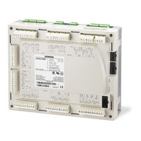
Siemens LMV52 series Basic Documentation (299 pages)
Burner Control with integrated Fuel / Air Ratio Control and Load Control, Load Control including O2 Trim Control for Forced Draft Burners
Brand: Siemens
|
Category: Control Unit
|
Size: 5.36 MB
Table of Contents
-
Lmv51.140B123
-
Lmv51.200A123
-
Lmv51.200A223
-
Lmv52.200A123
-
Lmv52.200A223
-
Lmv52.240A123
-
Lmv52.240A223
-
-
-
-
Qrb36
-
-
Flange X3-0337
-
X5-0338
-
Parameters44
-
-
-
-
General60
-
-
-
-
-
Displays97
-
-
Start Display103
-
Languages119
-
-
S / W Changeover119
-
Backup119
-
Type of Battery119
-
-
-
-
SLT Test121
-
-
Azl5121
-
-
-
-
Lmv52152
-
-
Manual Startup154
-
-
Note155
-
-
Loadlimits157
-
Shutdown157
-
-
Manual Startup159
-
-
Note159
-
-
Shutdown162
-
-
Technical Data
201-
Lmv5201
-
Basic Unit LMV5201
-
Lmv5202
-
Types of Cable202
-
-
-
-
General Data203
-
Mains Supply203
-
Undervoltage203
-
APS Test Valve203
-
-
-
Alarm Output204
-
Cable Lengths204
-
-
Advertisement
Siemens LMV52 series Manual (327 pages)
Brand: Siemens
|
Category: Computer Hardware
|
Size: 8.28 MB
Table of Contents
-
Safety Notes10
-
Warnings10
-
Life Cycle19
-
General20
-
X5-03 Pin 3)47
-
Parameters59
-
Prepurging66
-
Fuel Meter72
-
Program Stop96
-
General100
-
Setpoints (W)120
-
Port for the PC134
-
Modbus135
-
Menu Structure139
-
Languages163
-
TÜV Test165
-
Ebus PC Adapter224
-
Technical Data229
-
LMV5 and AZL5229
-
CAN Bus Cable233
-
Dimensions234
-
VSD Module238
-
VSD Module239
-
Inputs / Outputs239
-
Process Data247
-
Emc: Lmv5 - Vsd248
-
General251
-
Air Rate Change252
-
Lambda Factor253
-
Precontrol254
-
O2 Trim Control255
-
Startup257
-
O2 Alarm268
-
Self-Test271
-
O2 Sensor Test271
-
PLL52 O2 Module275
-
CAN Bus X84, X85278
-
Actuators / Vsds279
-
Setting Notes285
-
Other Notes287
-
Technical Data288
-
Dimensions302
-
Revision History303

Siemens LMV52 series Basic Documentation (278 pages)
Burner Control with integrated Fuel / Air Ratio Control, Burner Control with Load Control and Oxygen Trim Control for Forced-draft Burners
Brand: Siemens
|
Category: Control Unit
|
Size: 4.61 MB
Table of Contents
-
-
-
-
Flange X3-0335
-
X5-0335
-
Parameters41
-
-
-
General57
-
-
-
-
-
Displays94
-
-
Start Display101
-
Languages117
-
-
S / W Changeover117
-
Backup117
-
Type of Battery117
-
-
-
-
SLT Test119
-
-
Azl5119
-
Advertisement
Siemens LMV52 series Manual (39 pages)
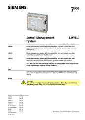
Burner Management System
Brand: Siemens
|
Category: Control Unit
|
Size: 1.28 MB
Siemens LMV52 series User Manual (17 pages)
Burner management system for forced draft
burners.
COx supervision and control
Brand: Siemens
|
Category: Control Unit
|
Size: 0.26 MB
Table of Contents
-
-
General5
-
Siemens LMV52 series Manual (29 pages)
Burner Management System
Brand: Siemens
|
Category: Control Systems
|
Size: 0.93 MB

Siemens LMV52 series User Documentation (10 pages)
Brand: Siemens
|
Category: Industrial Equipment
|
Size: 0.11 MB
Table of Contents
Advertisement