
Related Manuals for Bosch VG4-A-PSU0


Summary of Contents for Bosch VG4-A-PSU0
- Page 1 AutoDome Power Supply Boxes VG4-A-PSU0 | VG4-A-PSU1 | VG4-A-PSU2 Installation Guide...
-
Page 3: Table Of Contents
Mount the Power Supply Box 2.3.1 Attach Cover Door Route Wires and Attach Connectors 2.4.1 Methods for Routing Wires 2.4.2 Wiring the Power Supply Box 2.4.3 Power Supply Box Connections Bosch Security Systems, Inc. Installation Guide F.01U.250.895 | 1.0 | 2011.08... - Page 4 Controlling the AutoDome via the RS485 Protocol Fiber Optic Module with an RS232/RS422 Controller 3.5.1 Connecting to an LTC 4629 Head End Data/Video Transceiver 34 3.5.2 Configuring the VG5 AutoDome Audio Cables F.01U.250.895 | 1.0 | 2011.08 Installation Guide Bosch Security Systems, Inc.
-
Page 5: Important Safety Instructions
If not avoided, this could result in property damage or risk of damage to the unit. NOTICE! This symbol indicates information or a company policy that relates directly or indirectly to the safety of personnel or protection of property. Bosch Security Systems, Inc. Installation Guide F.01U.250.895 | 1.0 | 2011.08... -
Page 6: Important Safety Instructions
Power disconnect - Units have power supplied to the unit whenever the power cord is inserted into the power source. The power cord plug is the main power disconnect device for switching off the voltage for all units. F.01U.250.895 | 1.0 | 2011.08 Installation Guide Bosch Security Systems, Inc. - Page 7 – unit exhibits a distinct change in performance; – unit does not operate normally when the user correctly follows the operating instructions. Bosch Security Systems, Inc. Installation Guide F.01U.250.895 | 1.0 | 2011.08...
-
Page 8: Important Notices
12. Attachments, changes or modifications - Only use attachments/accessories specified by the manufacturer. Any change or modification of the equipment, not expressly approved by Bosch, could void the warranty or, in the case of an authorization agreement, authority to operate the equipment. - Page 9 Safety (power) ground is indicated by the symbol The system ground is only used to comply with safety standards or installation practices in certain countries. Bosch does not recommend connecting system ground to safety ground unless it is explicitly required. However, if the system ground and...
-
Page 10: Ul Certification
Bosch notices Video loss Video loss is inherent to digital video recording; therefore, Bosch Security Systems cannot be held liable for any damage that results from missing video information. To minimize the risk of lost digital information, Bosch Security Systems recommends multiple, redundant recording systems, and a procedure to back up all analog and digital information. - Page 11 AutoDome Power Supply Boxes Important Safety Instructions | en Copyright This manual is the intellectual property of Bosch Security Systems and is protected by copyright. All rights reserved. Trademarks All hardware and software product names used in this document are likely to be registered trademarks and must be treated accordingly.
-
Page 12: Installing The Power Supply Box
Verify that all the parts listed in the product's Parts List below are included. If any items are missing, notify your Bosch Security Systems Sales or Customer Service Representative. The original packing carton is the safest container in which to transport the unit and must be used if returning the unit for service. -
Page 13: Description
You must use water tight conduits and fittings to meet NEMA 4 standards. NOTICE! Power and I/O cabling must be routed separately inside different permanently earthed metal conduits. Bosch Security Systems, Inc. Installation Guide F.01U.250.895 | 1.0 | 2011.08... - Page 14 A readily accessible 2-pole disconnect device with a contact separation of at least 3 mm must be incorporated. Purchase the appropriate mounting hardware to use, depending on the location of power supply box. F.01U.250.895 | 1.0 | 2011.08 Installation Guide Bosch Security Systems, Inc.
-
Page 15: Mount The Power Supply Box
(not included). NOTICE! A stud diameter of 6.4 mm (1/4 in.) or 8 mm (5/16 in.), able to withstand a 120 kg (265 lb) pull-out force is recommended. Bosch Security Systems, Inc. Installation Guide F.01U.250.895 | 1.0 | 2011.08... -
Page 16: Attach Cover Door
Open the top hinge by pushing its pin lever outward and holding it open. Note: Both hinge pins must be fully compressed to open (unlock) the female hinges of the cover door before proceeding to the next step. F.01U.250.895 | 1.0 | 2011.08 Installation Guide Bosch Security Systems, Inc. - Page 17 After all wiring is complete, close the cover door and tighten the two (2) captive screws on the cover door to 10-12 N-m (90- 105 in.-lbs) to ensure the power supply box is watertight. Bosch Security Systems, Inc. Installation Guide F.01U.250.895 | 1.0 | 2011.08...
-
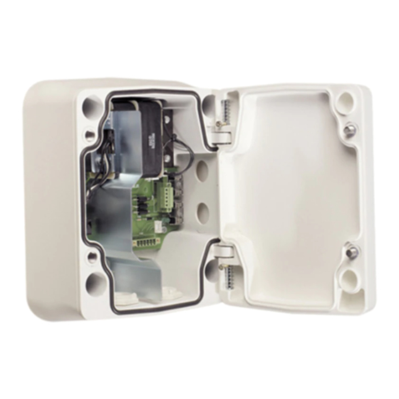
Page 18: Route Wires And Attach Connectors
(front) side of the power supply box and out to the AutoDome Arm Mount or to the Interface Board (for Pipe and Roof Parapet mounts). F.01U.250.895 | 1.0 | 2011.08 Installation Guide Bosch Security Systems, Inc. - Page 19 5 Coax, UTP Video, or Ethernet Wire Power In (Ethernet for VG5 700 Series only) 2 P101 Connector 6 Control Wire 3 Ground Connection 7 24 VAC Power Out 4 Transformer 8 P107 Connector Bosch Security Systems, Inc. Installation Guide F.01U.250.895 | 1.0 | 2011.08...
- Page 20 Earth Ground 24 VAC Power Out 24 VAC Power In (to AutoDome) P107 Connector 24 VAC Power In (to Heater) 24 VAC Power In (to Heater) AutoDome Power Heater Power F.01U.250.895 | 1.0 | 2011.08 Installation Guide Bosch Security Systems, Inc.
-
Page 21: Wiring The Power Supply Box
Table 2.1, Page 23. NOTICE! All video, control, and alarm wires either pass through the power supply box or by-pass it and connect directly to the Pipe Interface Board. Bosch Security Systems, Inc. Installation Guide F.01U.250.895 | 1.0 | 2011.08... -
Page 22: Power Supply Box Connections
T 5.0 A T 2.0 A T 3.15 A 115 V T 1.6 A T 2.0 A T 3.15 A 230 V T 0.8A T 2.0 A T 3.15 A F.01U.250.895 | 1.0 | 2011.08 Installation Guide Bosch Security Systems, Inc. - Page 23 Heater Heater to Dome Plug 24 VAC 24 VAC Ground (24 VAC) (24 VAC) 1. Applicable to VG5 100 and 600 Series AutoDomes only. Table 2.1 Power Box Connections Bosch Security Systems, Inc. Installation Guide F.01U.250.895 | 1.0 | 2011.08...
-
Page 24: Cable And Wire Standards
23 m (75 ft) Outdoor 1. Standard heater module. Add Add 16 W if using VG4-SHTR-XT kit. 2. Standard heater module. The VG4-SHTR-XT kit is not applicable to VG5 700 Series AutoDomes. F.01U.250.895 | 1.0 | 2011.08 Installation Guide Bosch Security Systems, Inc. -
Page 25: Video And Control Cables
Bilinx control data can also be sent over the same cable. Bilinx is a Bosch 2-way communication protocol that allows remote control, configuration, and updates over a video coax cable. Bilinx is available on all VG5 100 and 600 Series AutoDomes. -
Page 26: Using Utp To Transmit Video And Control
Bilinx control data can also be sent over the same two video wires (1 & 2). Bilinx is a Bosch 2-way communication protocol that allows remote control, configuration and updates over a passive UTP cable. -
Page 27: Using Ethernet To Transmit Video And Control
Maximum Distance 4 km (2.5 miles) Minimum Bandwidth 20 MHz (Video - 850 nm / Control - 1300 nm) Requirement Bosch LTC 4629 Fiber Receiver at controller end of system Terminal Connector Singlemode Fiber Type 9/125 µm, low loss single glass fiber... -
Page 28: Using A Fiber Optic Ethernet Media Converter To Transmit Video And Control
8–10/125 µm SMF. Must meet or exceed fiber standard ITU-T G.652. Maximum Distance 60 km (37.3 miles) Requirement Media converter receiver (CNFE2MC/IN) at controller end of system Terminal Duplex LC or Single SC Connection F.01U.250.895 | 1.0 | 2011.08 Installation Guide Bosch Security Systems, Inc. -
Page 29: Control-Only Cables
3.4.1 Controlling the AutoDome via Biphase (Shielded 2-wire, half-duplex, multi-drop, 5000 ft. cable limit) Biphase is the standard Bosch protocol used to send Pan/Tilt/ Zoom control over 2-wire shielded twisted pair (STP) terminated with a 100 Ω terminal resistor. The AutoDome has a 100 Ω termination resistor between the Biphase C+ and C- terminals. -
Page 30: Controlling The Autodome Via The Rs232 Protocol
50 ft. NOTICE! After making the wire connections for RS232 operation, reposition the slide switch located on the CPU Module to the camera head inward and away from the LEDs. F.01U.250.895 | 1.0 | 2011.08 Installation Guide Bosch Security Systems, Inc. - Page 31 Figure 3.5 Position of CPU Switch for RS232 Operation (camera module not shown for clarity) Switch Location LEDs RS232 CPU Module Note: To access the CPU switch you must remove the bubble from the pendant housing. Bosch Security Systems, Inc. Installation Guide F.01U.250.895 | 1.0 | 2011.08...
-
Page 32: Controlling The Autodome Via The Rs485 Protocol
LEDs (default). CAUTION! Bosch recommends that multiple RS485 connections be arranged as a connected series of point-to-point (multi- dropped) nodes, as a line or as a bus. It is not recommended to arrange RS485 connections as a star, ring, or as a multiple- connected network. - Page 33 Figure 3.7 Position of CPU Switch for RS485 Operation (camera module not shown for clarity) Switch Location LEDs RS485 CPU Module Note: To access the CPU switch you must remove the bubble from the pendant housing. Bosch Security Systems, Inc. Installation Guide F.01U.250.895 | 1.0 | 2011.08...
-
Page 34: Fiber Optic Module With An Rs232/Rs422 Controller
(RxD) wire enough to be able to connect these wires back into the P106 connector. Connect the blue (ground) wire to the C- pin on the P106 connector. F.01U.250.895 | 1.0 | 2011.08 Installation Guide Bosch Security Systems, Inc. - Page 35 Ensure that the protocol switch is in the left position for RS232 operation. Figure 3.9 Position of CPU Switch for RS232 Operation Switch Location LEDs Move Switch to the left for RS232 Operation CPU Module Bosch Security Systems, Inc. Installation Guide F.01U.250.895 | 1.0 | 2011.08...
-
Page 36: Audio Cables
22 AWG to Biphase connector (P105/P106) Shield Bare copper braid: 95% coverage Center conductor Stranded bare copper NOTICE! Separate the audio cables from the AC power lines to avoid noise. F.01U.250.895 | 1.0 | 2011.08 Installation Guide Bosch Security Systems, Inc. - Page 37 C+ (Biphase) P105/P106 Connector Earth Ground Audio Out Signal Ground NOTICE! Refer to the VG5 700 Series AutoDome User Manual for configuring and using audio over an IP Ethernet network. Bosch Security Systems, Inc. Installation Guide F.01U.250.895 | 1.0 | 2011.08...
- Page 38 | Cable and Wire Standards AutoDome Power Supply Boxes F.01U.250.895 | 1.0 | 2011.08 Installation Guide Bosch Security Systems, Inc.
- Page 40 Bosch Security Systems, Inc. 850 Greenfield Road Lancaster, PA 17601 U.S.A. www.boschsecurity.com © Bosch Security Systems, Inc., 2011...