Table of Contents
Advertisement
Advertisement
Table of Contents

Related Manuals for Bosch MIC Series


Summary of Contents for Bosch MIC Series
- Page 1 MIC Series Power Supplies MIC Series Installation Manual...
-
Page 3: Table Of Contents
Non-IR Power Supply Layout and Connections Fuse Ratings Installing a Non-IR Power Supply Optional Cards and Kits for Non-IR MIC Cameras Commissioning a MIC Series Camera with Public Address Speakers Commissioning a MIC Series Camera with Heater Option MIC IR Power Supply Units... -
Page 4: Safety
| Safety MIC Series Power Supplies Safety Important safety instructions Read, follow, and retain for future reference all of the following safety instructions. Heed all warnings on the unit and in the operating instructions before operating the unit. Cleaning - Unplug the unit from the outlet before cleaning. - Page 5 MIC Series Power Supplies Safety | en Power supply cord and plug protection - Protect the power supply cord and plug from foot traffic, being pinched by items placed upon or against them at electrical outlets, and its exit from the unit. For units intended to operate with 230 VAC, 50 Hz, the power supply cord must comply with the latest versions of IEC 60227.
-
Page 6: Safety Precautions
15. Attachments, changes or modifications - Only use attachments/accessories specified by the manufacturer. Any change or modification of the equipment, not expressly approved by Bosch, could void the warranty or, in the case of an authorization agreement, authority to operate the equipment. -
Page 7: Important Notices
MIC Series Power Supplies Safety | en Important notices Accessories - Do not place this unit on an unstable stand, tripod, bracket, or mount. The unit may fall, causing serious injury and/or serious damage to the unit. Use only with the cart, stand, tripod, bracket, or table specified by the manufacturer. - Page 8 | Safety MIC Series Power Supplies Disposal - Your Bosch product was developed and manufactured with high-quality material and components that can be recycled and reused. This symbol means that electronic and electrical appliances, which have reached the end of their working life, must be collected and disposed of separately from household waste material.
- Page 9 CCTV system. Video loss - Video loss is inherent to digital video recording; therefore, Bosch Security Systems cannot be held liable for any damage that results from missing video information. To minimize the risk of lost digital information, Bosch Security Systems recommends multiple, redundant recording systems, and a procedure to back up all analog and digital information.
- Page 10 | Safety MIC Series Power Supplies NOTICE! This is a class B product. In a domestic environment this product may cause radio interference, in which case the user may be required to take adequate measures. FCC & ICES Information...
- Page 11 MIC Series Power Supplies Safety | en INFORMATIONS FCC ET ICES Suite à différents tests, cet appareil s'est révélé conforme aux exigences imposées aux appareils numériques de classe B, en vertu de la section 15 du règlement de la Commission fédérale des communications des États-Unis (FCC), et en vertu de la...
- Page 12 LV Directive (73/23/EC) – RoHS (Restriction of Hazardous Substances) 2002/95/ ECEMC, CISPRA-B and CTIC Copyright This manual is the intellectual property of Bosch Security Systems and is protected by copyright. All rights reserved. F.01U.141.598 | 1.0 | 2009.11 Installation Manual...
- Page 13 The ongoing development of the products may mean that the content of the user guide can change without notice. Bosch Security Systems accepts no liability for damage resulting directly or indirectly from faults, incompleteness or discrepancies between the user guide and the product described.
-
Page 14: Customer Support And Service
| Safety MIC Series Power Supplies Customer Support and Service If this unit needs service, contact the nearest Bosch Security Systems Service Center for authorization to return and shipping instructions. Service Centers Repair Center- Telephone: 800-566-2283 Fax: 800-366-1329 E-mail: repair@us.bosch.com... - Page 15 MIC Series Power Supplies Safety | en Warranty and more information For additional information and warranty queries, please contact your Bosch Security Systems representative or visit our website at www.boschsecurity.com. Bosch Security Systems, Inc. Installation Manual F.01U.141.598 | 1.0 | 2009.11...
-
Page 16: Introduction
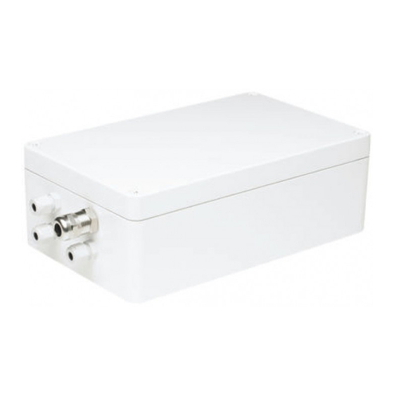
The MIC Series power supplies from Bosch Security Systems, Inc. provide all connections for power, telemetry and video for the MIC Series range of PTZ cameras. Each power supply has CE and FCC approval and is rated to IP65. The following table... -
Page 17: Preparing The Power Supply Unit
CAUTION! The PSU enclosures are not EXD rated and must be replaced with a certified enclosure if installed within a hazardous area. Please see the MIC Series EXD 440 Camera manual for further details. Bosch Security Systems, Inc. Installation Manual... -
Page 18: Securing The Power Supply Unit
| Introduction MIC Series Power Supplies Securing the Power Supply Unit Secure the power supply unit using four (4) M6 screws or bolts (not supplied); which secure through the holes in the enclosure as shown In the figure below. -
Page 19: Mic Shielded Composite Cable Gland Connection
MIC Series Power Supplies Introduction | en MIC Shielded Composite Cable Gland Connection The MIC power supplies are designed to use the MIC shielded composite cable. Fit this cable into the M16 nickel plated brass cable gland as detailed below. It is important that the braided cable screen engages with the internal clamps of the cable gland to ensure correct EMC protection. -
Page 20: Mic Non-Ir Power Supply Units
| MIC Non-IR Power Supply Units MIC Series Power Supplies MIC Non-IR Power Supply Units Use this chapter to install the following MIC power supply units: – MIC-240PSU-UL – MIC-115PSU-UL – MIC-24PSU-UL The MIC power supplies provide power, telemetry and video connections for a single MIC camera appropriate for the power supply type. - Page 21 MIC Series Power Supplies MIC Non-IR Power Supply Units | en to be connected to a central earth point. If fiber optics or other indirect connections are used to get data and video to and from the control room then the earth link should be left intact provided it is the only camera end earth reference point.
-
Page 22: Non-Ir Power Supply Layout And Connections
| MIC Non-IR Power Supply Units MIC Series Power Supplies Non-IR Power Supply Layout and Connections The following figure shows the power supply PCB connections: Figure 3.2 MIC-240PSU-UL layout Item PSU Head-end Description Head-end Terminal Head-end Power cable head-end... -
Page 23: Fuse Ratings
MIC Series Power Supplies MIC Non-IR Power Supply Units | en Fuse Ratings CAUTION! Replace with only the same type and rating of the fuse for continued protection against the risk of fire, damage or injury. The power supply houses four (4) off 20 mm fuses in fuse holders. -
Page 24: Installing A Non-Ir Power Supply
| MIC Non-IR Power Supply Units MIC Series Power Supplies Installing a Non-IR Power Supply DANGER! ELECTRICAL SHOCK HAZARD Ensure the power is disconnected prior to opening the power supply enclosure. Power must be disconnected before replacing any fuse in the MIC PSU. - Page 25 MIC Series Power Supplies MIC Non-IR Power Supply Units | en Figure 3.3 High voltage input head-end shield fitted inside the PSU enclosure If using a conduit for the power cord, remove the blanking plug and install a suitable conduit in its place. Secure as recommended by the conduit manufacturer.
- Page 26 | MIC Non-IR Power Supply Units MIC Series Power Supplies Carefully connect the Live and Neutral cores to the correct HD1 screw terminals as shown below and also printed on the PCB (next to the connector and not visible in the image above).
- Page 27 MIC Series Power Supplies MIC Non-IR Power Supply Units | en Composite Cable Function MIC PSU PCB Marking Wire Color Terminal Block AC supply HD3-1 Power Green AC supply return HD3-2 Power White RX + HD3-3 Yellow Rx - HD3-4...
- Page 28 | MIC Non-IR Power Supply Units MIC Series Power Supplies 10. Connect a tamper switch relay to HD2, if necessary. 11. Feed the coax cable through the cable gland and crimp the end with a BNC connector then connect the coax video cable to the CN1 head-end.
-
Page 29: Optional Cards And Kits For Non-Ir Mic Cameras
Commissioning a MIC Series Camera with Public Address Speakers The MIC Series Public Address camera has two (2) 6 W, 8 Ohm, IP67 rated speakers connected in series to allow for public address (PA) applications. These use the brown and gray wires on the composite cable that are normally used for IR illuminators or heaters. -
Page 30: Commissioning A Mic Series Camera With Heater Option
Feed the speaker cable through one of the conduit glands in the power supply unit enclosure. Connect the speaker cable from a third party amplifier and microphone. Commissioning a MIC Series Camera with Heater Option These instructions are applicable to the MIC non-IR power supplies only. - Page 31 HD6-2 Heater IR Lamps 1. See Section 3.7 Commissioning a MIC Series Camera with Heater Option, page 30, for details on commissioning MIC cameras with the heater option fitted. 2. IR power supplies only; see Section 4 MIC IR Power Supply Units, page 32, for more details.
-
Page 32: Mic Ir Power Supply Units
– MIC-IR-115PSU-UL – MIC-IR-24PSU-UL The power supplies for the MIC Series IR cameras are available in 230/115 VAC source and 24 VAC source versions. DANGER! ELECTRICAL SHOCK HAZARD Ensure the power is disconnected prior to opening the power supply enclosure. -
Page 33: Printed Circuit Board Earth Link
MIC Series Power Supplies MIC IR Power Supply Units | en HD2 head-end provides the option for connection up to four (4) alarm inputs to the power supply. These can be tamper switches or inputs from other sensors or switches. -
Page 34: Fuse Ratings
| MIC IR Power Supply Units MIC Series Power Supplies Fuse Ratings CAUTION! Replace with only the same type and rating of the fuse for continued protection against the risk of fire, damage or injury. There are five (5) 20 mm fuses fitted to the power supply with... -
Page 35: Mic Ir Power Supply Layout And Connections
MIC Series Power Supplies MIC IR Power Supply Units | en MIC IR Power Supply Layout and Connections Figure 4.2 MIC-IR-240PSU layout Item PSU Head-end Description Head-end Terminal Head-end Power cable head-end Screw terminal 4-input alarm head-end Screw terminal Composite cable head-end Screw terminal... -
Page 36: Installing A Mic Ir Power Supply
| MIC IR Power Supply Units MIC Series Power Supplies Installing a MIC IR Power Supply DANGER! ELECTRICAL SHOCK HAZARD Ensure the power is disconnected prior to opening the power supply enclosure. Power must be disconnected before replacing any fuse in the MIC PSU. - Page 37 MIC Series Power Supplies MIC IR Power Supply Units | en Figure 4.3 High voltage input head-end shield fitted inside the PSU enclosure If using a conduit for the power cord, remove the blanking plug and install a suitable conduit in its place, secure as recommended by the conduit manufacturer.
- Page 38 | MIC IR Power Supply Units MIC Series Power Supplies Figure 4.4 Mains cable wired into HD1 showing earth terminal con- nections Enclosure lid earth cable Earth core from power supply PCB Earth core from Mains cable Enclosure earth termination post Feed the remaining video and telemetry cables through the appropriate sized glands.
- Page 39 MIC Series Power Supplies MIC IR Power Supply Units | en NOTICE! The earth core 6 mm ring crimp should be a Tyco Electronics, 0- 0321045-0, PIDG, M6, BLUE, UL certification CCN ZMVV, file E13288. A suitable ring crimp tool for fitting the ring crimp is a Davico type DHCR15 or equivalents.
- Page 40 | MIC IR Power Supply Units MIC Series Power Supplies 13. Crimp or screw telemetry connections to head-ends HD4 and HD5 to connect the MIC camera to the control room as shown below. Telemetry Signal Name RxB or Rx -...
- Page 41 MIC Series Power Supplies MIC IR Power Supply Units | en Figure 4.6 MIC Series IR power supply LED positions LED 1 and Indicates that 18 VAC is available from the LED 2 power supply and that the supply fuses are intact.
-
Page 42: Commissioning The Ir Lamps
Multi Alarm mode on. LED 6 (refer to Figure 4.6), called STATUS starts flashing indicating correct operation. Activating the IR Lamps command in the MIC Series Universal Camera Setup Software (Cam-set) activates the twin IR lamps and illuminates LED 5. -
Page 43: Technical Specifications
MIC Series Power Supplies Technical Specifications | en Technical Specifications The MIC power supplies are fitted into a cast aluminium IP65 rated enclosure with the following specifications: MIC PSU Voltage Power Output MIC-240PSU-UL 230 VAC 50/60 Hz 40 VA 18 VAC... -
Page 44: Dimensional Drawings
| Technical Specifications MIC Series Power Supplies Dimensional Drawings 288 mm (11.3 in.) 260 mm (10.2 in.) 240 mm (9.5 in.) F.01U.141.598 | 1.0 | 2009.11 Installation Manual Bosch Security Systems, Inc. - Page 46 Bosch Security Systems, Inc. www.boschsecurity.com © Bosch Security Systems, Inc., 2009...