Table of Contents
Advertisement
Quick Links
Advertisement
Table of Contents

Related Manuals for Bosch VJC-7000-90


Summary of Contents for Bosch VJC-7000-90
- Page 1 VIDEOJET connect 7000 VJC-7000-90 Operation Manual...
-
Page 3: Table Of Contents
System Requirements Configuration Overview General settings Identification 7.1.1 Naming 7.1.2 7.1.3 iSCSI Initiator extension Password 7.2.1 Enter Password 7.2.2 Confirm password Date/Time 7.3.1 Date format 7.3.2 Device date / Device time Bosch Security Systems Operation Manual 2014.10 | 1.4 | F.01U.291.524... - Page 4 Storage Management 10.1.1 Device manager 10.1.2 Recording media 10.1.3 Activating and configuring storage media 10.1.4 Formatting storage media 10.1.5 Deactivating storage media 10.2 Remote Video Device 10.2.1 Status 10.2.2 Last error 2014.10 | 1.4 | F.01U.291.524 Operation Manual Bosch Security Systems...
- Page 5 12.4.1 SNMP 12.4.2 UPnP 12.4.3 Quality of Service 12.5 Accounts 12.6 IPv4 Filter 12.7 Encryption Service 13.1 Installer Menu 13.1.1 Reboot device 13.1.2 Factory defaults 13.2 Maintenance 13.2.1 Update server Bosch Security Systems Operation Manual 2014.10 | 1.4 | F.01U.291.524...
- Page 6 Configure VIDEOJET connect 7000 to Operate with a MIC7000 Camera 15.1 Configure Alarm Inputs and Outputs 15.2 Configure Audio 15.3 Configure Video Playback Troubleshooting and Maintenance 16.1 Troubleshooting 16.2 Maintenance Technical data 2014.10 | 1.4 | F.01U.291.524 Operation Manual Bosch Security Systems...
-
Page 7: Safety
Legal Information Copyright This manual is the intellectual property of Bosch Security Systems, Inc. and is protected by copyright. All rights reserved. Trademarks All hardware and software product names used in this document are likely to be registered trademarks and must be treated accordingly. -
Page 8: Important Safety Instructions
Important Safety Instructions Attachments - Use only attachments/accessories specified by the manufacturer. Any change or modification of the equipment, not expressly approved by Bosch, could void the user's warranty or authorization agreement. Cleaning - Unplug the device before cleaning. Generally, using a dry cloth for cleaning is sufficient, but a moist, fluff-free cloth may also be used. - Page 9 Warning! Short-circuit (overcurrent) protection device required This product relies on the building's installation for short-circuit (overcurrent) protection. Ensure that the protective device is Listed rated not greater than: 20 A. Bosch Security Systems Operation Manual 2014.10 | 1.4 | F.01U.291.524...
-
Page 10: Important Notices
60950-1 . UL Certification does not cover the performance or reliability of the security or signaling aspects of this product. UL MAKES NO REPRESENTATIONS, WARRANTIES, OR CERTIFICATIONS WHATSOEVER REGARDING THE PERFORMANCE OR RELIABILITY OF ANY SECURITY OR SIGNALING-RELATED FUNCTIONS OF THIS PRODUCT. 2014.10 | 1.4 | F.01U.291.524 Operation Manual Bosch Security Systems... -
Page 11: Customer Support And Service
VIDEOJET connect 7000 Safety | en Customer Support and Service If this unit needs service, contact the nearest Bosch Security Systems Service Center for authorization to return and shipping instructions. Service Centers Telephone: 800-366-2283 or 585-340-4162 Fax: 800-366-1329 Email: cctv.repair@us.bosch.com... -
Page 12: Unpacking
Verify that all the parts listed in the Parts List below are included. If any items are missing, notify your Bosch Security Systems Sales or Customer Service Representative. – Do not use this product if any component appears to be damaged. Please contact Bosch Security Systems in the event of damaged goods. –... -
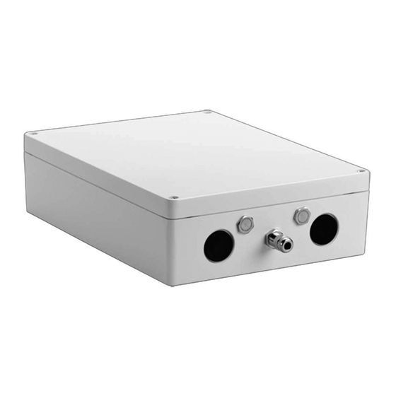
Page 13: Product Overview
The device VIDEOJET connect 7000 (VJC-7000-90) is a full-featured network power supply unit that can operate a variety of Bosch PTZ cameras such as MIC7000. The device includes one (1) HPoE network connection, two (2) standard network interfaces for connections to... -
Page 14: Typical Configuration - Basic
Cat5e/Cat6e = 100 m max. Figure 3.1: Basic configuration with VIDEOJET connect 7000 1 Ethernet (network) cable (Cat5e/Cat6e) (user-supplied) between a Bosch camera and the port labeled PoE on VIDEOJET connect 7000 2 Data-only IP cable (Cat5e/Cat6e) to the head-end network Note: The cable to the head-end also can be fiber optic cable from one of the two SFP slots. -
Page 15: Typical Configuration - Daisy Chain
Cat5e/Cat6e = 100 m max. Figure 3.2: Typical daisy chain configuration for VIDEOJET connect 7000 Ethernet (network) cable (Cat5e/Cat6e) (user-supplied) between a Bosch camera and the port labeled PoE on VIDEOJET connect 7000 Data-only IP cable (Cat5e/Cat6e) to the head-end network Note: The cable to the head-end also can be fiber optic cable from one of the two SFP slots. -
Page 16: Typical Configuration - Multiple Cameras To Head-End Network
1 Ethernet (network) cable (Cat5e/Cat6e) (user-supplied) between a Bosch camera and the port labeled PoE on VIDEOJET connect 7000 2 Data-only IP cable (Cat5e/Cat6e) between a Bosch IP camera and the port labeled ETH 2 on VIDEOJET connect 7000 3 Head-end network... -
Page 17: Typical Configuration - Mobile Viewing
Cat5e/Cat6e = 100 m max. Figure 3.4: Mobile Viewing using the integrated Transcoder of VIDEOJET connect 7000 1 Ethernet (network) cable (Cat5e/Cat6e) (user-supplied) between a Bosch camera and the port labeled PoE on VIDEOJET connect 7000 2 Network switch (user-supplied) 3 Head-end network 4 Internet (“the cloud”) -
Page 18: Technical Data
SFP (small form-factor pluggable) Two (2) slots for use with SFP-based fiber optic modules (1GB only) as recommended in the section Optional Accessories, page 12 Ingress Protection Rating/ IP66, IP67, Type 4 Standard 2014.10 | 1.4 | F.01U.291.524 Operation Manual Bosch Security Systems... -
Page 19: Dimensional Drawing
VIDEOJET connect 7000 Technical Data | en Dimensional Drawing Bosch Security Systems Operation Manual 2014.10 | 1.4 | F.01U.291.524... -
Page 20: Installation
Electrical Code (NEC)), Canadian Electrical Code, Part I (also called CE Code or CSA C22.1), ® and all applicable local codes. Bosch Security Systems, Inc. accepts no liability for any damages or losses caused by incorrect or improper installation. Warning! - Page 21 If you are securing the enclosure in a vertical position (for example, on a wall), one person should hold the enclosure lid while another person secures the enclosure body in place, to avoid damage to any part of the enclosure, and/or injury to the installers. Bosch Security Systems Operation Manual 2014.10 | 1.4 | F.01U.291.524...
-
Page 22: Conduit Installation
Optional hole (size M25 / ¾”), plugged, for conduit (user-supplied) for HPoE Ethernet (network) cable (Cat5e/Cat6e, user-supplied) to IP camera – Secure the conduit as recommended by the conduit manufacturer. 2014.10 | 1.4 | F.01U.291.524 Operation Manual Bosch Security Systems... -
Page 23: Pcba Connections
Two (2) slots for use with SFP-based fiber optic modules (1GB only) (user-supplied) Two (2) RJ45 Ethernet (female) ports (labeled ETH1, ETH2) One (1) RJ45 HPoE Ethernet (female) port (labeled PoE) Note: The protective material over the PCBA is not shown. Bosch Security Systems Operation Manual 2014.10 | 1.4 | F.01U.291.524... -
Page 24: Power Cable Installation
Feed fiber optic cable from the external device through an appropriate cable gland or conduit hole near the SFP socket(s). – Terminate the cable. – Connect the cable to the appropriate SFP socket(s). 2014.10 | 1.4 | F.01U.291.524 Operation Manual Bosch Security Systems... -
Page 25: Alarm Inputs
Check that the connections are secure. – Carefully press the connector to the appropriate location on the PCBA. Washer Pump 11. Connect the washer pump drive, if applicable. – Prepare the cable as needed. Bosch Security Systems Operation Manual 2014.10 | 1.4 | F.01U.291.524... -
Page 26: Audio In And Out
13. Install a CF card to save recordings locally, if applicable. Caution! Bosch recommends disconnecting power to the unit whenever inserting or removing a CF card. Carefully slide a CF card into the card slot (item 9) as far as it will go until it locks into place. -
Page 27: Control Of Connected Devices
You can find notes on using Microsoft Internet Explorer in the online Help in Internet Explorer. If you choose to use a computer running Microsoft Internet Explorer or any of the Bosch software, the computer must conform to the following minimum requirements: –... -
Page 28: Configuration Overview
The LIVE page is used to display the live video stream and control the unit. The PLAYBACK page is used for playing back recorded sequences. The SETTINGS page is used to configure the unit and the application interface. 2014.10 | 1.4 | F.01U.291.524 Operation Manual Bosch Security Systems... -
Page 29: General Settings
– live is the lowest authorization level. At this level you can only view the live video image and switch between the different live image displays. Bosch Security Systems Operation Manual 2014.10 | 1.4 | F.01U.291.524... -
Page 30: Enter Password
If there are empty lines at the bottom of the table, for example after deletions, add new data by marking the row and selecting values from the list boxes. When finished, click OK to save and activate the table. 2014.10 | 1.4 | F.01U.291.524 Operation Manual Bosch Security Systems... -
Page 31: Time Server Ip Address
SNTP server protocol. This protocol provides high accuracy and is required for special applications and future function extensions. Select Time server if the server uses the RFC 868 protocol. Bosch Security Systems Operation Manual 2014.10 | 1.4 | F.01U.291.524... -
Page 32: Web Interface
Select the check boxes for the functions to be displayed on the LIVE. The selected elements are checked. Check to see if the desired items are shown. 2014.10 | 1.4 | F.01U.291.524 Operation Manual Bosch Security Systems... -
Page 33: Transmit Audio
File for system log Enter the path for saving the system log. If necessary, click Browse... to find a suitable folder. Bosch Security Systems Operation Manual 2014.10 | 1.4 | F.01U.291.524... -
Page 34: Transcoder
If your router has UPnP enabled, click Configure Router to save the settings to the router. Otherwise, configure your router manually. The cameras are now available for selection on the PLAYBACK page. Transcoding will only be possible once recordings for the cameras are available. 2014.10 | 1.4 | F.01U.291.524 Operation Manual Bosch Security Systems... -
Page 35: Transcoder Profile
The value entered here must be at least 10% higher than the value entered in the Target bit rate field. If the value entered here is too low, it is automatically adjusted. Bosch Security Systems Operation Manual 2014.10 | 1.4 | F.01U.291.524... -
Page 36: Transcoding Interval
The image quality is retained even in the case of increased movement since the bandwidth is then filled up to the value that is entered under Maximum bit rate. 2014.10 | 1.4 | F.01U.291.524 Operation Manual Bosch Security Systems... -
Page 37: Audio
VIDEOJET connect 7000 Transcoder | en Audio Input volume You can set the input volume with the slider (from 0 to 31, with 0 as the default). Bosch Security Systems Operation Manual 2014.10 | 1.4 | F.01U.291.524... -
Page 38: Recording
A Video Recording Manager (VRM) can control all recording when accessing an iSCSI system. The VRM is an external program for configuring recording tasks for video servers. For further information, contact your local customer service at Bosch Security Systems. 10.1 Storage Management 10.1.1... -
Page 39: Activating And Configuring Storage Media
This field identifies when the last error occurred on the remote video device. 10.2.3 Recording target This field identifies the recording target for the respective camera. This target is also the source for the recordings available on the PLAYBACK page. Bosch Security Systems Operation Manual 2014.10 | 1.4 | F.01U.291.524... -
Page 40: Bit Rate
PLAYBACK page. 10.2.6 Start Recording Click this button to start the recording for a camera. 10.2.7 Stop Recording Click this button to stop the recording for a camera. 2014.10 | 1.4 | F.01U.291.524 Operation Manual Bosch Security Systems... -
Page 41: Alarm
When finished, click Set to transmit the scripts to the device. If the transfer was successful, the message Script successfully parsed. is displayed over the text field. If it was not successful, an error message is displayed with further information. Bosch Security Systems Operation Manual 2014.10 | 1.4 | F.01U.291.524... -
Page 42: Network
If the device is used behind a firewall, TCP (Port 80) should be selected as the transmission protocol. For use in a local network, choose UDP. Multicast operation is only possible with the UDP protocol. The TCP protocol does not support multicast connections. 2014.10 | 1.4 | F.01U.291.524 Operation Manual Bosch Security Systems... -
Page 43: Http Browser Port
100 Mbps HD (half duplex) – 100 Mbps FD (full duplex) Note: Do not select a baud rate for this port unless a device is connected to this port on VIDEOJET connect 7000. Bosch Security Systems Operation Manual 2014.10 | 1.4 | F.01U.291.524... -
Page 44: Network Mss [Byte]
Select your dynamic DNS Provider from the drop-down list. 12.2.3 Host name Enter the host name registered for the unit. 12.2.4 User name Enter the user name you registered. 12.2.5 Password Enter the password you registered. 2014.10 | 1.4 | F.01U.291.524 Operation Manual Bosch Security Systems... -
Page 45: Force Registration Now
12.3 Advanced 12.3.1 Cloud-based Services The Scene Mode determines how the camera communicates with Bosch Cloud-based Security and Services. For more information about these services and their availability, visit: http://cloud.boschsecurity.com – Select Auto to allow the camera to poll the server a few times; if no contact is made, it stops polling. -
Page 46: Upnp
If either of these ranges are set, no IP V6 addresses are allowed to actively connect to the device. The device itself may initiate a connection (for example, to send an alarm) outside the defined ranges if it is configured to do so. 2014.10 | 1.4 | F.01U.291.524 Operation Manual Bosch Security Systems... -
Page 47: Encryption
VIDEOJET connect 7000 Network | en 12.7 Encryption If an encryption license is installed, this submenu gives access to the encryption parameters. Bosch Security Systems Operation Manual 2014.10 | 1.4 | F.01U.291.524... -
Page 48: Service
Thus, a camera can be serviced and updated remotely without requiring a technician to make changes to the device on site. The latest firmware can be obtained from your customer service center or from the Bosch Security Systems download area. -
Page 49: Upload History
This window is for information only and cannot be modified. Keep this information at hand when seeking technical support. Select the text on this page with a mouse and copy it so that it can be pasted into an e-mail if required. Bosch Security Systems Operation Manual 2014.10 | 1.4 | F.01U.291.524... -
Page 50: Operation Via The Browser
When accessing the unit with a browser, the local storage, processor and network status icons are shown in the upper right of the window next to the Bosch logo. When a local storage card is available, the memory card icon changes color (green, orange or red) to indicate the local storage activity. -
Page 51: Status Icons
(With VRM recording this option is not active.) A collapsible panel on the left of the display has four tabs: Bosch Security Systems Operation Manual 2014.10 | 1.4 | F.01U.291.524... -
Page 52: Selecting Recordings For Playback
The time bar below the video image allows quick orientation. The time interval associated with the sequence is displayed in the bar in gray. A green arrow above the bar indicates the position of the image currently being played back within the sequence. 2014.10 | 1.4 | F.01U.291.524 Operation Manual Bosch Security Systems... - Page 53 Jump to the following bookmark Bookmarks are only valid while in the Recordings page; they are not saved with the sequences. All bookmarks are deleted when you leave the page. Bosch Security Systems Operation Manual 2014.10 | 1.4 | F.01U.291.524...
-
Page 54: Configure Videojet Connect 7000 To Operate With A Mic7000 Camera
Counter) appears only in the configuration menu of the camera “bound” to VIDEOJET connect 7000. 15.3 Configure Video Playback To configure video playback with VIDEOJET connect 7000, first you must map the device to record. See Recording, page 38 for details. 2014.10 | 1.4 | F.01U.291.524 Operation Manual Bosch Security Systems... -
Page 55: Troubleshooting And Maintenance
- an object has fallen on the device; - the device has been dropped, or its enclosure has been damaged; - the device does not operate normally when the user follows the operating instructions correctly. Bosch Security Systems Operation Manual 2014.10 | 1.4 | F.01U.291.524... - Page 56 | Troubleshooting and Maintenance VIDEOJET connect 7000 Servicing - Do not attempt to service this device yourself. Refer all servicing to qualified service personnel. 2014.10 | 1.4 | F.01U.291.524 Operation Manual Bosch Security Systems...
-
Page 57: Technical Data
VIDEOJET connect 7000 Technical data | en Technical data For more specific product details, see the VIDEOJET connect 7000 datasheet. Bosch Security Systems Operation Manual 2014.10 | 1.4 | F.01U.291.524... - Page 60 Bosch Security Systems, Inc. Bosch Sicherheitssysteme GmbH 850 Greenfield Road Robert-Bosch-Ring 5 Lancaster, PA, 17601 85630 Grasbrunn Germany www.boschsecurity.com © Bosch Security Systems, Inc., 2014...