Table of Contents
Advertisement
Quick Links
SERVICE MANUAL
LekSound.net
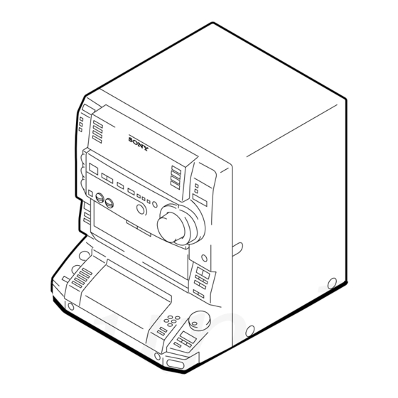
HCD-LV60 is the Amplifier, VCD/CD player,
Tape Deck and Tuner section in LBT-LV60.
Dolby noise reduction manufactured under license
from Dolby Laboratories Licensing Corporation.
"DOLBY" and the double-D symbol ; are trade-
marks of Dolby Laboratories Licensing Corporation.
LekSound.net
LekSound.net
HCD-LV60
Model Name Using Similar Mechanism
CD Mechanism Type
CD
Section
Base Unit Name
Optical Pick-up Name
Model Name Using Similar Mechanism
TAPE
Section
Tape Transport Mechanism Type
SPECIFICATIONS
COMPACT Hi-Fi STEREO SYSTEM
E Model
HCD-VR50/VR70
CDM37L-5BD34L
BU-5BD34L
KSS-213D/Q-NP
NEW
TCM-230PWR12
– Continued on next page –
Advertisement
Table of Contents

Related Manuals for Sony HCD-LV60


Summary of Contents for Sony HCD-LV60
- Page 1 HCD-LV60 SERVICE MANUAL E Model LekSound.net HCD-LV60 is the Amplifier, VCD/CD player, Tape Deck and Tuner section in LBT-LV60. Dolby noise reduction manufactured under license Model Name Using Similar Mechanism HCD-VR50/VR70 from Dolby Laboratories Licensing Corporation. CD Mechanism Type CDM37L-5BD34L “DOLBY”...
-
Page 2: Table Of Contents
LINE WITH MARK 0 ON THE SCHEMATIC DIAGRAMS AND IN THE PARTS LIST ARE CRITICAL TO SAFE ELECTRICAL PARTS LIST OPERATION. REPLACE THESE COMPONENTS WITH ....... 71 SONY PARTS WHOSE PART NUMBERS APPEAR AS SHOWN IN THIS MANUAL OR IN SUPPLEMENTS PUB- LISHED BY SONY. -
Page 3: Servicing Notes
SECTION 1 SERVICING NOTES SELF-DIAGNOSIS NOTES ON HANDLING THE OPTICAL PICK-UP This unit is equipped with a self-diagnosis function. BLOCK OR BASE UNIT The function is used for diagnosing the conditions of the circuits The laser diode in the optical pick-up block may suffer electro- of the VIDEO board. -
Page 4: General
SECTION 2 GENERAL LOCATION OF CONTROLS – Front Panel – 2 3 4 5 1 ?/1 (POWER) button DECK A operating button 2 DAILY button eh x button 3 REC button m button 4 SLEEP button M button 5 c/CLOCK SET button ej g button 6 DISPLAY G button... - Page 5 – Rear Panel – 1 ANTENNA terminal 2 VOLTAGE SELECTOR switch 3 S VIDEO OUT jack 4 SYSTEM SELECT switch 5 CD DIGITAL OUT terminal 6 FRONT SPEAKER terminal 7 VIDEO OUT jack 8 VIDEO 1 jack 9 MD IN/OUT jack q;...
-
Page 6: Disassembly
SECTION 3 DISASSEMBLY Note: Follow the disassembly procedure in the numerical order given. CASE 2 five screws (BVTT3 × 6) 6 case LekSound.net 1 three screws (CASE3 TP2) 3 two screws (BVTP3 × 8) LekSound.net 1 three screws (CASE3 TP2) FRONT PANEL SECTION 1 wire (flat type) (15 core) (CN303) - Page 7 TAPE MECHANISM DECK (TCM-230PWR12) 2 two screws (BVTP3 × 8) 1 wire (flat type) (17 core) (CN1001) 1 wire (flat type) (15 core) (CN601) LekSound.net 2 two screws (BVTP3 × 8) 3 tape mechanism deck (TCM-230PWR12) LekSound.net MAIN BOARD 5 back panel 1 wire (flat type) (13 core) (CN441) 2 nine screws...
- Page 8 CD MECHANISM DECK (CDM37L-5BD34L) 1 wire (flat type) (13 core) (CN411) 2 connector (CN701) 3 three screws 3 three screws (BVTP3 × 8) (BVTP3 × 8) LekSound.net 5 Open the cable clamp. 2 connector (CN412) 3 two screws (BVTP3 × 8) LekSound.net 7 five screws (BVTP3 ×...
- Page 9 BASE UNIT (BU-5BD34L) LekSound.net 3 base unit (BU-5BD34L) 2 boss 1 BU fitting screw LekSound.net DISC TABLE Note: When the disc table is installed, adjust the positions of roller cam and mark B as shown in the figure, then set to the groove of disc table.
-
Page 10: Test Mode
SECTION 4 TEST MODE [MC Cold Reset] [CD Delivery Mode] • The cold reset clears all data including preset data stored in the • This mode moves the optical pick-up to the position durable to RAM to initial conditions. Execute this mode when returning vibration. - Page 11 [Aging Mode] 2. Tape Deck Section This mode can be used for operation check of tape deck section. • The sequence during the aging mode is following as below. Tape deck section work in parallel. • If an error occurred, stop display that step. •...
-
Page 12: Mechanical Adjustments
SECTION 5 SECTION 6 MECHANICAL ADJUSTMENTS ELECTRICAL ADJUSTMENTS Precaution DECK SECTION 0 dB = 0.775 V 1. Clean the following parts with a denatured alcohol-moistened swab: Precaution record/playback heads pinch rollers 1. Demagnetize the record/playback head with a head demagne- erase head rubber belts tizer. - Page 13 Record/Playback Head Azimuth Adjustment Adjustment Location: Playback Head (Deck A). Record/Playback/Erase Head (Deck B). DECK A DECK B Note: Perform this adjustments for both decks Procedure: 1. Mode: Playback (FWD) test tape MAIN board P-4-A100 MD OUT jack (J701) (10 kHz, – 10 dB) L-CH, R-CH level meter forward...
- Page 14 Specification values: DECK B REC Bias Adjustment J101 PB level: 47.2 to 53.0 mV (– 24.3 to – 23.3 dB) Procedure: 1. Mode: Record Adjustment Location: MAIN board FUNCTION: VIDEO MAIN board – MAIN BOARD (Conductor Side) – VIDEO 1 AUDIO IN jack (J701) L-CH, R-CH ...
-
Page 15: Cd Section
E-F Balance (1 Track Jump) Check CD SECTION VIDEO SECTION oscilloscope Note: Frequency Adjustment (DC range) 1. CD Block is basically designed to operate without adjustment. There- Connection: fore, check each item in order given. BD board 2. Use YEDS-18 disc (3-702-101-01) unless otherwise indicated. frequency counter TP (TE) 3. -
Page 16: Diagrams
HCD-LV60 SECTION 7 DIAGRAMS 7-1. BLOCK DIAGRAM – CD SERVO Section – CTL2 CTL1 FILTER XTSL DIGITAL SIGNAL PROCESSOR RF AMP, IC101 (1/2) FOCUS/TRACKING ERROR AMP 53 55 52 54 XTAO IC103 DETECTOR CD A+5V MCLK CLOCK 33.8MHz XTAI GENERATOR... -
Page 17: Block Diagram - Audio/Video Cd Section
HCD-LV60 7-2. BLOCK DIAGRAM – AUDIO/VIDEO CD Section – DIGITAL FILTER, D/A CONVERTER IC509 MCLK 33.8MHz (Page 16) MPEG VIDEO/AUDIO DECODER, DIGITAL DA-DATA DATA VOUTL CD-L (Page 19) VIDEO SIGNAL PROCESSOR MPEG INPUT FILTER, LOW-PASS AUDIO DA-BCK LOW-PASS IC505 AUDIO... -
Page 18: Block Diagram - Tape Deck Section
HCD-LV60 7-3. BLOCK DIAGRAM – TAPE DECK Section – DECK PROCESS DECK A/B SELECT, PB/REC EQ AMP, DOLBY NR AMP, ALC, AMS IC301 • SIGNAL PATH : PLAYBACK (DECK A) DOLBY PASS HP101 (PLAYBACK) : PLAYBACK (DECK B) PB OUT (L) -
Page 19: Block Diagram - Main Section
HCD-LV60 7-4. BLOCK DIAGRAM – MAIN Section – RV750 DIGITAL ECHO ECHO REC-L IC851 LEVEL (Page 18) J802 SPEANA MIC AMP MIC AMP (Page 20) MIC 2 IC850 (1/2) IC850 (2/2) RV751 MIC LEVEL MD OUT J801 MIC 1 R-CH... -
Page 20: Block Diagram - Display/Key Control Power Supply Section
HCD-LV60 7-5. BLOCK DIAGRAM – DISPLAY/KEY CONTROL POWER SUPPLY Section – (Page 19) (Page 19) FLUORESCENT INDICATOR TUBE DRIVER, BAND-PASS FILTER KEY CONTROL IC603 IC601 BPF0 LINE BPF1 BPF2 B.P.F. BPF3 BPF4 POWER TRANSFORMER LekSound.net T951 REC IN GRID DRIVE... -
Page 21: Note For Printed Wiring Boards And Schematic Diagrams
7-6. NOTE FOR PRINTED WIRING BOARDS AND SCHEMATIC DIAGRAMS • Circuit Boards Location (In addition to this, the necessary note is printed in each block) TRANS board Note on Printed Wiring Board: Note on Schematic Diagram: • X : parts extracted from the component side. •... -
Page 22: Printed Wiring Board - Bd Board
HCD-LV60 7-7. PRINTED WIRING BOARD – BD Board – • See page 21 for Circuit Boards Location. LekSound.net LekSound.net (Page 26) LekSound.net (KSS-213D/Q-NP) • Semiconductor • Semiconductor Location Location (Side A) (Side B) Ref. No. Location Ref. No. Location Q101... -
Page 23: Schematic Diagram - Bd Board
HCD-LV60 7-8. SCHEMATIC DIAGRAM – BD Board – • See page 37 for Waveforms. • See page 50 for IC Block Diagrams. LekSound.net LekSound.net (Page 24) LekSound.net OSC BUFFER • Voltages and waveforms are dc with respect to ground under no-signal conditions. -
Page 24: Schematic Diagram - Video Board (1/2)
HCD-LV60 7-9. SCHEMATIC DIAGRAM – VIDEO Board (1/2) – • See page 27 for Waveforms. • See page 50 for IC Block Diagrams. LekSound.net (Page 23) BUS XRD LekSound.net C471 NJM2267M LekSound.net C472 (Page 35) R337 4.7k 5.6k (Page 34) (Page 25) •... - Page 25 HCD-LV60 7-10. SCHEMATIC DIAGRAM – VIDEO Board (2/2) – • See page 27 for Waveforms. • See page 50 for IC Block Diagrams. (Page 24) LekSound.net LekSound.net LekSound.net • Voltages and waveforms are dc with respect to ground under no-signal conditions.
-
Page 26: Printed Wiring Board - Video Board
HCD-LV60 7-11. PRINTED WIRING BOARD – VIDEO Board – • See page 21 for Circuit Boards Location. (Page 33) • Semiconductor • Semiconductor Location Location (Side A) (Side B) Ref. No. Location Ref. No. Location D301 IC501 D501 IC502 D502... - Page 27 VIDEO CD Play mode: When the track number 34 (Full Field Color Bar (75%)) of the test disc played. TEST DISC: HLV-401 (TGIS-3) Part No. 4-978-510-01 • Waveforms – VIDEO Board – 1 IC501 5 (LRCK) 6 IC505 3 (CD-BCK) qa IC505 od (PGIO2/VSYNK/CSYNK) qh Q303, 304 (Base) wa IC509 wf (XT2)
-
Page 28: Printed Wiring Boards - Cd Motor Section
HCD-LV60 7-12. PRINTED WIRING BOARDS – CD MOTOR Section – • See page 21 for Circuit Boards Location. LekSound.net TABLE SENSOR BOARD LekSound.net CD MOTOR BOARD LekSound.net (Page 33) LED BOARD CD MOTOR BOARD... -
Page 29: Schematic Diagram - Cd Motor Section
HCD-LV60 7-13. SCHEMATIC DIAGRAM – CD MOTOR Section – • See page 50 for IC Block Diagrams. TABLE MOTOR DRIVER LekSound.net LekSound.net LED DRIVE (Page 35) LekSound.net DISC TABLE SENSOR • Voltages are dc with respect to ground under no-signal conditions. -
Page 30: Printed Wiring Board - Audio Board
HCD-LV60 7-14. PRINTED WIRING BOARD – AUDIO Board – • See page 21 for Circuit Boards Location. LekSound.net LekSound.net LekSound.net (Page 33) -
Page 31: Schematic Diagram - Audio Board
HCD-LV60 7-15. SCHEMATIC DIAGRAM – AUDIO Board – • See page 50 for IC Block Diagrams. (PALYBACK) PB EQ AMP (DECK A) PB LEVEL (L) (DECK A) LekSound.net PB LEVEL (R) (DECK A) PB EQ AMP (DECK B) PB LEVEL (L) (DECK B) LekSound.net... -
Page 32: Printed Wiring Board - Leaf Sw Board
HCD-LV60 7-16. PRINTED WIRING BOARD – LEAF SW Board – • See page 21 for Circuit Boards Location. DECK B DECK A PLUNGER PLUNGER (DECK B PLAY) (DECK B 120/70) (DECK A PLAY) (DECK B HALF) LekSound.net (DECK A REC) -
Page 33: Schematic Diagram - Main Board (1/3)
HCD-LV60 7-19. SCHEMATIC DIAGRAM – MAIN Board (1/3) – • See page 50 for IC Block Diagrams. LekSound.net (Page 36) LekSound.net (Page 35) (Page 24) (Page 35) (Page 45) LekSound.net (Page 35) (Page 36) • Voltages and waveforms are dc with respect to ground under no-signal (detuned) conditions. -
Page 34: Schematic Diagram - Main Board (2/3)
HCD-LV60 7-20. SCHEMATIC DIAGRAM – MAIN Board (2/3) – • See page 37 for Waveforms. (Page 36) (Page 34) (Page 36) LekSound.net (Page (Page 39) LekSound.net (Page 24) LekSound.net (Page 29) (Page 36) • Voltages are dc with respect to ground under no- signal (detuned) conditions. -
Page 35: Schematic Diagram - Main Board (3/3)
HCD-LV60 7-21. SCHEMATIC DIAGRAM – MAIN Board (3/3) – (Page 41) (Page 35) LekSound.net (Page 34) (Page 35) (Page 35) LekSound.net (Page 35) (Page 47) (Page 34) LekSound.net (Page 47) • Voltages are dc with respect to ground under no-signal (detuned) conditions. - Page 36 • Waveforms – BD Board – – MAIN Board – 1 IC101 wg (MDP) (CD Play mode) 6 IC101 yg (LRCK) 1 IC501 q; (XC-IN) 2.6 Vp-p 1.5 Vp-p 5.2 Vp-p 32.768 kHz 7.5 µs 22.7 µs LekSound.net 2 IC101 el (FE) (CD Play mode) 2 IC501 qg (XIN) 7 IC101 yj (BCK) 0.2 mVp-p...
-
Page 37: Schematic Diagram - Panel Fl Board
HCD-LV60 7-23. SCHEMATIC DIAGRAM – PANEL FL Board – • See page 37 for Waveforms. • See page 50 for IC Block Diagrams. LekSound.net (Page 43) (Page LekSound.net (Page 35) LekSound.net (Page 41) • Voltages are dc with respect to ground under no-signal (detuned) conditions. -
Page 38: Schematic Diagram - Panel Vr Board
HCD-LV60 7-25. SCHEMATIC DIAGRAM – PANEL VR Board – • See page 50 for IC Block Diagrams. LekSound.net LekSound.net (Page 39) (Page 45) LekSound.net (Page 36) • Voltages are dc with respect to ground under no-signal (detuned) conditions. no mark : TUNER (FM/AM) -
Page 39: Printed Wiring Boards - Tc-A/Tc-B/Cd-L/Cd-L2/Cd-R/Cd-R2 Boards
HCD-LV60 7-26. PRINTED WIRING BOARDS – TC-A/TC-B/CD-L/CD-L2/CD-R/CD-R2 Boards – • See page 21 for Circuit Boards Location. (Page 38) LekSound.net TC-A BOARD TC-B BOARD LekSound.net CD-L BOARD (Page 38) LekSound.net CD-R2 BOARD... -
Page 40: Schematic Diagram - Tc-A/Tc-B/Cd-L/Cd-L2/Cd-R/Cd-R2 Boards
HCD-LV60 7-27. SCHEMATIC DIAGRAM – TC-A/TC-B/CD-L/CD-L2/CD-R/CD-R2 Boards – LekSound.net (Page 39) (Page 39) LekSound.net LekSound.net... -
Page 41: Printed Wiring Boards - Front Input/Headphone/Mic Boards
HCD-LV60 7-28. PRINTED WIRING BOARDS – FRONT INPUT/HEADPHONE/MIC Boards – • See page 21 for Circuit Boards Location. (Page 33) LekSound.net LekSound.net (Page 46) LekSound.net (Page 40) -
Page 42: Schematic Diagram - Front Input/Headphone/Mic Boards
HCD-LV60 7-29. SCHEMATIC DIAGRAM – FRONT INPUT/HEADPHONE/MIC Boards – • See page 50 for IC Block Diagrams. LekSound.net (Page 34) (Page 41) LekSound.net (Page 47) LekSound.net • Voltages are dc with respect to ground under no-signal (detuned) conditions. no mark : TUNER (FM/AM) -
Page 43: Schematic Diagram - Pa Board
HCD-LV60 7-31. SCHEMATIC DIAGRAM – PA Board – LekSound.net LekSound.net (Page 49) LekSound.net (Page 49) The components identified by mark 0 or dotted • Voltages are dc with respect to ground under line with mark 0 are critical for safety. -
Page 44: Printed Wiring Board - Trans Board
HCD-LV60 7-32. PRINTED WIRING BOARD – TRANS Board – • See page 21 for Circuit Boards Location. LekSound.net LekSound.net LekSound.net (Page 46) (Page 46) -
Page 45: Schematic Diagram - Trans Board
HCD-LV60 7-33. SCHEMATIC DIAGRAM – TRANS Board – LekSound.net LekSound.net (Page 47) (Page 47) LekSound.net The components identified by mark 0 or dotted line with mark 0 are critical for safety. Replace only with part number specified. - Page 46 • IC Block Diagrams IC103 CXA2568M-T6 – BD Board – IC101 CXD3008Q HOLD APC PD AMP LC/PD APC LD AMP – LD ON 59 58 57 56 55 54 53 52 51 50 49 48 47 46 45 44 43 42 41 –...
- Page 47 – VIDEO Board – IC401 NJM2267M (TE2) IC509 PCM1727E-2/T2 384fs CLOCK MANAGER • 75Ω 6.2dB DUAL PLL DRIVER DGND PGND POWER SUPPLY SCKO1 SCKO2 MCKO LRCK AUDIO SCKO3 DATA INPUT LekSound.net DATA 75Ω 6.2dB INTERFACE DRIVER MODE CONTROL RSTB ZERO OPEN 8 TIME OVER SAMPLING DIGITAL...
- Page 48 – AUDIO Board – IC602 µPC1330HA INVERTER COMPARATER SW R1 GND SW P1 CONT GND SW P2 GND SW R2 LekSound.net – MAIN Board – IC181 MC14052BF IC191 BA7615N MUTE 75Ω LOGIC LekSound.net 2XCOM XCOM LekSound.net – PANEL FL Board – –...