Table of Contents
Advertisement
Quick Links
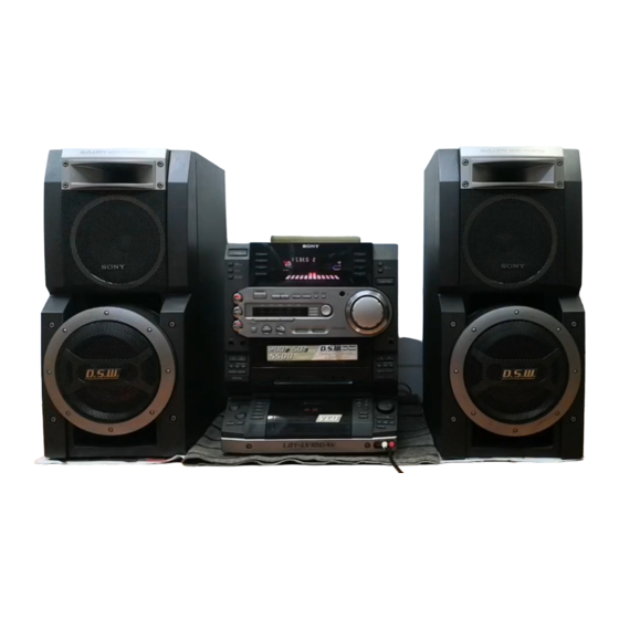
SERVICE MANUAL
• HCD-LV100AV is the Amplifier, CD player,
Tape Deck and Tuner section in LBT-LV100AV.
Manufactured under license from Dolby
Laboratories Licensing Corporation.
"DOLBY" and the double-D symbol ; are
trademarks of Dolby Laboratories Licensing
Corporation.
Amplifier section
Front Speaker:
The following measured at AC 120/220/240 V,
50Hz
DIN power output (Rated)
150 + 150 watts
(6 ohms at 1 kHz, DIN)
Continuous RMS power output (Reference)
200 + 200 watts
(6 ohms at 1 kHz, 10%
THD)
Center Speaker:
DIN power output (Rated)
35 watts
(8 ohms at 1 kHz, DIN)
Continuous RMS power output (Reference)
50 watts
(8 ohms at 1 kHz, 10%
THD)
Rear Speaker:
DIN power output (Rated)
35 + 35 watts
(8 ohms at 1 kHz, DIN)
Continuous RMS power output (Reference)
50 + 50 watts
(8 ohms at 1 kHz, 10%
THD)
HCD-LV100AV
CD
Section
Tape deck
Section
SPECIFICATIONS
Inputs
PHONO IN (phono jacks):sensitivity 3 mV,
impedance 47 kilohms
MIC 1/2 (phone jack):
sensitivity 1 mV,
impedance 10 kilohms
VIDEO1 IN (phono jacks): sensitivity 250 mV,
impedance 47 kilohms
VIDEO2 IN (phono jacks): sensitivity 250 mV,
impedance 47 kilohms
MD IN (phono jacks):
sensitivity 450 mV,
impedance 47 kilohms
DVD INPUT
FRONT, REAR, CENTER, WOOFER (phono jacks):
sensitivity 450 mV,
impedance 47 kilohms
Outputs
PHONES (stereo phone jack):
accepts headphones of 8
ohms or more
VIDEO OUT (phono jack):
voltage 250 mV,
impedance 1 kilohm
MD OUT (phono jacks):
voltage 250 mV,
impedance 1 kilohm
WOOFER OUT (phono jack):
voltage 1 V, impedance
1 kilohm
FRONT SPEAKER:
accepts impedance of 6 to
16 ohms
CENTER SPEAKER:
accepts impedance of 8 to
16 ohms
REAR SPEAKER:
accepts impedance of 8 to
16 ohms
COMPACT Hi-Fi STEREO SYSTEM
Model Name Using Similar Mechanism
CD Mechanism Type
Base Unit Name
Optical Pick-up Name
Model Name Using Similar Mechanism
Tape Transport Mechanism Type
Video section
Inputs
VIDEO1 IN (phono jacks): 1 V p-p, 75 ohms
VIDEO2 IN (phono jacks): 1 V p-p, 75 ohms
Outputs
VIDEO OUT (phono jack):1 V p-p, 75 ohms
S-VIDEO OUT (4-pin/mini-DIN jack):
VIDEO CD/CD player section
System
Laser
Laser output
Wavelength
Frequency response
Signal-to-noise ratio
Dynamic range
Video color system format
E Model
HCD-VR90AV
CDM37L-5BD34L
BU-5BD34L
KSS-213D/Q-NP
NEW
TCM-230PWR12
Y: 1V p-p, unbalanced,
Sync negative,
C: 0.286 V p-p,
load impedance 75 ohms
Compact disc and digital
audio system
Semiconductor laser
( = 780 nm)
Emission
duration: continuous
Max. 44.6 W*
* This output is the value
measured at a distance of
200 mm from the
objective lens surface on
the Optical Pick-up Block
with 7 mm aperture.
780 – 790 nm
2 Hz – 20 kHz (±0.5 dB)
More than 90 dB
More than 90 dB
NTSC, PAL
— Continued on next page —
Advertisement
Table of Contents

Related Manuals for Sony HCD-LV100AV


Summary of Contents for Sony HCD-LV100AV
- Page 1 HCD-LV100AV SERVICE MANUAL E Model • HCD-LV100AV is the Amplifier, CD player, Tape Deck and Tuner section in LBT-LV100AV. Manufactured under license from Dolby Model Name Using Similar Mechanism HCD-VR90AV Laboratories Licensing Corporation. CD Mechanism Type CDM37L-5BD34L “DOLBY” and the double-D symbol ; are...
- Page 2 COMPONENTS IDENTIFIED BY MARK 0 OR DOTTED LINE WITH MARK 0 ON THE SCHEMATIC DIAGRAMS AND IN THE PARTS LIST ARE CRITICAL TO SAFE OPERATION. REPLACE THESE COMPONENTS WITH SONY PARTS WHOSE PART NUMBERS APPEAR AS SHOWN IN THIS MANUAL OR IN SUPPLEMENTS PUBLISHED BY SONY.
-
Page 3: Table Of Contents
TABLE OF CONTENTS 1. GENERAL This appliance is classified as a CLASS 1 LASER product............... 4 The CLASS 1 LASER PRODUCT MARKING is located on the rear exterior. 2. DISASSEMBLY ............. 7 3. SERVICE MODE ............11 4. MECHANICAL ADJUSTMENTS ...... -
Page 4: General
SECTION 1 GENERAL LOCATION OF CONTROLS – Front Panel – 3 4 5 1 ?/1 (POWER) button qg PLAY MODE button 2 DAILY button REPEAT button qh ACTIVE button REC button SLEEP button SELECT button c/CLOCK SET button RETURN button 3 TUNER/BAND button PREV button... - Page 5 – Rear Panel – 1 ANTENNA terminal 2 VOLTAGE SELECTOR 3 SURROUND SPEAKER terminal 4 FRONT SPEAKER terminal 5 NOTE ONLY FOR VCD SYSTEM SELECT switch S VIDEO OUT terminal 6 CD DIGITAL OUT terminal 7 DVD INPUT FRONT jack DVD INPUT REAR jack DVD INPUT WOOFER jack DVD INPUT CENTER jack...
- Page 6 This section is extracted from instruction manual.
-
Page 7: Disassembly
SECTION 2 DISASSEMBLY Note: Follow the disassembly procedure in the numerical order given. 3-1. UPPER CASE 5 Four screws 6 Upper case (BVTT 3 × 6) (Remove in the direction of the arrows) 4 Screws (BVTP3 × 8) 1 Three screws (CASE3 TP2) 3 Two screws (BVTP3 ×... - Page 8 3-3. TAPE MECHANISM DECK (TCM-230PWR12) Two screws (BVTP3 × 8) Two screws (BVTP3 × 8) Tape mechanism deck (TCM-230PWR12) 3-4. MAIN BOARD 1 Wire (flat type) (13 core) (CN441) 5 Eleven screws (BVTP3 × 8) 6 Back panel 7 Connector (CN701) 4 Five screws (BVTP3 ×...
-
Page 9: Video Board (1/2)
3-5. CD MECHANISM DECK (CDM37L-5BD34L) 8 Two screws (BVTP3 × 8) 6 Three screws (BVTP3 × 8) 1 Wire (flat type) 3 Open the cable clamp (13 core) (CN411) 7 Two screws (BVTP3 × 8) 2 Connector (CN412) 4 Connector (CN301) 5 Two screws (BVTP3 ×... - Page 10 3-6. BASE UNIT (BU-5BD34L) 3 Base unit (BU-5BD34L) 2 Boss 1 BU fitting screw 3-7. DISC TABLE Note: When the disc table is installed, adjust the positions of roller cam and mark B as shown in the figure, then set to the groove of disc table.
-
Page 11: Service Mode
SECTION 3 SERVICE MODE MC Cold Reset • The cold reset clears all data including preset data stored in the RAM to initial conditions. Execute this mode when returning the set to the customer. Procedure: Press three buttons c/CLOCK SET , ENTER , and ?/1 simultaneously. 2. - Page 12 AMS Test Mode • This mode is used for checking the AMS operations of the tape deck. 7-819-039-12 Alignment tape, AMS-110A Procedure: Press the ?/1 button to turn the set ON. Set the tape (AMS-110A). Press the three buttons c/CLOCK SET , ENTER , and DISC 3 button simultaneously. “TEST MODE”...
- Page 13 • Display when ended abnormally When the tape deck is abnormal: The state when ended abnormally is displayed. The contents of display are the same as that during aging. When the CD player is abnormal: A message indicating that errors such as “CD MEC ERR” have occurred. Check the error contents in the following error history display mode.
-
Page 14: Video Board (2/2)
[VIDEO CD Color-bars Mode] On this mode, the data of the color-bars signal as a picture signal and the 1 kHz sine wave signal as a sound signal are output by the mechanism controller (IC502) for the video CD signal check. When measurement of the voltage and waveform on the VIDEO board, perform it in this mode. -
Page 15: Mechanical Adjustments
SECTION 4 SECTION 5 MECHANICAL ADJUSTMENTS ELECTRICAL ADJUSTMENTS Precaution DECK SECTION 0 dB=0.775V Clean the following parts with a denatured alcohol-moistened swab: Demagnetize the record/playback head with a head record/playback heads pinch rollers demagnetizer. erase head rubber belts Do not use a magnetized screwdriver for the adjustments. capstan idlers After the adjustments, apply suitable locking compound to the... - Page 16 Tape Speed Adjustment (Deck A) Mode: Playback test tape Note: Set the test mode using the following method and begin tape P-4-A100 speed adjustment. (10kHz, –10dB) oscilloscope In the test mode, the speed will switch to double speed or normal speed each time the HI-SPEED DUB button is pressed. MD OUT Procedure: With the power turned ON, press the c/CLOCK SET button,...
- Page 17 Record Bias Adjustment (Deck B) Record Level Adjustment (Deck B) Procedure: Procedure: INTRODUCTION INTRODUCTION When set to the test mode performed in Tape Speed Adjustment, When set to the test mode performed in Tape Speed Adjustment, when the tape is rewound after recording, the “REC memory mode” when the tape is rewound after recording, the “REC memory mode”...
-
Page 18: Bd Board
CD SECTION E-F Balance (1 Track Jump) Check Note: 1. CD Block is basically designed to operate without adjustment. There- oscilloscope fore, check each item in order given. 2. Use YEDS-18 disc (3-702-101-01) unless otherwise indicated. BD board 3. Use an oscilloscope with more than 10 MΩ impedance. 4. - Page 19 VIDEO SECTION Frequency Adjustment Connection: frequency counter VIDEO board TP508 (27 MHz) – Procedure: 1. Connect the frequency counter to TP508 (27 MHz) on VIDEO board. 2. Turned power switch on. [FUNCTION] 3. Press the button to select the CD. 4.
-
Page 20: Diagrams
SECTION 6 DIAGRAMS NOTE FOR PRINTED WIRING BOARDS AND SCHEMATIC DIAGRAMS 6-1. CIRCUIT BOARDS LOCATION (In addition to this, the necessary note is printed in each block) TRANS board Note on Printed Wiring Board: Note on Schematic Diagram: • X : parts extracted from the component side. •... -
Page 21: Block Diagrams
HCD-LV100AV 6-1. BLOCK DIAGRAMS TUNER/CD/DECK SECION PB EQ DECK-A PB(L) • RCH is omitted RV311 TC REC-L MAIN IC611 LEVEL SECTION • Signal Path (Page 22) HP101 DOLBY : FM HEAD PB EQ TC PB-L MAIN : CD R-CH PB(L) - Page 22 HCD-LV100AV MAIN SECTION R CH J803 HEADPHONS MUTE Q805 M901 FAN DRIVE INPUT SELECT/ Q961,962 GRAPHIC EQ CONT/ ELECTRICAL VOLUME POWER AMP IC101 IC901 TM401 ST-L TUNER INB2 OUT2 SECTION (Page 21) RY401 MUTE RELAY Q113 DRIVE CD-L VIDEO R-CH...
- Page 23 HCD-LV100AV VIDEO CD SECTION XRST SECTION (Page 21) CD DATA/CD BCK/CD LRCK/C2PO Q307 Q308 Q310 IC401 SECTION V L-CH (Page 21) MAIN B.P.F SECTION CD MECHA CONT IC502(2/2) (Page 22) FILTER MUTE Q302 Q454 DEVICE RESET IC401 SHARPNESS Q306 J301...
- Page 24 HCD-LV100AV DISPLAY/POWER SECTION DISPLAY CONTROL IC601 FL601 SPA SIG MAIN BPF0 FLOURESCENT SECTION INDICATOR TUBE SPEANA BPF1 (Page 22) BPF2 IC603 MIC SIG MAIN BPF3 SECTION BPF4 (Page 22) SEG1 ALL BAND SEG23 IC850 ECHO S601-604 GR14 J801 CONT S606-615...
-
Page 25: Schematic Diagram
HCD-LV100AV 6-3. SCHEMATIC DIAGRAM VIDEO Board (1/2) • See page 39 for Waveforms. • See page 59 for IC Pin Function Description. (Page 29) PIN FUNCTION (Page 37) (Page 36) • Voltages and waveforms are dc with respect to ground under no-signal conditions. - Page 26 HCD-LV100AV • See page 39 for Waveforms. • See page 55 for IC Block Diagram. 6-4. SCHEMATIC DIAGRAM VIDEO Board (2/2) • See page 61 for IC Pin Function PIN FUNCTION • Voltages and waveforms are dc with respect to ground under no-signal conditions.
-
Page 27: Printed Wiring Board
HCD-LV100AV 6-5. PRINTED WIRING BOARD VIDEO Board • See page 20 for Circuit Board Location. • Semiconductor Location Ref. No. Location D301 B-5(A) D501 D-2(A) D502 H-1(A) IC101 H-5(A) IC401 B-2(A) IC501 E-3(B) IC502 G-3(B) IC504 G-4(A) C505 D-4(A) IC506... - Page 28 HCD-LV100AV • See page 20 for Circuit Board Location. 6-6. PRINTED WIRING BOARD BD Board VIDEO BOARD (Page 27) • Semiconductor Location Ref. No. Location IC101 E-4(B) IC102 C-5(B) IC103 E-6(B) IC104 F-3(A) Q101 F-6(A)
-
Page 29: Schematic Diagam
HCD-LV100AV 6-7. SCHEMATIC DIAGAM BD Board • See page 39 for Waveforms. • See page 54 for IC Block Diagrams. VIDEO BOARD (Page 25) • Voltages and waveforms are dc with respect to ground under no-signal conditions. no mark: CD STOP... -
Page 30: Printed Wiring Baord
HCD-LV100AV • See page 20 for Circuit Board Location. 6-8. PRINTED WIRING BAORD CD MOTOR Section MAIN BOARD (Page 35) -
Page 31: Cd Motor Section
HCD-LV100AV 6-9. SCHEMATIC DIAGRAM CD MOTOR Section • See page 55 for IC Block Diagrams. TO MAIN BOARD (Page 37) • Voltages and waveforms are dc with respect to ground under no-signal conditions. no mark: CD STOP... -
Page 32: Audio Board
HCD-LV100AV • See page 20 for Circuit Board Location. 6-10. PRINTED WIRING BOARD AUDIO Board • Semiconductor Location Ref. No. Location IC601 IC602 IC611 Q621 Q622 Q623 (21) 1-675-753- MAIN BOARD (Page 35) -
Page 33: Schematic Diagram
HCD-LV100AV 6-11. SCHEMATIC DIAGRAM AUDIO Board • See page 55 for IC Block Diagrams. PB EQ AMP (PLAYBACK) (DECK A) PB LEVEL (L) (DECK A) PB LEVEL (R) (DECK A) PB EQ AMP (DECK B) PB LEVEL (L) (DECK B) A +7.5V... -
Page 34: Leaf Sw Board
HCD-LV100AV • See page 20 for Circuit Board Location. 6-12. PRINTED WIRING BOARD LEAF SW Board (Page 35) 6-13. SCHEMATIC DIAGRAM LEAF SW Board (Page 37) • Voltages and waveforms are dc with respect to ground under no-signal conditions. no mark: TAPE PLAY... -
Page 35: Printed Wiring Board
HCD-LV100AV 6-14. PRINTED WIRING BOARD MAIN Board • See page 20 for Circuit Board Location. • Semiconductor Location Ref. No. Location FRONT INPUT BOARD D191 J703 (Page 46) D192 FRONT REAR J704 D193 CENTER WOOFER WOOFER D194 D201 D333 C776... - Page 36 HCD-LV100AV • See page 54 for IC Block Diagrams. 6-15. SCHEMATIC DIAGRAM MAIN Board (1/3) (Page 25) (Page 47) SURROUNTD AMP BOARD (Page 51) • Voltages and waveforms are dc with respect to ground under no-signal conditions. no mark: TUNER (FM/AM)
-
Page 37: Schematic Diagram
HCD-LV100AV 6-16. SCHEMATIC DIAGRAM MAIN Board (2/3) • See page 56 for IC Pin Function. • See page 39 for Waveforms. (Page 41) 12.1 12.1 PIN FUNCTION 12.3 (Page 25) Q338 DTA114ESA 12.2 12.2 (Page 31) • Voltages and waveforms are dc with respect to ground under no-signal conditions. - Page 38 HCD-LV100AV 6-17. SCHEMATIC DIAGRAM MAIN Board (3/3) (Page 43) 11.4 (Page 49) (Page 49) • Voltages and waveforms are dc with respect to ground under no-signal conditions. no mark: FM...
-
Page 39: Main Board (2/3)
HCD-LV100AV • Waveforms – VIDEO Board – – BD Board – – MAIN Board – IC501 wf (LRCK) IC505 ug (C-OUT) Q308 (Base) IC401 1 IC101 wh (MDP) IC101 yg (LRCK) IC501 q; (XC-IN) 5.2 Vp-p 0.9 Vp-p 2.6 Vp-p 0.5 Vp-p... -
Page 40: Printed Wiring Board
HCD-LV100AV • See page 20 for Circuit Board Location. 6-18. PRINTED WIRING BOARD PANEL FL Board S631 D615 KEY CONTROL S616 R691 (12) TC-B BOARD MAIN BOARD PANEL VR BOARD TC-A BOARD (Page 44) (Page 35) (Page 42) (Page 44) •... -
Page 41: Schematic Diagram
HCD-LV100AV 6-19. SCHEMATIC DIAGRAM PANEL FL Board • See page 39 for Waveform. • See page 55 for IC Block Diagrams. • See page 58 for IC Pin Function. (Page 45) (Page 45) (Page 37) PIN FUNCTION (Page 43) • Voltages and waveforms are dc with respect to ground under no-signal conditions. -
Page 42: Printed Wiring Board
HCD-LV100AV • See page 20 for Circuit Board Location. 6-20. PRINTED WIRING BOARD PANEL VR Board MAIN BOARD (Page 35) D613 D698 D614 D699 S630 S629 5.1CH LOGIC (12) PANEL FL MIC BOARD (Page 46) BOARD (Page 40) • Semiconductor Location Ref. -
Page 43: Schematic Diagram
HCD-LV100AV 6-21. SCHEMATIC DIAGRAM PANEL VR Board • See page 54 for IC Block Diagram. (Page 41) (Page 47) (Page 38) • Voltages and waveforms are dc with respect to ground under no-signal conditions. no mark: FM... -
Page 44: Tc-A/Tc-B/Cd-L/Cd-L2/Cd-R/Cd-R2 Boards
HCD-LV100AV • See page 20 for Circuit Board Location. 6-22. PRINTED WIRING BOARD TC-A/TC-B/CD-L/CD-L2/CD-R/CD-R2 Boards • Semiconductor Location Ref. No. Location D631 D632 PANEL FL D635 BOARD D636 (Page 40) D637 D638 D641 D700 R739 S669 R741 (12) RETURN R738... -
Page 45: Schematic Diagram
HCD-LV100AV 6-23. SCHEMATIC DIAGRAM TC-A/TC-B/CD-L/CD-L2/CD-R/CD-R2 Boards (Page 41) (Page 41) • Voltages and waveforms are dc with respect to ground under no-signal conditions. no mark : FM... -
Page 46: Front Input/Headphone/Mic Boards
HCD-LV100AV • See page 20 for Circuit Board Location. 6-24. PRINTED WIRING BOARD FRONT INPUT/HEADPHONE/MIC Boards C865 R858 C832 C833 R864 R865 R863 C830 R862 C829 IC851 C835 C828 R860 C823 R859 C831 R861 C825 D851 C826 R875 R866 (22) -
Page 47: Schematic Diagram
HCD-LV100AV 6-25. SCHEMATIC DIAGRAM FRONT INPUT/HEADPHONE/MIC Boards • See page 54 for IC Block Diagrams. (Page 36) (Page 43) -7.1 (Page 49) • Voltages and waveforms are dc with respect to ground under no-signal conditions. no mark: FM... -
Page 48: Printed Wiring Board
HCD-LV100AV • See page 20 for Circuit Board Location. 6-26. PRINTED WIRING BOARD PA Board • Semiconductor Location Ref. No. Location D401 D402 D403 D404 C414 D405 C416 C415 C408 D406 R423 D407 C409 D408 D409 D410 D801 D802 C411... -
Page 49: Schematic Diagram
HCD-LV100AV 6-27. SCHEMATIC DIAGRAM PA Board TO SURROUND AMP BOARD (Page 51) (Page 53) (Page 53) (Page 38) (Page 38) (Page 47) The components identified by mark 0 or dotted • Voltages and waveforms are dc with respect to ground line with mark 0 are critical for safety. -
Page 50: Printed Wiring Board
HCD-LV100AV • See page 20 for Circuit Board Location. 7-28. PRINTED WIRING BOARD SURROUND AMP Board • Semiconductor Location Ref. No. Location SURROUND AMP BOARD D101 D151 D191 IC101 Q101 Q103 Q104 Q151 Q181 (22) 1-676-282- MAIN BOARD PA BOARD... -
Page 51: Schematic Diagram
HCD-LV100AV 6-29. SCHEMATIC DIAGRAM SURROUND AMP Board SURROUND AMP BOARD (Page 36) (Page 49) The components identified by mark 0 or dotted • Voltages and waveforms are dc with respect to ground line with mark 0 are critical for safety. -
Page 52: Printed Wiring Board
HCD-LV100AV • See page 20 for Circuit Board Location. 6-30. PRINTED WIRING BOARD TRANS Boards PA BOARD (Page 48) PA BOARD (Page 48) - Page 53 HCD-LV100AV 6-31. SCHEMATIC DIAGRAM TRANS Boards (Page 49) (Page 49) The components identified by mark 0 or dotted line with mark 0 are critical for safety. Replace only with part number specified.
-
Page 54: Ic Block Diagrams
HCD-LV100AV 6-32. IC BLOCK DIAGRAMS – BD Board – – BD Board – IC101 CXD3008Q IC103 CXA2568M-T6 HOLD APC PD AMP 80 79 78 77 76 75 74 73 72 71 70 69 68 67 66 LC/PD APC LD AMP –... - Page 55 – CD MOTOR Board – IC201 TA8409S VREF BLOCK STANDBY BLOCK HEAT CUT OFF BLOCK OUT2 OUT1 VREF – AUDIO Board – IC602 µPC1330HA INVERTER COMPARATER SW R1 SW P1 CONT SW P2 SW R2 – PANEL FL Board – –...
-
Page 56: Ic Pin Function Description
6-33. IC PIN FUNCTION DESCRIPTION • MAIN BOARD IC501 M30622MA-A26FP Pin No. Pin Name Function POWER Power amp ON/OFF signal output POWER Power ON/OFF signal output F-RELAY Front speaker relay control output REAR-RELAY Rear speaker relay control output (Not used) CD-POWER CD power on signal output LINE-MUTE... - Page 57 Pin No. Pin Name Function TUNED Tuned detection for tuner ST-CE Tuner chip enable output ST-DOUT Tuner data output ST-DIN Tuner data input ST-CLK Tuner clock output SENS BD Condition signal input HOLD MODE signal output CD latch signal output XRST CD reset signal output DISC-SENS...
- Page 58 • PANEL FL BOARD IC601 TMP88CC76F-1A25 (FLUORESCENT INDICATOR TUBE DRIVE, LED DRIVE, KET CONTROL) Pin No. Pin Name Function SIRCS Remote commander signal input JOG A Rotary encoder (S702) pulse input LED SCK LED clock signal output LED LATCH LED latch signal output LED DAT LED serial data output LED POWER...
- Page 59 • VIDEO BOARD IC502 M30620MC-A17FP (CD MECHANISM CONTROLLER) Pin No. Pin Name Description SENSE Internal status (SENSE) signal input from the CXD3008Q (IC101) SENSE CLK Sense serial data reading clock signal output to the CXD3008Q (IC101) DSP DATA Serial data output to the CXD3008Q (IC101) DSP LATCH Serial data latch pulse output to the CXD3008Q (IC101) DSP CLK...
- Page 60 Pin No. Pin Name Description 42, 43 Not used (open) SHIMUKE Destination setting terminal “L”: Chinese, “H”: English (fixed at “H” in this set) Vertical synchronized signal input from the MPEG video/audio decoder (IC505) “L” active BUS XWRL Not used (open) LO.BOOST Low boost control signal output terminal Not used (open) AUDIO MUTE...
- Page 61 • VIDEO BOARD IC505 CL680T-D1 (MPEG VIDEO/AUDIO DECODER, VIDEO SIGNAL PROCESSOR) Pin No. Pin Name Description Not used (open) — Ground terminal CD-BCK CD decode bit clock signal (2.8224 MHz) input from the CXD3008Q (IC101) CD-DATA CD decode data input from the CXD3008Q (IC101) CD-LRCK CD decode L/R sampling clock signal (44.1 kHz) input from the CXD3008Q (IC101) CD-C2PO...
- Page 62 Pin No. Pin Name Description RREF Fix the video signal output level control VREF Reference voltage (+1.235V) output terminal AVDD-DAC — Power supply terminal (+3.3V) (for D/A converter) C-OUT Chrominance video signal output terminal AGND-DAC — Ground terminal (for D/A converter) GCK (pin `⁄‚fi...
- Page 63 Pin No. Pin Name Description VDD3 — Power supply terminal (+3.3V) HSEL Command selection signal input from the CD mechanism controller (IC502) CDG-SDATA Not used (fixed at “L”) CDG-VFSY Not used (fixed at “L”) CDG-S0S1 Not used (fixed at “L”) 125 to 128 Not used (open)
-
Page 64: Exploded Views
SECTION 7 EXPLODED VIEWS NOTE: • -XX, -X mean standardized parts, so they may • Hardware (# mark) list and accessories and The components identified by mark 0 or have some differences from the original one. packing materials are given in the last of this dotted line with mark 0 are critical for safety. - Page 65 7-2. FRONT PANEL SECTION-1 TCM-230PWR12 supplied supplied supplied with S701 CD-L2 board CD-R2 board Ref. No. Part No. Description Remarks Ref. No. Part No. Description Remarks 4-226-062-21 PLATE, ORNAMENTAL 4-224-104-21 DAMPER 4-951-620-01 SCREW (2.6X8), +BVTP 4-225-503-01 KNOB(CD) 1-676-276-11 FRONT INPUT BOARD 4-225-517-01 HOLDER (CASE) X-4952-504-1 LID(TC) ASSY 4-225-522-01 SPRING (DECK-A)
- Page 66 7-3. FRONT PANEL SECTION-2 not supplied supplied with J801, J802 supplied supplied with J803 supplied supplied Ref. No. Part No. Description Remarks Ref. No. Part No. Description Remarks X-4952-448-1 PANEL ASSY, FRONT 4-226-882-01 LEVER (EJECT-C) 4-948-236-21 CUSHION (107) 4-226-881-01 LEVER (EJECT-B) 4-225-501-01 KNOB (VOL) 4-226-880-01 LEVER (EJECT-A) 4-226-888-01 LEVER (EJECT-B)
- Page 67 7-4. CHASSIS SECTION supplied supplied T951 supplied supplied supplied CDM37M-5BD32L supplied supplied 162 161 Ref. No. Part No. Description Remarks Ref. No. Part No. Description Remarks 1-676-267-11 TRANS BOARD A-4428-146-A MAIN BOARD, COMPLETE * 152 4-988-533-01 HOLDER, PWB X-4941-228-1 FOOT (F22125H-M) 3-703-244-00 BUSHING (FBS001), CORD A-4724-882-A VIDEO BOARD, COMPLETE A-4428-938-A PA BOARD, COMPLETE...
- Page 68 7-5. TAPE MECHANISM DECK SECTION-1 (TCM-230PWR12) HP101 HRPE101 Ref. No. Part No. Description Remarks Ref. No. Part No. Description Remarks 3-376-464-11 SCREW(+PTT 2.6X6),GROUND POINT 3-017-366-01 BASE (PINCH LEVER REV) 3-911-116-42 RIVET, PUSH 3-016-567-02 SPRING (CASSETTE), LEAF 3-016-574-01 SPRING (HEAD), TENSION 1-675-753-21 AUDIO BOARD X-3374-156-4 PINCH LEVER (REV) ASSY HP101...
- Page 69 7-6. TAPE MECHANISM DECK SECTION-2 (TCM-230PWR12) Ref. No. Part No. Description Remarks Ref. No. Part No. Description Remarks X-4952-881-1 CHASSIS ASSY, MAIN A-2007-852-A LEAF SW BOARD, COMPLETE 3-041-946-01 BELT (CAPSTAN B) 4-228-450-01 SPRING (REVERSE SLIDER),TORSION 4-227-239-01 BELT (CAPSTAN C) 3-019-208-01 WASHER, STOPPER 3-016-568-01 BRACKET (MOTOR) 3-027-453-01 SPRING (GROUND), TENSION X-3378-247-1 FLYWHEEL (A-FWD) ASSY...
- Page 70 7-7. CD MECHANISM DECK SECTION (CDM37L-5BD34L) supplied M201 supplied Ref. No. Part No. Description Remarks Ref. No. Part No. Description Remarks 4-987-976-01 SCREW, STEP * 514 A-4673-765-A CD MOTOR BOARD, COMPLETE 4-944-490-01 BELT (TIMING) 4-978-426-01 INDICATOR (NO.) A-4660-978-A GEAR (PULLEY) ASSY * 516 1-659-059-13 LED BOARD 4-978-421-01 GEAR (MID)
- Page 71 7-8. BASE UNIT SECTION (BU-5BD34L) M101 M102 Ref. No. Part No. Description Remarks Ref. No. Part No. Description Remarks 0 601 8-820-020-02 OPTICAL PICK-UP BLOCK KSS-213D/Q-NP A-4724-653-A BD BOARD, COMPLETE 1-769-069-11 WIRE (FLAT TYPE) (16 CORE) 4-951-620-01 SCREW (2.6X8), +BVTP 4-917-567-21 GEAR (M) 3-713-786-51 SCREW +P 2X3 4-951-940-01 INSULATOR (BU)
-
Page 72: Electrical Parts List
SECTION 8 AUDIO ELECTRICAL PARTS LIST NOTE: • Due to standardization, replacements in the • CAPACITORS: • SEMICONDUCTORS parts list may be different from the parts uF: µF In each case, u: µ, for example: specified in the diagrams or the components •... - Page 73 AUDIO Ref. No. Part No. Description Remarks Ref. No. Part No. Description Remarks < VARIABLE RESISTOR > < IC > RV301 1-238-598-11 RES, ADJ, CARBON 2.2K IC101 8-752-397-42 IC CXD3008Q RV311 1-238-598-11 RES, ADJ, CARBON 2.2K IC102 8-759-549-28 IC BA5974FP-E2 RV341 1-241-768-11 RES, ADJ, CARBON 220K IC103...
- Page 74 CD MOTOR CD-L (CD-L2) CD-R (CD-R2) Ref. No. Part No. Description Remarks Ref. No. Part No. Description Remarks R175 1-216-025-91 RES-CHIP 1/10W R734 1-249-429-11 CARBON 1/4W R203 1-216-025-91 RES-CHIP 1/10W R735 1-249-431-11 CARBON 1/4W R204 1-216-025-91 RES-CHIP 1/10W R736 1-249-434-11 CARBON 1/4W R205 1-216-025-91 RES-CHIP...
- Page 75 CD-R (CD-R2) FRONT INPUT HEADPHONE LEAF SW Ref. No. Part No. Description Remarks Ref. No. Part No. Description Remarks S681 1-762-875-21 SWITCH, KEYBOARD (PLAY MODE) < DIODE > S682 1-762-875-21 SWITCH, KEYBOARD (REPEAT) S701 1-473-393-11 ENCODER, ROTARY (AMS) D1001 8-719-991-33 DIODE 1SS133T-77 D1002 8-719-991-33 DIODE 1SS133T-77 **************************************************************...
- Page 76 MAIN Ref. No. Part No. Description Remarks Ref. No. Part No. Description Remarks A-4428-146-A MAIN BOARD, COMPLETE C212 1-126-959-11 ELECT 0.47uF 20.00% 50V C213 1-136-165-00 MYLAR 0.1uF 5.00% 50V ********************* C214 1-163-038-91 CERAMIC CHIP 0.1uF 4-875-327-31 HEATSINK C215 1-163-038-91 CERAMIC CHIP 0.1uF 7-685-646-79 SCREW+BVTP TYPE2 N-S...
- Page 77 MAIN Ref. No. Part No. Description Remarks Ref. No. Part No. Description Remarks C305 1-126-964-11 ELECT 10uF 20.00% 50V C655 1-130-479-00 MYLAR 0.0047uF 5% C306 1-126-960-11 ELECT 20.00% 50V C656 1-130-473-00 MYLAR 0.0015uF 5% C307 1-126-959-11 ELECT 0.47uF 20.00% 50V C657 1-136-159-00 MYLAR 0.033uF...
- Page 78 MAIN Ref. No. Part No. Description Remarks Ref. No. Part No. Description Remarks C953 1-126-964-11 ELECT 10uF 20.00% 50V < IC > C954 1-126-964-11 ELECT 10uF 20.00% 50V C955 1-126-924-11 ELECT 330uF 20.00% 10V IC101 8-759-571-54 IC M62493FP C961 1-163-038-91 CERAMIC CHIP 0.1uF IC181 8-759-009-06 IC MC14052BFEL...
- Page 79 8-729-029-86 TRANSISTOR DTC124ESA-TP R213 1-216-097-91 RES-CHIP 100K 1/10W Q914 8-729-029-86 TRANSISTOR DTC124ESA-TP R214 1-216-097-91 RES-CHIP 100K 1/10W Q921 8-729-018-59 TRANSISTOR 2SB1375(LB-SONY) R271 1-216-057-00 METAL CHIP 2.2K 1/10W Q931 8-729-040-20 TRANSISTOR RT1P137L-TP R272 1-216-097-91 RES-CHIP 100K 1/10W Q932 8-729-029-86 TRANSISTOR DTC124ESA-TP...
- Page 80 MAIN Ref. No. Part No. Description Remarks Ref. No. Part No. Description Remarks R322 1-216-071-00 METAL CHIP 8.2K 1/10W R541 1-216-073-00 METAL CHIP 1/10W R332 1-216-045-00 METAL CHIP 1/10W R542 1-216-025-91 RES-CHIP 1/10W R333 1-216-057-00 METAL CHIP 2.2K 1/10W R543 1-216-025-91 RES-CHIP 1/10W R334...
- Page 81 MAIN Ref. No. Part No. Description Remarks Ref. No. Part No. Description Remarks R652 1-216-049-91 RES-CHIP 1/10W R962 1-216-079-00 METAL CHIP 1/10W R653 1-216-089-91 RES-CHIP 1/10W R963 1-216-057-00 METAL CHIP 2.2K 1/10W R654 1-216-049-91 RES-CHIP 1/10W R655 1-216-115-00 METAL CHIP 560K 1/10W <...
- Page 82 Ref. No. Part No. Description Remarks Ref. No. Part No. Description Remarks < IC > C809 1-130-777-00 MYLAR 0.1uF 10.00% 100V C810 1-128-562-11 ELECT 47uF 20.00% 100V IC850 8-759-634-50 IC M5218AL C811 1-130-493-00 MYLAR 0.068uF IC851 8-759-450-96 IC M65850P C812 1-130-493-00 MYLAR 0.068uF C813...
- Page 83 Ref. No. Part No. Description Remarks Ref. No. Part No. Description Remarks D831 8-719-510-68 DIODE D5SBA204101 R419 1-249-389-11 CARBON 1/4W F D833 8-719-200-82 DIODE 11ES2-NTA1B R420 1-249-389-11 CARBON 1/4W F D834 8-719-200-82 DIODE 11ES2-NTA1B R421 1-249-389-11 CARBON 1/4W F D835 8-719-200-82 DIODE 11ES2-NTA1B R422 1-260-076-11 CARBON...
- Page 84 PANEL FL Ref. No. Part No. Description Remarks Ref. No. Part No. Description Remarks R836 1-249-417-11 CARBON 1/4W F C624 1-104-664-11 ELECT 47uF 20.00% 16V R837 1-249-435-11 CARBON 1/4W C625 1-126-963-11 ELECT 4.7uF 20.00% 50V R838 1-249-435-11 CARBON 1/4W C626 1-126-964-11 ELECT 10uF 20.00% 50V...
- Page 85 PANEL FL PANEL VR Ref. No. Part No. Description Remarks Ref. No. Part No. Description Remarks Q607 8-729-029-23 TRANSISTOR DTA114TSA-TP R667 1-249-441-11 CARBON 100K 1/4W Q608 8-729-047-58 TRANSISTOR DTC114TLTL2 R680 1-249-411-11 CARBON 1/4W Q609 8-729-047-58 TRANSISTOR DTC114TLTL2 R681 1-249-440-11 CARBON 1/4W Q610 8-729-047-58 TRANSISTOR...
- Page 86 PANEL VR TRANS Ref. No. Part No. Description Remarks Ref. No. Part No. Description Remarks D614 8-719-057-97 DIODE SEL5923A-TP15 (DVD 5.1CH) R776 1-247-843-11 CARBON 3.3K 1/4W D616 8-719-058-04 DIODE SEL5223S-TP15 (ENTER) R777 1-249-407-11 CARBON 1/4W F D618 8-719-058-04 DIODE SEL5223S-TP15 (EFFECT) R778 1-249-407-11 CARBON 1/4W F...
- Page 87 TRANS SURROUND AMP Ref. No. Part No. Description Remarks Ref. No. Part No. Description Remarks < CONNECTOR > < CONNECTOR > CN905 1-564-321-00 PIN, CONNECTOR 2P CN101 1-691-772-11 PLUG (MICRO CONNECTOR) 10P * CN951 1-564-214-11 PIN, CONNECTOR (B3PS-VH) 3P * CN952 1-564-526-11 PLUG, CONNECTOR 11P <...
- Page 88 SURROUND AMP TABLE SENSOR TC-A TC-B VIDEO Ref. No. Part No. Description Remarks Ref. No. Part No. Description Remarks R189 1-260-076-11 CARBON 1/2W R716 1-249-417-11 CARBON 1/4W F R190 1-249-437-11 CARBON 1/4W R717 1-249-418-11 CARBON 1.2K 1/4W F R191 1-249-417-11 CARBON 1/4W F R718 1-249-420-11 CARBON...
- Page 89 VIDEO Ref. No. Part No. Description Remarks Ref. No. Part No. Description Remarks C505 1-126-206-11 ELECT CHIP 100uF 6.3V <IC > C506 1-165-319-11 CERAMIC CHIP 0.1uF C507 1-126-206-11 ELECT CHIP 100uF 6.3V IC101 8-759-701-40 IC NJM2100M(TE2) C509 1-163-275-11 CERAMIC CHIP 0.001uF 5.00% 50V IC401...
- Page 90 VIDEO Ref. No. Part No. Description Remarks Ref. No. Part No. Description Remarks < RESISTOR > R464 1-216-025-91 RES-CHIP 1/10W R501 1-216-025-91 RES-CHIP 1/10W R101 1-216-073-00 METAL CHIP 1/10W R502 1-216-025-91 RES-CHIP 1/10W R102 1-208-441-61 RES-CHIP 1.5K 1/10W R503 1-216-025-91 RES-CHIP 1/10W R103 1-208-441-61 RES-CHIP...
- Page 91 VIDEO Ref. No. Part No. Description Remarks Ref. No. Part No. Description Remarks R577 1-216-081-00 METAL CHIP 1/10W 0 156 1-569-008-21 ADAPTOR, CONVERSION 2P R578 1-216-081-00 METAL CHIP 1/10W 0 157 1-777-071-51 CORD, POWER R579 1-216-073-00 METAL CHIP 1/10W 1-790-660-11 WIRE (FLAT TYPE) (23 CORE) R580 1-216-073-00 METAL CHIP 1/10W...
- Page 92 HCD-LV100AV Sony Corporation 9-929-233-11 2000D1623-1D Home Audio Division Company Printed in Japan © 2000.4 Published by Quality Assurance Dept.