Table of Contents
Advertisement
Quick Links
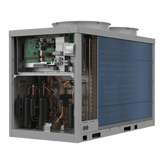
CS 3000 AWP
de
Luft-Wasser-Wärmepumpe
en
Air to Water Heat Pump
es
Bomba de calor aire - agua
fr
Pompe à chaleur air-eau
it
Pompa di calore aria - acqua
pl
Pompa ciepła powietrze-woda
pt
Bomba de calor ar-água
Installations- und Bedienungsanleitung . . . . . . . . . . . . . . . . . . . . . . . . . . . . . . . . . . . . . 2
Installation and operating instructions . . . . . . . . . . . . . . . . . . . . . . . . . . . . . . . . . . . . . 43
Instrucciones de montaje y uso . . . . . . . . . . . . . . . . . . . . . . . . . . . . . . . . . . . . . . . . . . . 83
Notice d'installation et d'utilisation . . . . . . . . . . . . . . . . . . . . . . . . . . . . . . . . . . . . . . . 123
Installazione e istruzioni per l'uso . . . . . . . . . . . . . . . . . . . . . . . . . . . . . . . . . . . . . . . . 164
Instrukcja montażu/obsługi . . . . . . . . . . . . . . . . . . . . . . . . . . . . . . . . . . . . . . . . . . . . . 205
Manuais de instalação/utilização . . . . . . . . . . . . . . . . . . . . . . . . . . . . . . . . . . . . . . . . . 246
Advertisement
Table of Contents

Related Manuals for Bosch CS 3000 AWP


Summary of Contents for Bosch CS 3000 AWP
- Page 1 CS 3000 AWP Luft-Wasser-Wärmepumpe Installations- und Bedienungsanleitung ........2 Air to Water Heat Pump Installation and operating instructions .
-
Page 2: Table Of Contents
Table of contents Table of contents 15 Modbus ..........72 15.1 Overview of service functions . -
Page 3: Explanation Of Symbols And Safety Instructions
Explanation of symbols and safety instructions Explanation of symbols and safety instructions Explanation of symbols Warnings In warnings, signal words at the beginning of a warning are used to indicate the type and seriousness of the ensuing risk if measures for minimizing danger are not taken. -
Page 4: Information On Refrigerant Gas
Product Information • type of refrigerant Product Information • refrigerant charge • manufacturer logo and address Declaration of Conformity The type plate must never be removed. The unit contains fluorinated The design and operating characteristics of this product comply with the greenhouse gases. -
Page 5: Scope Of Delivery
Pre-installation Scope of delivery • Maximum ambient temperature: +48ºC (possible safety valve opening); • Maximum relative humidity: 95% (possible damages to electrical components). Any disputes must be made within 8 days from the date of the delivery. Complaints after this period are invalid. Removal of packaging When removing the packaging, be careful not to damage the unit. -
Page 6: Installation Location
Installation location Handling • Install the unit raised from the ground; ▶ Check if all the handling equipment complies with local safety • Bearing point aligned and levelled; regulations (cran, forklifts, ropes, hooks, etc.); • Discharged condensation water must not cause harm/danger to ▶... -
Page 7: Accessories
Water systems and pipework Accessories V [m ] Installation of the anti-vibration coupling 2,60 Place the anti-vibration coupling between the unit and the base. 2,40 2,20 Use the holes on the unit frame (15 mm diameter). 2,00 1,80 1,60 1,40 If the anti-seismic spring couplings are installed, the total height of the 1,20 unit increases. -
Page 8: Dirt Trap
Water systems and pipework An option to remove pollutants is to install a filter. Be aware that most of the glycol types are corrosive under 20%. Mix the water glycol mix proper before filling it in the system, otherwise the unit can be damaged. -
Page 9: Hydraulic Schemes
Water systems and pipework Victaulic connections ▶ Remove the supplied connection union by acting on the connection joint; ▶ Weld the union to the installation pipe; ▶ Perform the connection between the installation pipe and the evaporator, using the joint. Do not weld the system pipe with the victaulic connection joint. -
Page 10: Electrical Connections
Fig. (Graphic 384, APC board XT1 power connection terminal and the type of signal. XT2 low voltage terminal for CS 3000 AWP - AWP31, AWP36, AWP41, Lay the cables far from power cables or cables having a different tension AWP53 and AWP59) and that are able to emit electromagnetic disturbances. - Page 11 (APR board for CS 3000 AWPCS 3000 AWP - AWP16AWP59) Fig. ( Graphic 386, Overview placement APC-, APR board XT1 and XT2 terminal for CS 3000 AWP AWP16 - AWP24) • SA4 - Remote ON/OFF selector • SA5 - Remote “heating/cooling” selector Fig.
-
Page 12: Advanced Remote Control Board
Electrical connections a 10m long cable. Connect it to the free connector labelled “T5” in the electrical panel. – Contact on XT2-board: 3-4. • Keypad remote connections – The keypad is wired on the unit. It can be disassembled and 12/04/2019 10:35A installed remotely. -
Page 13: Domestic Hot Water
Start-up 1. Disconnect the probe Taf1 supplied and connected as standard on ON/OFF the unit (main board-CN69). 2. Connect the probe Taf1 supplied as spare part with the 10mt cable (main board-CN69). D-S-P 3. After connecting the cable put the probe on the domestic hot water SILENT line. -
Page 14: Refrigerant Circuit
Start-up Preliminary checks YES NO Unit power supply OFF Scheduling customisation Complete and available unit documentation YES NO Table 54 Safe access Suitable frame to withstand unit weight + people Refrigerant circuit weight ▶ Visually inspect the refrigerant circuit: the presence of oil stains can Functional clearances be a symptom of leakage (caused e.g. -
Page 15: Remote Controls
Control unit Voltage Control unit ▶ Check that the air and water temperatures are within in the operating limits. HMI overview ▶ Start-up the unit. Keys of the HMI While the unit is operative, i.e. in stable conditions nearing operating ones, check: •... -
Page 16: Menu Structure
Control unit Menu structure MENU • Mode • User menu • Project menu • Service menu MODE • Heat • Cool • DHW USER MENU • Query • Timer • General setting • Double setting • Snow-blowing switch • Silent switch •... -
Page 17: Menu Settings
Control unit DHW SWITCH • Select address • Hot water switch • Hot water priority • Yes/No SERVICE MENU (reserved for service centres) • State query • Clear history errors • Setting address • Heat control • Temperature compensation • Pump control •... - Page 18 Control unit Domestic hot water User Menu query The ACS, if present and enabled, must be activated. • Press MENU – Press to select MODE – Press OK – Press to select the DHW mode – Press ON/OFF – Press OK to confirm Fig.
- Page 19 Control unit Fig. 88 Fig. 85 TIMER menu - WEEKLY TIMER TIMER menu - DAILY TIMER • The weekly timing and the weekly timing switch can be selected by • Press to select timer 1 or timer 2 , and Monday to Sunday can be selected by •...
- Page 20 Control unit Fig. 90 Fig. 93 USER menu - SNOW-BLOWING switch • If enabled, the function activates the fans in order to avoid the accumulation of snow • The fans start for 2 minutes every 30 minutes. With T air < 3ºC and unit stopped •...
-
Page 21: Troubleshooting
Troubleshooting Standby: unit address (88 to the left) + online number (88 to the right) On: frequency defrosting: dFdF 23.xx Compressor current B 24.xx 25.xx Electronic expansion valve opening A (actual valve/20) 26.xx Electronic expansion valve opening B (actual valve/20) 27.xx Electronic expansion valve opening C (actual valve/4) 28.xx... - Page 22 Troubleshooting • Condenser high temperature; Error code Description • High temperature difference between the input and output water; IPM module error, circuit B • Antifreeze protection; Fan B module • Drain temperature sensor malfunction; EEPROM error - inverter B module •...
-
Page 23: Gas Safety Warnings (R32)
Gas safety warnings (R32) Table 58 • If an indirect refrigerant circuit is used, the secondary circuits must be checked to verify the presence of refrigerants; the marking on the equipment remains visible and readable; Gas safety warnings (R32) • Make sure markings and symbols are always readable; pipes or components must be installed in a position that makes improbable Area checks their exposure to substances that may corrode the components... - Page 24 Gas safety warnings (R32) keep into consideration the effects of tine or the continuous vibration • Before loading the system with refrigerant, check that the cooling caused e.g. by compressors or fans. system is earthed; • Label the system when fully charged (unless already labelled); Detection of flammable refrigerants •...
-
Page 25: Maintenance
Maintenance • Recovery equipment must be perfectly functioning with the General respective instruction booklets at hand and they must be suitable to Maintenance must be performed by authorized centres or by qualified recover flammable refrigerants. A series of perfectly functioning personnel. - Page 26 Maintenance Standby mode If foreseen a long period of inactivity; turn off the power, in order to prevent the risk of freezing (use glycol or empty the system). Also disconnect the voltage to avoid electric risks or damages following lightning. With lower temperatures keep heaters turned on in the electrical panel (option).
-
Page 27: Circulation Pumps
Decommissioning On the schedule keep track of: Decommissioning • The date; • The intervention description; Disconnection • The carried out measures. 11.2 Circulation pumps Before performing any operation, read the Maintenance chapter. Please check: • If there is no leaks; Avoid leak or spills into the environment. -
Page 28: Warnings
Warnings Easy access to the unit by children, unauthorised persons or animals Warnings may be the source of accidents, some serious. Install the unit in areas which are only accessible to authorised person 13.1 Residual risks and/or provide protection against intrusion into the danger zone. In this section the most common risk situations are indicated as these Electric parts cannot be controlled by the manufacturer and could be a source of... -
Page 29: Modular Configuration Units
Modular configuration units Modular configuration units This feature allows up to 16 units to be connected. The system is completely controlled by the Master unit. Each connected Adr.2 Adr.1 Adr.0 module is identified by an address, from 0 to 15: the Master unit is identified as 0. -
Page 30: Single/ Multiple Pump System
Modular configuration units 14.1 Single/ multiple pump system If some of the slave units do not have the DHW option: Set up the DIP S12-2 according to the system type. • Configure a unit without a DHW option as the master •... -
Page 31: Modbus
Modbus The address of the unit is shown on display “DSP1” on the main keypad. • The control activates 50% of the resources in sequence based on the set address; Addressing controls • After a time interval (default: 240 seconds); A maximum of 16 controls can be addressed, with address from 0 to 15;... -
Page 32: Module Configuration
Modbus Enabling Address Function Description Press Menu + for 3 seconds Point 1 Temperature 25 °C ~30 °C compensation in cooling Service Menu > Setting Address >Modbus enable > YES Point 2 Temperature 35 °C ~40 °C Reading register, writing a single register, multiple register writing. compensation in cooling Temperature... - Page 33 Modbus Code Function Description Code Function Description 256 +(Address) 0 = Off 286 +(Address) Pump control type 1 = multiple pumps *100 *100 1 = On 0 = single pump 257 +(Address) 0 = Off 287 +(Address) Unit type *100 *100 1 = ON 289 +(Address)
-
Page 34: Technical Specifications And Reports
Technical specifications and reports Faults and errors In the BMS reading register 272, 273 displays one of the following errors codes in decimal format, only considering the BYTE LOW. Only consider the last two alphanumeric digits of the code. Faults code Fault number (dec) Fault code Fault number (dec) -
Page 35: Construction
Technical specifications and reports SIZE Heating capacity (EN 24,3 27,1 31,4 48,6 54,0 62,0 73,4 84,0 14511:2018) COP (EN 14511:2018) 2 3,30 3,27 3,20 3,32 3,26 3,10 3,19 3,19 Cooling Cooling capacity (EN 22,3 25,8 29,0 42,0 48,0 55,0 68,9 79,8 14511:2018) EER (EN 14511:2018) -
Page 36: Sound Levels
Technical specifications and reports SIZE AWP16 AWP19 AWP24 AWP31 AWP36 AWP41 AWP53 AWP59 Installed unit power Heating system Connection type Victaulic 1” Victaulic 1” Victaulic 1” Victaulic 2” Victaulic 2” Victaulic 2” Victaulic 2” Victaulic 2” Maximum water side pressure Minimum system volume for defrost Minimum circuit water... - Page 37 Technical specifications and reports Super Silent Mode SIZE AWP16 AWP19 AWP24 AWP31 AWP36 AWP41 AWP53 AWP59 Sound pressure level dB(A) 53.4 58.9 58.9 54.4 54.4 58.1 57.5 60.3 Sound power level dB(A) Table 71 Sound levels refer to units with maximum test conditions. For maximum capacity supplied in silent mode, a correction factor of 0,83 shall be used.
-
Page 38: Dimensional Drawings
Technical specifications and reports 16.4 Dimensional drawings AWP16, AWP19, AWP24 10 4 1005 1861 1920 0010045735-003 Compressor enclosure Electrical panel Power input Inlet water connection 1” 1/2 victaulic Outlet water connection 1” 1/2 victaulic Functional spaces Electrical fan Unit fixing holes External exchanger [10] DHW inlet (optional) 1 1/2”... - Page 39 Technical specifications and reports AWP31, AWP36, AWP41 2274 1060 2204 0010045736-003 Compressor enclosure Electrical panel Power input Inlet water connection 2” victaulic Outlet water connection 2” victaulic Inlet water connection 2” victaulic Outlet water connection 2” victaulic Electric fan External exchanger [10] Unit fixing holes [11] Functional spaces SIZE...
- Page 40 Technical specifications and reports AWP53, AWP59 1100 3300 2715 3221 1029 0010045737-003 Compressor enclosure Electrical panel Power input Inlet water connection 2” victaulic Outlet water connection 2” victaulic Inlet DHW connection 2” victaulic Outlet DHW connection 2” victaulic Electric fan External exchanger [10] Unit fixing holes [11] Functional spaces...
-
Page 41: Environmental Protection And Disposal
Data Protection Officer, Information Security and Privacy (C/ISP), of with other waste, and instead must be taken to the waste Robert Bosch GmbH, Postfach 30 02 20, 70442 Stuttgart, GERMANY. collection points for treatment, collection, recycling and You have the right to object, on grounds relating to your particular disposal. - Page 42 Aviso de Proteção de Dados 0010044571-001 0010044572-001 CS3000 AWP – 6721852570 (2023/04)
- Page 43 Aviso de Proteção de Dados 17 B 0010044569-001 0010044570-001 CS3000 AWP – 6721852570 (2023/04)
- Page 44 Aviso de Proteção de Dados L1L2 L3 N ALARM CN24 CN85 CN26 CN33 CN27 CN25 L1/L2/L3 VACSX VACS AMOD VACS 220-240V~ CUSTOMER 466_12 466_10 170_31 466_10 13.2 13.2 13.2 13.2 Max current (RMS): 5A 13.2 0010050133-001 L1L2 L3 N ALARM CN24 CN85 CN26...
- Page 45 Aviso de Proteção de Dados CUSTOMER 13.2 CN14 CN15 CN13 CN12 CN22 CN21 HEAT-SET HEAT-SET D-S-P SILENT 4...20mA POWER 12VAC/DC 0-10V 0-10V MIDEA HMI 4...20mA 0...5V S2-ON CN23 CN26 CN20 S7-ON S1-ON MODBUS MODBUS E_GasBoiler REMAU 835_12 13.2 0010050134-001 0010050145-001 CS3000 AWP –...
- Page 46 Aviso de Proteção de Dados 0010050146-001 CS3000 AWP – 6721852570 (2023/04)
- Page 50 Bosch Thermotechnik GmbH Junkersstrasse 20-24 73249 Wernau, Germany www.bosch-thermotechnology.com...