Table of Contents
Advertisement
Quick Links
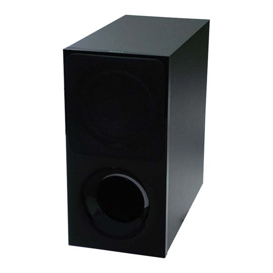
SA-WX9000F/WXF9000
SERVICE MANUAL
Ver. 1.0 2018.01
• SA-WX9000F is the active subwoofer in HT-X9000F.
• SA-WXF9000 is the active subwoofer in HT-XF9000.
• All of the units included in the HT-X9000F (SA-X9000F/SA-
WX9000F/Remote control) or HT-XF9000 (SA-XF9000/
SA-WXF9000/Remote control) are required to confi rm-
ing operation of SA-WX9000F/WXF9000. Check in ad-
vance that you have all of the units.
• For the TEST MODE for this unit, refer to the service manual of HT-X9000F/XF9000.
SPECIFICATIONS
POWER OUTPUT (reference)
100 W (at 4 ohms, 100 Hz)
Speaker system
Subwoofer speaker system, Bass
reflex
Speaker
160 mm (6 3/8 in.) cone type
Power requirements
120 V AC, 60 Hz (WX9000F: US, CND)
220 V - 240 V AC, 50 Hz/60 Hz
(WXF9000: AEP, UK)
Power consumption
On: 20 W
Standby mode: 0.5 W or less
Dimensions (approx.) (w/h/d)
190 mm × 382 mm × 387 mm (7 1/2 in ×
15 1/8 in × 15 1/4 in) (not including
projection portion)
Mass (approx.)
7.8 kg (17 13/64 lb)
Wireless Receiver Section
Frequency band
2.4 GHz (2.4000 GHz - 2.4835 GHz)
Modulation method
FHSS (Freq Hopping Spread Spectrum)
Design and specifications are subject to
change without notice.
9-896-484-01
2018A33-1
Sony Video & Sound Products Inc.
©
2018.01
Copyrights and Trademarks
This system incorporates Dolby* Digital
and the DTS** Digital Surround System.
* Manufactured under license from Dolby
Laboratories. Dolby, Dolby Audio, Dolby
Atmos, Dolby Vision, and the double-D
symbol are trademarks of Dolby
Laboratories.
**For DTS patents, see http://
patents.dts.com. Manufactured under
license from DTS, Inc. DTS, the Symbol,
DTS and the Symbol together, DTS:X, and
the DTS:X logo are registered trademarks
and/or trademarks of DTS, Inc. in the
United States and/or other countries. ©
DTS, Inc. All Rights Reserved.
®
The BLUETOOTH
word mark and logos are
registered trademarks owned by Bluetooth
SIG, Inc. and any use of such marks by Sony
Corporation is under license. Other
trademarks and trade names are those of
their respective owners.
This system incorporates High-Definition
Multimedia Interface (HDMI™) technology.
The terms HDMI and HDMI High-Definition
Multimedia Interface, and the HDMI Logo
are trademarks or registered trademarks of
HDMI Licensing Administrator, Inc. in the
United States and other countries.
"BRAVIA" logo is a trademark of Sony
Corporation.
US Model
Canadian Model
SA-WX9000F
AEP Model
UK Model
SA-WXF9000
"ClearAudio+" is a trademark of Sony
Corporation.
WALKMAN® and WALKMAN® logo are
registered trademarks of Sony
Corporation.
"PlayStation" is a registered trademark or
trademark of Sony Interactive
Entertainment Inc.
MPEG Layer-3 audio coding technology
and patents licensed from Fraunhofer IIS
and Thomson.
Windows Media is either a registered
trademark or trademark of Microsoft
Corporation in the United States and/or
other countries.
This product is protected by certain
intellectual property rights of Microsoft
Corporation. Use or distribution of such
technology outside of this product is
prohibited without a license from Microsoft
or an authorized Microsoft subsidiary.
"DSEE" is a trademark of Sony Corporation.
"TRILUMINOS" and "TRILUMINOS" logo are
a registered trademark of Sony
Corporation.
All other trademarks are trademarks of
their respective owners.
ACTIVE SUBWOOFER
Advertisement
Table of Contents

Related Manuals for Sony SA-WX9000F


Summary of Contents for Sony SA-WX9000F
- Page 1 Microsoft registered trademarks owned by Bluetooth Corporation. Use or distribution of such SIG, Inc. and any use of such marks by Sony technology outside of this product is Wireless Receiver Section Corporation is under license. Other...
-
Page 2: Table Of Contents
LES DIAGRAMMES SCHÉMATIQUES ET LA LISTE DES PIÈCES SONT CRITIQUES POUR LA SÉCURITÉ DE FONC- TIONNEMENT. NE REMPLACER CES COMPOSANTS QUE PAR DES PIÈCES SONY DONT LES NUMÉROS SONT DON- NÉS DANS CE MANUEL OU DANS LES SUPPLÉMENTS PUBLIÉS PAR SONY. -
Page 3: Servicing Notes
WX9000F/Remote control) or HT-XF9000 (SA-XF9000/SA- WX9000F: US, CND 4-725-828-0[] WXF9000/Remote control) are required to confi rming operation WXF9000: AEP 4-725-830-0[] of SA-WX9000F/WXF9000. Check in advance that you have all WXF9000: UK 4-725-831-0[] of the units. DISCHARGE PROCESSING DESTINATION ABBREVIATIONS Before checking the operation of the boards for the electric shock... - Page 4 SA-WX9000F/WXF9000 WIRELESS CONNECTION (LINK) WORK OF BAR SPEAK- What to do if only bar speaker or subwoofer are brought ER AND SUBWOOFER in for repair When the Bluetooth module of bar speaker or Bluetooth module of If only the bar speaker or subwoofer is brought in for repair situa-...
- Page 5 SA-WX9000F/WXF9000 NOTE OF REPLACING THE ELECTRICAL PARTS ON EACH BOARDS FOR REPAIRING Among mounted electrical parts on each boards, only parts that are described in the electrical parts list can be replaced for repair. The parts that are not described in the electrical parts list cannot be replaced with single for repairing.
-
Page 6: Disassembly
SA-WX9000F/WXF9000 SECTION 2 DISASSEMBLY • This set can be disassembled in the order shown below. 2-1. DISASSEMBLY FLOW 2-2. AMP BLOCK 2-9. SUB LED BOARD, FRONT PANEL ASSY (Page 7) (Page 12) 2-10. LOUDSPEAKER (160 mm) 2-3. SK1 SUB MAIN BOARD... -
Page 7: Amp Block
SA-WX9000F/WXF9000 Note: Follow the disassembly procedure in the numerical order given. 2-2. AMP BLOCK Note 1: When removing the AMP block, remove the eighteen tapping screws as shown below. If you remove screws other than those specified in the below, the internal parts may fall out and get damaged. -
Page 8: Sk1 Sub Main Board
SA-WX9000F/WXF9000 2-3. SK1 SUB MAIN BOARD Note 1: When the SK1 SUB MAIN board is replaced, spread the com- pound to the touching portion between the IC8104 and the heat sink. top side AMP block Note 4: The two cables must not touch the heat sink. -
Page 9: Power-Supply Cord
SA-WX9000F/WXF9000 2-4. POWER-SUPPLY CORD Note: When installing the power-supply cord block, check the lock side position of the cord bushing (FBS001) and install correctly. power-supply cord – – top side lock side top side AMP block rear side cord bushing (FBS001) -
Page 10: Power Board
SA-WX9000F/WXF9000 2-5. POWER BOARD top side AMP block 2 Remove two cables Note 2: The two cables must not touch the heat sink. from the clamp (N). POWER board cable SK1-SUB-JACK board cable heat sink top side 3 POWER board cable... -
Page 11: Sk1-Sub-Key Board, Button (Power-Cz2)
SA-WX9000F/WXF9000 2-7. SK1-SUB-KEY BOARD, BUTTON (POWER-CZ2) top side AMP block 6 Remove the button block in three bosses the direction of the arrow. 3 Remove the SK1-SUB-KEY board block in the direction of the arrow. three bosses 7 two non woven... -
Page 12: Sub Led Board, Front Panel Assy
SA-WX9000F/WXF9000 2-9. SUB LED BOARD, FRONT PANEL ASSY 1 Insert a flat-head screwdriver into the two slits on the bottom of the unit, and open a gap between the front 3 While moving the jig in the direction panel block and speaker cabinet. -
Page 13: Loudspeaker (160 Mm)
SA-WX9000F/WXF9000 2-10. LOUDSPEAKER (160 mm) Note 1: When installing the loudspeaker (160 mm), make the position of terminals as shown in the figure below. 1 six screws – – (BVTP4 top side terminals position 4 loudspeaker (160 mm) 2 Lift up the loudspeaker block in the direction of the arrow. -
Page 14: Troubleshooting
SA-WX9000F/WXF9000 SECTION 3 TROUBLESHOOTING 1. ON/STANDBY indicator fl ashes in red (PROTECT) ON/STANDBY indicator flashes in red. (PROTECT) ON/STANDBY indicator remains flashing in red, when removing the Check the subwoofer cable. subwoofer connection connector Check and replace the subwoofer (CN8103) on the SK1 SUB MAIN (SP1). - Page 15 SA-WX9000F/WXF9000 2. ON/STANDBY indicator does not light up (Power is not turned on) 3. The sound is not outputted ON/STANDBY indicator does not The sound is not outputted. light up. (Power is not turned on) Even if the fuse (F901, F902) on the The waveform of the following is normal.
-
Page 16: Diagrams
SA-WX9000F/WXF9000 SECTION 4 DIAGRAMS THIS NOTE IS COMMON FOR PRINTED WIRING BOARDS AND SCHEMATIC DIAGRAMS. • Circuit Boards Location (In addition to this, the necessary note is printed in each block.) Bluetooth module SK1-SUB-KEY board For Printed Wiring Boards. For Schematic Diagrams. -
Page 17: Printed Wiring Board - Sk1 Sub Main Board
SA-WX9000F/WXF9000 4-1. PRINTED WIRING BOARD - SK1 SUB MAIN Board - • See page 16 for Circuit Boards Location. • : Uses unleaded solder. SK1-SUB-JACK POWER (Page 20) (Page 22) >02P >03P BOARD BOARD SK1 SUB MAIN BOARD (SIDE A) -
Page 18: Schematic Diagram - Sk1 Sub Main Board (1/2)
SA-WX9000F/WXF9000 4-2. SCHEMATIC DIAGRAM - SK1 SUB MAIN Board (1/2) - • See page 20 for Waveforms. • See page 24 for IC Block Diagrams. SK1 SUB MAIN BOARD (1/2) CN8101 CL8113 D_GND IC8103 CL8167 R8158 100 C8171 BT_BOOT CL8160... -
Page 19: Schematic Diagram - Sk1 Sub Main Board (2/2)
SA-WX9000F/WXF9000 4-3. SCHEMATIC DIAGRAM - SK1 SUB MAIN Board (2/2) - • See page 20 for Waveforms. • See page 24 for IC Block Diagrams. SK1 SUB MAIN BOARD (2/2) IC8001 FB8001 D8001 DZ2J062M0L +12V REGULATOR IC8001 SI-3010KM-TLA IC8002 +5V REGULATOR... -
Page 20: Printed Wiring Boards - Panel Section
SA-WX9000F/WXF9000 • Waveforms 4-4. PRINTED WIRING BOARDS - PANEL Section - • See page 16 for Circuit Boards Location. • : Uses unleaded solder. – SK1 SUB MAIN Board – IC8103 qa (MCLK) SK1-SUB-KEY BOARD (SIDE A) SUB LED BOARD... -
Page 21: Schematic Diagram - Panle Section
SA-WX9000F/WXF9000 4-5. SCHEMATIC DIAGRAM - PANLE Section - SK1-SUB-KEY BOARD SUB LED BOARD D7001 CN8601 CN7000 SML-D14VWT86A R7000 (STANDBY INDICATOR) CL8603 >01S CL7000 KEY_POWER LED(R) CL8602 CL7001 SK1 SUB MAIN KEY_PAIR LED(G) CL8601 CL7002 BOARD R7002 (1/2) C8602 C8601 CN8111... -
Page 22: Printed Wiring Board - Power Board
SA-WX9000F/WXF9000 4-6. PRINTED WIRING BOARD - POWER Board - • See page 16 for Circuit Boards Location. • : Uses unleaded solder. POWER BOARD IC902 JR901 JL908 R939 Q908 R938 R920 R927 JL903 C905 R901 R922 R930 PH901 C926 R940... -
Page 23: Schematic Diagram - Power Board
SA-WX9000F/WXF9000 4-7. SCHEMATIC DIAGRAM - POWER Board - • See page 24 for IC Block Diagrams. POWER BOARD ET902 JL910 ET901 JL905 (CHASSIS) CN902 JL904 JL911 (CHASSIS) PGND C924 0.01 PGND C910 C906 D909 LF901 CN901 F901 0.0022 0.0022 D2SB60A-7003... - Page 24 SA-WX9000F/WXF9000 • IC Block Diagrams IC8104 TAS5614LA-S – SK1 SUB MAIN Board – GVDD_AB 1 BST_A BST_B VDD 2 IC8000 RT7272BGSP IC8001 SI-3010KM-TLA OC_ADJ 3 RESET 4 ANALOG PWM & TIMING GATE- OUT_A INPUT_A 5 LOOP FILTER – CONTROL DRIVE...
-
Page 25: Exploded Views
SA-WX9000F/WXF9000 SECTION 5 EXPLODED VIEWS Note: • -XX and -X mean standardized parts, so • The mechanical parts with no reference The components identifi ed by mark 0 they may have some difference from the number in the exploded views are not sup- or dotted line with mark 0 are critical for original one. -
Page 26: Amp Section
SA-WX9000F/WXF9000 5-2. AMP SECTION Note 1: When the complete SK1 SUB MAIN board (Ref. No. 52) is Note 2: When the bluetooth module (Ref. No. BT1) is replaced, be replaced, spread the compound to the touching portion be- sure to refer to “WIRELESS CONNECTION (LINK) WORK tween the IC8104 and the heat sink. -
Page 27: Electrical Parts List
0 D905 6-503-058-01 DIODE DB2J31700L 0 D908 6-502-961-01 DIODE DA2J10100L A-2186-973-A SK1 SUB MAIN BOARD, COMPLETE (See Note) 0 D910 6-503-775-01 DIODE CRH02 (T5R, SONY, XM) **************************** 0 D911 6-503-900-01 DIODE SARS05 < CONNECTOR > D913 6-501-849-01 DIODE FMX-22SL 0 D917 6-500-694-01 DIODE UDZSUSTE-172.4B... - Page 28 SA-WX9000F/WXF9000 SK1 SUB MAIN SK1-SUB-JACK SK1-SUB-KEY SUB LED Ref. No. Part No. Description Remark < TRANSISTOR > Q8000 6-552-936-01 TRANSISTOR LTC014EUBFS8TL Q8001 6-551-248-01 NTJS3151PT1G Q8102 6-552-892-01 TRANSISTOR LSCR523UBFS8TL ************************************************************* SK1-SUB-JACK BOARD ****************** < CONNECTOR > CN8506 1-785-470-51 CONNECTOR, FFC/FPC 7P <...
- Page 29 SA-WX9000F/WXF9000 MEMO...
- Page 30 SA-WX9000F/WXF9000 REVISION HISTORY Ver. Date Description of Revision 2018.01 How to search for a contact point of signal lines or the like in DIAGRAMS SECTION If a contact point of a BLOCK DIAGRAM, PRINTED WIRING BOARD or SCHEMATIC DIAGRAM is shown in a different page, use the PDF fi...