Table of Contents
Advertisement
SERVICE MANUAL
Ver. 1.0 2018.01
• All of the units included in the HT-X9000F
(SA-X9000F/SA-WX9000F/Remote
control) or HT-XF9000 (SA-XF9000/SA-
WXF9000/Remote control) are required
to confi rming operation of SA-X9000F/
XF9000. Check in advance that you have
all of the units.
Note:
Be sure to keep your PC used for service and
checking of this unit always updated with the
latest version of your anti-virus software.
In case a virus affected unit was found during
service, contact your Service Headquarters.
COMPONENT MODEL NAME
Bar Speaker (Active Speaker System)
Subwoofer (Active Subwoofer)
• Please refer to service manual separately issued for Subwoofer.
Amplifier section
(X9000F: US)
POWER OUTPUT AND TOTAL HARMONIC
DISTORTION:
(FTC)
Front L + Front R:
With 4ohms loads, both channels
driven, from 200 - 20,000Hz; rated
35W per channel minimum RMS
power, with no more than 1% total
harmonic distortion from 250mW to
rated output.
POWER OUTPUT (reference)
Front L/Front R speaker blocks: 100W
(per channel at 4ohms, 1kHz)
(X9000F: CND/XF9000: AEP, UK)
POWER OUTPUT (rated)
Front L + Front R: 60W + 60W
(at 4ohms, 1kHz, 1% THD)
POWER OUTPUT (reference)
Front L/Front R speaker blocks: 100W
(per channel at 4ohms, 1kHz)
Inputs
HDMI IN*
ANALOG IN
TV IN (OPT)
Outputs
HDMI OUT (TV (ARC))*
*HDMI IN and HDMI OUT (TV (ARC)) jacks
support HDCP 2.2 protocol. HDCP 2.2 is
newly enhanced copyright protection
technology that is used to protect
content such as 4K movies.
HDMI Section
Connector
Type A (19pin)
9-896-483-01
2018A33-1
Sony Video & Sound Products Inc.
©
2018.01
HT-X9000F/XF9000
HT-X9000F
HT-XF9000
SA-X9000F
SA-XF9000
SA-WX9000F
SA-WXF9000
SPECIFICATIONS
USB section
(USB) port:
Type A (For connecting USB memory)
BLUETOOTH section
Communication system
BLUETOOTH Specification version 4.2
Output
BLUETOOTH Specification Power
Class1
Maximum communication range
1)
Line of sight approx. 30m
Maximum number of devices to be
registered
9 devices
Frequency band
2.4 GHz band (2.4GHz - 2.4835GHz)
Modulation method
FHSS (Freq Hopping Spread Spectrum)
2)
Compatible BLUETOOTH profiles
A2DP (Advanced Audio Distribution
Profile)
AVRCP (Audio Video Remote Control
Profile)
3)
Supported Codecs
4)
5)
SBC
, AAC
Transmission range (A2DP)
20 Hz - 20,000 Hz (Sampling frequency
32kHz, 44.1kHz, 48kHz)
1)
The actual range will vary depending on
factors such as obstacles between
devices, magnetic fields around a
microwave oven, static electricity,
cordless phone use, reception
sensitivity, the operating system,
software applications, etc.
2)
BLUETOOTH standard profiles indicate
the purpose of BLUETOOTH
communication between devices.
3)
Codec: Audio signal compression and
conversion format
4)
Abbreviation for Subband Codec
5)
Abbreviation for Advanced Audio
Coding
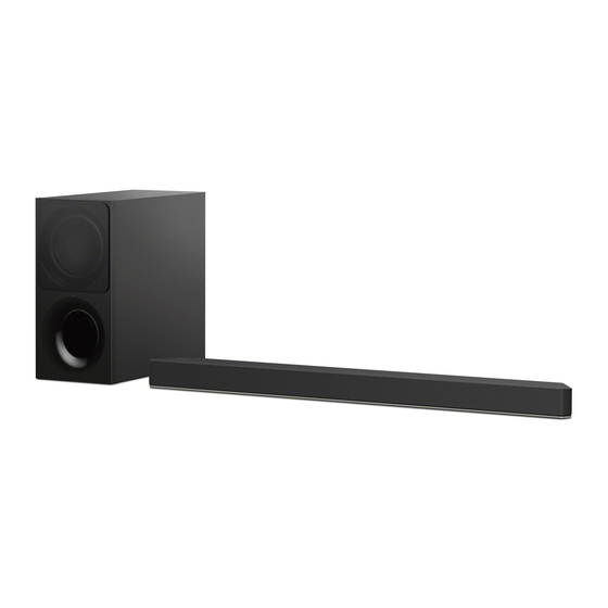
Photo: SA-X9000F
Front L/Front R speaker block section
Speaker system
Full Range speaker system, Acoustic
suspension
Speaker
40mm × 100mm (1 5/8 in. × 4 in) cone
type
General
Power requirements
120 V AC, 60 Hz (X9000F: US, CND)
220 V - 240 V AC, 50 Hz/60 Hz
(XF9000: AEP, UK)
Power consumption
On: 38W
[Bluetooth Standby] - [On]: Less than
2W
[Bluetooth Standby] - [Off]: Less than
0.5W
Dimensions* (approx.) (w/h/d)
930mm × 58mm × 85mm (36 5/8 in ×
2 3/8 in × 3 3/8 in)
*Not including projection portion
Mass (approx.)
2.5kg (5 33/64 lb)
ACTIVE SPEAKER SYSTEM
SA-X9000F/XF9000
US Model
Canadian Model
HT-X9000F/SA-X9000F
AEP Model
UK Model
HT-XF9000/SA-XF9000
Wireless Transmitter/
Receiver Section
Frequency band
2.4GHz (2.4000GHz - 2.4835GHz)
Modulation method
FHSS (Freq Hopping Spread Spectrum)
What's in the Box
equal to Premium High Speed HDMI
Cable with Ethernet) (1) (X9000F: US, CND)
Design and specifications are subject to
change without notice.
HT-X9000F/XF9000
SOUND BAR
SA-X9000F/XF9000
Advertisement
Table of Contents

Related Manuals for Sony HT-X9000F


Summary of Contents for Sony HT-X9000F
- Page 1 SA-X9000F/XF9000 SERVICE MANUAL US Model Canadian Model Ver. 1.0 2018.01 HT-X9000F/SA-X9000F AEP Model • All of the units included in the HT-X9000F UK Model (SA-X9000F/SA-WX9000F/Remote control) or HT-XF9000 (SA-XF9000/SA- HT-XF9000/SA-XF9000 WXF9000/Remote control) are required to confi rming operation of SA-X9000F/ XF9000.
- Page 2 Bluetooth Leakage current can be measured by any one of three methods. SIG, Inc. and any use of such marks by Sony 1. A commercial leakage tester, such as the Simpson 229 or RCA Corporation is under license. Other trademarks and trade names are those of WT-540A.
-
Page 3: Table Of Contents
HT-X9000F/XF9000 TABLE OF CONTENTS SERVICING NOTES DIAGRAMS ..........5-1. Block Diagram - HDMI Section - ........37 DISASSEMBLY 5-2. Block Diagram - MAIN Section - ........38 5-3. Block Diagram - AMP Section - ........39 2-1. Disassembly Flow ............ -
Page 4: Servicing Notes
XF9000: AEP 4-724-092-0[] ERATION XF9000: UK 4-724-093-0[] All of the units included in the HT-X9000F (SA-X9000F/SA- WX9000F/Remote control) or HT-XF9000 (SA-XF9000/SA- DESTINATION ABBREVIATIONS WXF9000/Remote control) are required to confi rming operation The following abbreviations for model destinations are used in this of SA-WX9000F/WXF9000. - Page 5 HT-X9000F/XF9000 SERIAL NUMBER WRITING WORK WHEN THE MAIN 8. Press the [V]/[v] buttons on the remote commander to select the “[EDIT]”, and press the [ ] button on the remote com- BOARD REPLACED mander. The cursor moves to the right serial number side.
- Page 6 HT-X9000F/XF9000 WIRELESS CONNECTION (LINK) WORK OF BAR SPEAK- What to do if only bar speaker or subwoofer are brought ER AND SUBWOOFER in for repair When the Bluetooth module of bar speaker or Bluetooth module of If only the bar speaker or subwoofer is brought in for repair situa-...
- Page 7 HT-X9000F/XF9000 RESETTING THE SYSTEM SPREADING OF COMPOUND When the IC6006 on the SK1 AMP board or the SK1 AMP board Press HOME. is replaced, spread the compound to the touching portion between The home menu appears on the TV the IC6006 and the heat sink.
-
Page 8: Disassembly
HT-X9000F/XF9000 SECTION 2 DISASSEMBLY • This set can be disassembled in the order shown below. 2-1. DISASSEMBLY FLOW 2-2. TOP/BOTTOM CABINET BLOCK-1 2-21. MAIN BOARD SERVICE POSITION (Page 9) (Page 26) Top cabinet block 2-3. TOP/BOTTOM CABINET BLOCK-2 (Page 10) Bottom cabinet block 2-9. -
Page 9: Top/Bottom Cabinet Block-1
HT-X9000F/XF9000 Note: Follow the disassembly procedure in the numerical order given. 2-2. TOP/BOTTOM CABINET BLOCK-1 • Continued on 2-3 (page 10). 1 eight screws (BVTP3 left side 2 two screws (BVTP3 front side top side 1 ten screws (BVTP3 top side... -
Page 10: Top/Bottom Cabinet Block-2
HT-X9000F/XF9000 2-3. TOP/BOTTOM CABINET BLOCK-2 soft cloth, etc. 1 Open the top cabinet block in the direction of the arrow. right side top cabinet block rear side 2 FFC (16P) (CN3004) left side (See Fig. A) 5 top cabinet block... -
Page 11: Sk1 Led Board
HT-X9000F/XF9000 2-4. SK1 LED BOARD Install the SK1 LED board on top of the speaker connection cable while holding down the connector with your fingers so that the speaker connection cable does not rise. Note 1: Check that the speaker connection cable is in the two grooves. -
Page 12: Speaker Connection Cable (L-Ch)
HT-X9000F/XF9000 2-5. SPEAKER CONNECTION CABLE (L-ch) 2 terminal (wide) [gray] 1 Draw the speaker connection 2 terminal (narrow) cable out of two grooves. [black] 1 Draw the speaker connection cable out of two grooves. left side 3 speaker connection cable [gray/black] (for L-ch) soft cloth, etc. -
Page 13: Speaker Connection Cable (R-Ch)
HT-X9000F/XF9000 2-6. SPEAKER CONNECTION CABLE (R-ch) top cabinet block left side 3 speaker connection cable 1 Draw the speaker connection cable out of two grooves. [red/black] (for R-ch) (See Fig. D) 2 terminal (narrow) front side [black] 2 terminal (wide) -
Page 14: Loudspeaker (L-Ch/R-Ch), Top Cabinet Assy
HT-X9000F/XF9000 2-7. LOUDSPEAKER (L-ch/R-ch), TOP CABINET ASSY boss 5 indicator (LED) left side hole boss Note 2: When installing the indicator (LED), align the two bosses and two holes. front side 1 two screws (BVTP3 SK1-TOUCH hole board hole boss... -
Page 15: Holder (Bt) Block
HT-X9000F/XF9000 2-9. HOLDER (BT) BLOCK FFC (18P) holder (BT) block CN1502 holder (BT) block terminal side CN1502 Pass the FFC (18P) underneath rear side the holder (BT) block. right side SK1-WS-CHUKEI board 2 two screws (BVTP3 2 screw (BVTP3 hole... -
Page 16: Sk1-Ws-Chukei Board
HT-X9000F/XF9000 2-10. SK1-WS-CHUKEI BOARD Gap. (Do not touch No gap. (Touch the shield main.) the shield main.) shield shield Gap. main main packing (CZ2) screw boss screw boss groove groove groove screw boss groove groove – – CN1501 CN702 left side... -
Page 17: Sk1 Ir Rep (2) Board
HT-X9000F/XF9000 2-11. SK1 IR REP (2) BOARD rear side catcher catcher catcher catcher SK1 IR REP (2) board – – left side right side CN1101 4 SK1 IR REP board cable connector (CN1101) top side 2 screw (BVTP3 5 SK1 IR REP (2) board Note: When installing the SK1 IR REP (2) board, align the hole and groove with the two bosses. -
Page 18: Main Chassis Block-1
HT-X9000F/XF9000 2-12. MAIN CHASSIS BLOCK-1 • Continued on 2-13 (page 19). top side left side 1 six screws (BVTP3 front side bottom cabinet block right side Note about installing the main chassis block IR repeater portion hole (SK1 IR REP (1) board) 3 Draw the IR repeater portion out of the hole in bottom cabinet. -
Page 19: Main Chassis Block-2
HT-X9000F/XF9000 2-13. MAIN CHASSIS BLOCK-2 1 four screws (BVTP3 2 insulator top hole Note: When installing the insulator top, align the four ribs and four holes. 1 screw (BVTP3 1 screw (BVTP3 1 screw (BVTP3 hole left side hole hole... -
Page 20: Power-Supply Cord
HT-X9000F/XF9000 2-14. POWER-SUPPLY CORD right side bottom cabinet block top side front side 1 Unlock. left side 2 cord bushing (FBS001) cord bushing (FBS001) power-supply cord to POWER board 80 ± 5 mm lock side 4 power-supply cord 3 Draw the power-supply cord out of the hole in bottom cabinet. -
Page 21: Main Board-1
HT-X9000F/XF9000 2-15. MAIN BOARD-1 • Continued on 2-16 (page 22). 2 shield main block Note: When installing the shield main block, align the hole and groove with the two ribs. 1 screw 1 two screws (BVTP3 (BVTP3 1 four screws... -
Page 22: Main Board-2
HT-X9000F/XF9000 2-16. MAIN BOARD-2 Note 1: When the MAIN board is replaced, be sure to refer to “SE- RIAL NUMBER WRITING WORK WHEN THE MAIN BOARD REPLACED” on page 5. 6 MAIN board block Note 2: When installing the MAIN board block, align the hole and groove with the two ribs. -
Page 23: Sk1 Ir Rep (1) Board
HT-X9000F/XF9000 2-17. SK1 IR REP (1) BOARD – – rear side 1 screw (BVTP3 1 three screws (BVTP3 screw (BVTP3 SK1 IR REP (1) board 7 screw hole (BVTP3 hole groove hole hole 8 SK1 IR REP (1) board 5 sheet radiation... -
Page 24: Sk1-Jack Board
HT-X9000F/XF9000 2-18. SK1-JACK BOARD 1 SK1-JACK board cable 2 two screws connector (CN1601) (BVTP3 2 screw left side (BVTP3 top side top side – – main chassis block front side right side Check that the jack and two connectors are installed on the holes of the chassis correctly. -
Page 25: Sk1 Amp Board
HT-X9000F/XF9000 2-19. SK1 AMP BOARD Note 1: When the SK1 AMP board is replaced, spread the compound to the touching portion between the IC6006 and the heat sink. 4 two screws (BVTP3 5 heatsink Note 2: When installing the heatsink, align boss the two bosses and two holes. -
Page 26: Power Board
HT-X9000F/XF9000 2-20. POWER BOARD 2 two screws (BVTP3 5 POWER board 2 screw Note: When installing the POWER board, (BVTP3 align the two ribs and two holes. 4 Draw the corner of POWER board out of the slit. 1 POWER board cable... -
Page 27: Test Mode
HT-X9000F/XF9000 SECTION 3 TEST MODE Button and LED position: Initial setting for demo mode: • Cannot power off by the [ ] button (both the main unit and the Button position remote commander). • The auto standby function becomes invalid. - Page 28 HT-X9000F/XF9000 DEMO RESET COPY BUILT-IN DEMO CONTENTS It can release the demo mode. It can overwrite the content to be playback with built-in demo sound source from the USB memory. Procedure: 1. In the demo mode state, touch the two buttons of the [...
- Page 29 HT-X9000F/XF9000 PANEL TEST SERVICE MODE Note: For the service mode work, need a TV monitor compatible with It can check the LED lighting state and key input. resolution “1920 × 1080 P” of video format. Checking procedure: Setting method of the service mode: 1.
- Page 30 HT-X9000F/XF9000 3. Service mode menu (Top Menu) This is the top menu of service mode. Each function is accessed from this screen. Operation: [V]/[v] Moves the cursor Moves to the screen of the item selected with the cursor Service diag [ver x.xx.xx]...
-
Page 31: Troubleshooting
HT-X9000F/XF9000 SECTION 4 TROUBLESHOOTING 1. Protection mode is occurs after turning the power on. When protection mode is occurs, all LEDs are fl ash for 5 seconds and turn the power off. Protection mode is occurs after turning the power on (all LEDs are flash for 5 seconds and turn the power off). - Page 32 HT-X9000F/XF9000 2. The video and audio of HDMI is not outputted The video and audio of HDMI is not outputted. The voltage of the following is about 3.3 V. The voltage of the following is 5.0 V. MAIN board: IC311 pin 3...
- Page 33 HT-X9000F/XF9000 3. The sound is not outputted The sound is not outputted. Check the signal path for being inputted to Entering the “BUILT-IN DEMO” the IC101 on the MAIN board, and then (touch the [ ] button for 3 replace the complete MAIN board.
- Page 34 HT-X9000F/XF9000 5. The sound is not outputted of ARC The sound is not outputted of ARC. Check the connection Change to the correct connection (connect the HDMI Connecting HDMI OUT (TV (ARC)) connector of the connector of the TV to the ARC cmpatible port).
- Page 35 HT-X9000F/XF9000 6. The subwoofer is not linked The subwoofer is not linked. If the subwoofer LED (on/standby indicator) does not light up even if you press the [1] button on the subwoofer, refer to “2. ON/STANDBY indicator does not light up (Power is not The subwoofer LED (on/standby indicator) is light up.
- Page 36 HT-X9000F/XF9000 MEMO...
-
Page 37: Diagrams
HT-X9000F/XF9000 SECTION 5 DIAGRAMS 5-1. BLOCK DIAGRAM - HDMI Section - SIGNAL PATH HDMI REPEATER : AUDIO (DIGITAL) IC5000 : VIDEO CN5004 CN5002 HDMI OUT IC101 (1/3) HDMI IN TV (ARC) DATA0+ 59 P2RX0P P1TX0P P21 HDMI_RX_0 HDMITX_CH0_P AJ15 P0RX0P... -
Page 38: Block Diagram - Main Section
HT-X9000F/XF9000 5-2. BLOCK DIAGRAM - MAIN Section - BLUETOOTH MODULE SPDIF_OUT I2S_SDI IC101 (2/3) BUFFER I2S_SCLK (BCK) IC1502 I2S_WS (LRCK) SD-RAM IC102 DQL0 – DQL7, CN1602 URXD1 AIROHA_RX RDQ0 – RDQ15 USB_DP_P1 DQU0 – DQU7 UTXD1 SWITCH AIROHA_TX USB_DM_P1 NCEB1... -
Page 39: Block Diagram - Amp Section
HT-X9000F/XF9000 5-3. BLOCK DIAGRAM - AMP Section - STREAM PROCESSOR IC6007 AMP_D0 (FL/FR), AMP_D2 (C/SW), LOW-PASS AMP_BCK, AMP_LRCK, AMP_MCK AMP_D2 (C/SW) >005B FILTER J6001 SDIN2 PWM_M_1 38 SUBWOFFER WIRED IC6010 (Page 38) CONNECTION WIRED_SWF_DET_MTK, WIRED_ON_MTK WIRED_ON_MTK >004B (Page 38) WIRED_SWF_DET_MTK... -
Page 40: Block Diagram - Panel/Power Supply Section
HT-X9000F/XF9000 5-4. BLOCK DIAGRAM - PANEL/POWER SUPPLY Section - POWER MANAGEMENT IC2302 DC/DC VCDT CONVERTER IC401 CHRLDO +3.3V AVDD28 M4 VA UNSW3.3V REGULATOR AVDD22 H15 VSYS IC402 VBAT_VSYS, VGP1_PMU N8 VGP1 VBAT_VPROC, VGP2_PMU L8 VGP2 IR_3V REGULATOR VBAT_VPA, IC101 (3/3) - Page 41 HT-X9000F/XF9000 THIS NOTE IS COMMON FOR PRINTED WIRING BOARDS AND SCHEMATIC DIAGRAMS. • Circuit Boards Location (In addition to this, the necessary note is printed in each block.) MAIN board For Printed Wiring Boards. For Schematic Diagrams. Note: Note: SK1 IR REP (1) board •...
-
Page 42: Printed Wiring Board - Main Board
HT-X9000F/XF9000 5-5. PRINTED WIRING BOARD - MAIN Board - • See page 41 for Circuit Boards Location. • : Uses unleaded solder. MAIN BOARD (SIDE A) (SHIELD) (BRACKET) (SHIELD) X3001 C5056 JL3026 CL5001 R5017 CL309 C307 R5011 D301 JL3027 JL3018... -
Page 43: Printed Wiring Boards - Sk1-Jack/Sk1-Ws-Chukei Boards
HT-X9000F/XF9000 5-6. PRINTED WIRING BOARDS - SK1-JACK/SK1-WS-CHUKEI Boards - • See page 41 for Circuit Boards Location. • : Uses unleaded solder. SK1-JACK BOARD SK1-JACK BOARD SK1-WS-CHUKEI BOARD (SIDE A) SK1-WS-CHUKEI BOARD (SIDE B) (SIDE A) (SIDE B) JL1604 IC1502... -
Page 44: Printed Wiring Board - Sk1 Amp Board
HT-X9000F/XF9000 5-8. PRINTED WIRING BOARD - SK1 AMP Board - • See page 41 for Circuit Boards Location. • : Uses unleaded solder. SK1 AMP BOARD (SIDE A) J6001 SUBWOOFER (Page 42) WIRED CONNECTION MAIN BOARD >05P CN701 FFC4 LN6005... -
Page 45: Schematic Diagram - Sk1 Amp Board
HT-X9000F/XF9000 5-9. SCHEMATIC DIAGRAM - SK1 AMP Board - • See page 48 for Waveforms. • See page 48 for IC Block Diagrams. SK1 AMP BOARD LN6002 CL6003 (CHASSIS) LN6004 R6061 R6024 CL6007 100k C6042 C6053 C6056 C6065 (CHASSIS) 1000p... -
Page 46: Printed Wiring Board - Power Board
HT-X9000F/XF9000 5-10. PRINTED WIRING BOARD - POWER Board - • See page 41 for Circuit Boards Location. • : Uses unleaded solder. POWER BOARD IC902 JR901 JL908 R939 Q908 R938 R920 R927 C905 JL903 R901 R922 R930 PH901 C926 R940... -
Page 47: Schematic Diagram - Power Board
HT-X9000F/XF9000 5-11. SCHEMATIC DIAGRAM - POWER Board - • See page 48 for IC Block Diagrams. POWER BOARD ET902 JL910 ET901 JL905 (CHASSIS) CN902 JL904 JL911 (CHASSIS) (Page 45) PGND C924 0.01 >01S PGND C910 C906 D909 LF901 CN901 F901 0.0022... - Page 48 HT-X9000F/XF9000 • Waveforms • IC Block Diagrams – SK1-WS-CHUKEI Board – – SK1-WS-CHUKEI Board – IC1501 MM3411A33URE IC1502 4 CE 1 BIAS VOLTAGE – REFERENCE 3.3 Vp-p 324 ns CURRENT LIMIT VOUT 1 V/DIV, 200 ns/DIV GND 2 – SK1 AMP Board –...
- Page 49 HT-X9000F/XF9000 IC6006 TAS5614LA-S GVDD_AB 1 BST_A BST_B VDD 2 OC_ADJ 3 RESET 4 OUT_A ANALOG PWM & TIMING GATE- LOOP FILTER CONTROL DRIVE INPUT_A 5 – OUT_A RECEIVER PVDD_AB PVDD_AB PVDD_AB INPUT_B 6 ANALOG PWM & TIMING GATE- RECEIVER OUT_B...
- Page 50 HT-X9000F/XF9000 – POWER Board – IC901 BM1Q002FJ-E2 STARTER 13.0V/ 1SHOT UVLO 4.0V 12V CLAMP 13.5V/ VREF 8.7V REGULATOR CIRCUIT 8.2V TIME 100mV /200mV 27.5V COMP. TRIGGER DETECT VREF LOGIC DRIVER ZT BLANKING MAX FREQUENCY CONTROL BURST COMP. DELAY STOP TIMER TIMER 0.50V...
-
Page 51: Exploded Views
HT-X9000F/XF9000 SECTION 6 EXPLODED VIEWS Note: • -XX and -X mean standardized parts, so • The mechanical parts with no reference The components identifi ed by mark 0 they may have some difference from the number in the exploded views are not sup- or dotted line with mark 0 are critical for original one. -
Page 52: Top Cabinet Section
HT-X9000F/XF9000 6-2. TOP CABINET SECTION left side front side top side rear side right side Ref. No. Part No. Description Remark Ref. No. Part No. Description Remark A-2186-967-A SK1 LED BOARD, COMPLETE 1-859-248-11 LOUDSPEAKER (35X93 mm) (Front L-ch) FFC1 1-912-605-11... -
Page 53: Bottom Cabinet Section
HT-X9000F/XF9000 6-3. BOTTOM CABINET SECTION top side MAIN board section rear side left side front side right side Note: When the bluetooth module (Ref. No. BT1) is replaced, be sure to refer to “WIRELESS CONNECTION (LINK) WORK OF BAR SPEAKER AND SUBWOOFER” on page 6. -
Page 54: Main Board Section
HT-X9000F/XF9000 6-4. MAIN BOARD SECTION top side Note 1: The parts for repair of the radiation sheet (Ref. No. 154, 155) are larger than the radiation sheet before replacement. When replacing the radiation sheet (Ref. No. 154, 155), make sure to cut it to the sizes below. -
Page 55: Sk1 Amp Board Section
HT-X9000F/XF9000 6-5. SK1 AMP BOARD SECTION top side Note 1: The parts for repair of the radiation sheet (Ref. No. 201) is larger than the radiation sheet before replacement. When replacing the radiation sheet (Ref. No. 201), make sure to cut it to the sizes below. -
Page 56: Power Board Section
HT-X9000F/XF9000 6-6. POWER BOARD SECTION top side left side rear side front side right side Ref. No. Part No. Description Remark Ref. No. Part No. Description Remark A-2186-843-A POWER BOARD, COMPLETE 7-685-646-71 SCREW +BVTP 3X8 TYPE2 IT-3... -
Page 57: Electrical Parts List
8-719-083-71 DIODE UDZSUSTE-1730B 0 D905 6-503-058-01 DIODE DB2J31700L < VARISTOR > 0 D908 6-502-961-01 DIODE DA2J10100L 0 D910 6-503-775-01 DIODE CRH02 (T5R, SONY, XM) 0 VR901 1-811-165-31 VARISTOR (TVR10471-D) ************************************************************* 0 D911 6-503-900-01 DIODE SARS05 D913 6-501-849-01 DIODE FMX-22SL A-2186-964-A... - Page 58 HT-X9000F/XF9000 SK1 AMP SK1 IR REP (1) SK1 IR REP (2) SK1-JACK SK1 LED SK1-TOUCH SK1-WS-CHUKEI Ref. No. Part No. Description Remark Ref. No. Part No. Description Remark < FUSE > < JACK > 0 F6001 1-523-395-11 FUSE (5 A/32 V)
- Page 59 HT-X9000F/XF9000 Ref. No. Part No. Description Remark ACCESSORIES ************ 4-725-865-12 MANUAL, INSTRUCTION (Operating Instructions) (ENGLISH, SPANISH, FRENCH) (X9000F: US, CND) 4-725-865-21 MANUAL, INSTRUCTION (Operating Instructions) (ENGLISH) (XF9000: UK) 4-725-865-31 MANUAL, INSTRUCTION (Operating Instructions) (FRENCH, SPANISH, DUTCH) (XF9000: AEP) 4-725-865-41 MANUAL, INSTRUCTION (Operating Instructions)
- Page 60 HT-X9000F/XF9000 REVISION HISTORY Ver. Date Description of Revision 2018.01 How to search for a contact point of signal lines or the like in DIAGRAMS SECTION If a contact point of a BLOCK DIAGRAM, PRINTED WIRING BOARD or SCHEMATIC DIAGRAM is shown in a different page, use the PDF fi...