Table of Contents
Advertisement
Quick Links
Advertisement
Table of Contents

Related Manuals for Kenwood CS-6040


Summary of Contents for Kenwood CS-6040
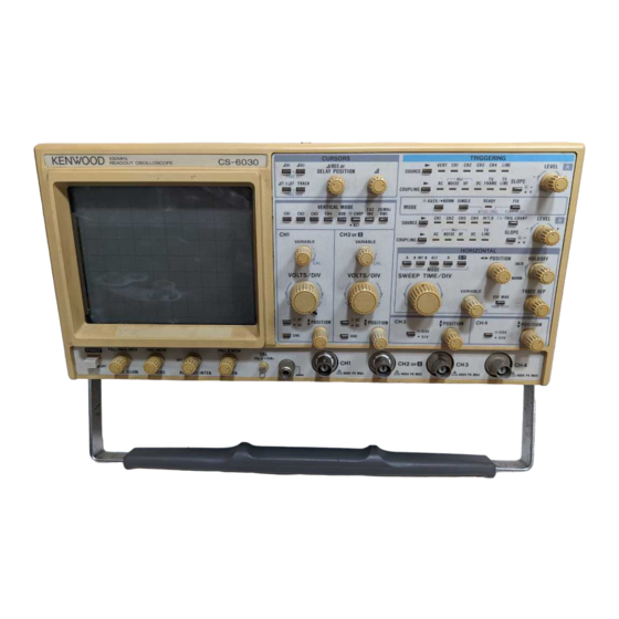
- Page 1 150MHz QUAD T R A C E R E A D O U T O S C I L L O S C O P E CS-6040 100MHz QUAD T R A C E R E A D O U T O S C I L L O S C O P E...
-
Page 2: Table Of Contents
S A F E T Y Use the Proper Power Cord Symbol in This Manual Use only the power cord and connector specified for your This symbol indicates where applicable cautionary or product. other imformation is to be found. Use the Proper Fuse Power Source To avoid fire hazard, use a fuse of the correct type. -
Page 3: Features
FEATURES The C S - 6 0 4 0 [ C S - 6 0 3 0 ] is a four-channel, 10-trace oscil- 6. Free vertical mode selection of C H 1 to C H 4 and A D D loscope with a readout function (calendar provided) cover- offers easy observation of waveform composed of a lot of signal components. -
Page 4: Specifications
SPECIFICATIONS C S - 6 0 4 0 C S - 6 0 3 0 1 5 0 mm rectangular with internal graticule C R T 17 k V Acceleration Voltage 2 0 k V 8 x 10 div (1 div = 10 mm) Display Area V E R T I C A L A X I S... - Page 5 C S - 6 0 3 0 C S - 6 0 4 0 S W E E P A s w e e p T y p e T y p e T y p e T y p e T y p e B s w e e p waveform is displayed a s an intensified portion of the A s w e e p .
- Page 6 C S - 6 0 3 0 C S - 6 0 4 0 MINIMUM S Y N C MINIMUM S Y N C Trigger Sensitivity Trigger Sensitivity Trigger Sensitivity Trigger Sensitivity Trigger Sensitivity Trigger Sensitivity Trigger Sensitivity F R E Q U E N C Y R A N G E COUPLING F R E Q U E N C Y R A N G E A M P L I T U D E A M P L I T U D E...
- Page 7 C S - 6 0 4 0 C S - 6 0 3 0 P R O G R A M M O D E 2 0 steps x 5 blocks Programming capacity A V 1 , AV2, AT, MAT, T R A C K I N G C U R S O R MODE C U R S O R S...
-
Page 8: Precautions
PRECAUTIONS 5. A l w a y s connect a cable from the earth ground (GND) S A F E T Y jack of the oscilloscope to the chassis of the equipment Before connecting the instrument to the power source, care- under test. - Page 9 Factory installed Plug configuration Power cord and plug type Line cord plug fuse instrument fuse North American 1.2 A , 2 5 0 V 1 2 0 v o l t / 6 0 Hz F a s t blow None Rated 1 5 amp 6 x 3 0 mm...
-
Page 10: C O N T R O L S A N D I N D I C A T O R
CONTROLS AND INDICATORS FRONT PANEL Fig. 2 © POWER Switch © C A L 1 V p - p « 1 kHz Terminal Outputs 1 kHz positive square w a v e of 1.0 Vp-p for Depressing this s w i t c h supplies power. Another press- calibration. - Page 11 C H 3 : The channel-3 input signal is displayed © CH1 A C - D C Switch on the C R T . Selects coupling of the channel-1 vertical axis input sig- C H 4 : The channel-4 input signal is displayed nal.
- Page 12 Fig. 3 (§) CH4 T POSITION Control In the 4 V 3 cursor measurement, a value calculat- Adjusts vertical position of channel-4 waveform dis- ed according to setting of the C H S 0 . 5 V / 0 . 1 V is played on the C R T .
- Page 13 NOTE: If X - Y of the HORIZONTAL MODE switches T R A C K : © is selected, A V 2 is used for voltage When the T R A C K I N G s w i t c h is pressed, the LED difference and voltage ratio measurement goes on and the machine enters the T R A C K I N G of the X-axis.
- Page 14 Fig. 4 A L T : Displays A s w e e p and B s w e e p (delayed • POSITION Control sweep) alternately. Intensity of a B s w e e p Moves waveform in the horizontal direction for horizon- portion displayed on A sweep waveform is in- tal position adjustment.
- Page 15 ed, low-frequency signals can be triggered © A TRIGGERING S O U R C E (A SOURCE) Selector Switch stably. and LEDs The A sweep trigger signal is applied to the Selects a trigger source of A s w e e p . Every press of the trigger circuit by DC coupling, enabling •...
- Page 16 .v-.U"; -*-^.a:.~¥.?' Fig. 5 A C : T h e B s w e e p trigger signal is applied to the C H 2 : B s w e e p is triggered by channel-2 vertical axis trigger circuit by A C coupling. DC compo- input signal.
- Page 17 © TRIGGERING MODE (TRIG MODE) Selector Switches and LEDs S w i t c h e s and L E D s used to select the trigger operation modes. A U T O / N O R M : Pressing the s w i t c h turns on the LED and selects the automatic mode.
-
Page 18: Rear Panel 1
REAR PANEL Fig. 6 (49) Z A X I S INPUT Jack (§) A C Connector Input of the external intensity modulation. Positive vol- Connector for A C power supply. tage reduces intensity, and TTL-level voltage activates intensity modulation. © Cable Hooks Used to roll up the A C cable for transportation or (§) -
Page 19: R E A D O U T D I S P L A
READOUT DISPLAY [1] DISPLAY POSITIONS The calendar, each scale factor, cursor measurement values, etc. are displayed in the following positions of the C R T . C u r s o r M e a s u r e m e n t V a l u e / C u r s o r M e a s u r e m e n t M o d e /... - Page 20 5 CH2 Scale Factor Displays the channel-2 vertical axis sensitivity for 1 div. In the U N C A L condition, a " > " is displayed before the channel-2 vertical axis sensitivity. If channel-2 is grounded, however, a " jfr " mark is displayed but no "...
-
Page 21: O P E R A T I N G I N S T R U C T I O N
OPERATING INSTRUCTIONS INITIAL STARTING PROCEDURE Prior to turning on power, set each control as s h o w n above Prior to using the probe, read through the manual attached in advance. Setting of other s w i t c h e s and controls in the to it as well a s "... - Page 22 NORMAL with noises, this mode provides stable triggering. The normal s w e e p mode allows the trigger point to be set with the L E V E L and S L O P E , like the A U T O H F R E J s w e e p mode.
- Page 23 1 4 ) LEVEL Controls and SLOPE Switches Trigger point of waveform is adjusted with the L E V E L L E V E L controls and S L O P E s w i t c h e s . Fig. 11 s h o w s the set- ( 1 ) ting relationship between the L E V E L and SLOPE for trig- ger point adjustment.
-
Page 24: Sweep Magnification 2
[3] DELAYED SWEEP (6) HOLDOFF Control When observing signals containing pulses at different The A sweep and B sweep are used for delayed sweep mag- intervals in spite of constant repetition of pulses, im- nification. proper adjustment of the HOLDOFF control (§) results in doubled waveform display. - Page 25 By setting the H O R I Z O N T A L MODE s w i t c h e s (§) to 3 . TRIG COUNT Switch B, the A s w e e p waveform disappears, and the The TRIG COUNT switch is conveniently used for delayed intensity-modulation part on the A s w e e p trace line sweep of signals w h o s e number of pulses is already-...
-
Page 26: Readout Operation 2
Example: Measurement at count value of 1 0 0 A s w e e p t r a c e line a n d i n t e n s i t y - m o d u l a t i o n p a r t A L E V E L S e t t i n g... - Page 27 2. Cursor Measurement to the edge of the monitor, movement cannot pro- 4 V 1 : By selecting C H 1 of the V E R T I C A L MODE © and ceed any further. Using the A control, zlcursor can V 1 of the C U R S O R S ©...
-
Page 28: Tv Count 2
In case A INT B, A L T , or X - Y of the H O R I Z O N T A L When the last line of a given field is reached, the MODE s w i t c h e s is selected machine returns to the first line of that field. - Page 29 step not set to " S K I P " , and the panel conditions will be set up according to the data contained in that step. After R E A D O U T and setting up of programmed panel conditions, the panel settings can be changed manually as desired.
-
Page 30: Probe Compensation
APPLICATIONS P R O B E C O M P E N S A T I O N Adjust the •< • POSITION to bring the point of the waveform to be measured to t h e center vertical For accurate measurement, the probe should be compen- graduation line. - Page 31 A l i g n t o c e n t e r v e r t i c a l g r a d u a t i o n line w i t h <« is- P O S I T I O N c o n t r o l T w o p o i n t s t o b e m e a s u r e d M e a s u r e d v a l u e C u r s o r...
-
Page 32: Elimination Of Undesired Signal Components 3
4. CURSOR MEASUREMENT OF VOLTAGE 3. ELIMINATION OF UNDESIRED SIGNAL COM- RATIO PONENTS The following describes measurement of overshoot of The A D D mode eliminates undesired signal components and square w a v e s , etc. displays necessary components only. (See Fig. 30.) Apply the signal to be measured to the INPUT connec- Apply the signal containing an undesired component to tor. -
Page 33: Time Difference Measurement 3
A l i g n t o v e r t i c a l g r a d u a t i o n 6. TIME DIFFERENCE MEASUREMENT line w i t h + • P O S I T I O N Normal Procedures The following describes normal procedures for measuring time difference between t w o signal synchronized to each... -
Page 34: Pulse Width Measurement 3
(2) Cursor Measurement Procedures Display the waveform to be measured in an easy-to- A l i g n t o v e r t i c a l g r a d u a t i o n l i n e w i t h * * •... - Page 35 Adjust the 1 0 % point to a vertical graduation line with C e n t e r 9 0 % p o i n t w i t h POSITION control. Measure the horizontal dis- < • P O S I T I O N t o r e a d D tance between the 1 0 % and 9 0 % points.
-
Page 36: Phase Difference Measurement
9. PHASE DIFFERENCE MEASUREMENT Phase difference = Horizontal distance of n e w s w e e p range (div) | 1 ) Normal Procedures x 4 5 ° / d i v T h e following describes the normal procedures for measur- n e w S W E E P T I M E / D I V setting ing phase difference of t w o signals (sine w a v e , for e x a m - original S W E E P T I M E / D I V setting... -
Page 37: Time Ratio Measurement
M e a s u r e d v a l u e - 11. FREQUENCY MEASUREMENT (1) Normal Procedures Since frequency is a reciprocal of a period, it can be deter- mined by measuring time of one cycle. Measure time of one cycle according to the procedures mentioned in section 5 T I M E M E A S U R E M E N T . -
Page 38: Relative Measurement
* Vertical Sensitivity Setting of the relative vertical sensitivity using a reference signal amplitude Apply the reference signal to the input connector. A d - just each control for normal s w e e p display. Adjust the V O L T S / D I V and V A R I A B L E controls accurately so that the signal amplitude coincides w i t h a f e w divisions of the graduation line. - Page 39 [EXAMPLE] In the example s h o w n in Fig. 4 8 , the V O L T S / D I V set- R e f e r e n c e A d j u s t e d r e f e r e n c e s i g n a l ting is 1 V/div and the reference signal is 2 V r m s .
-
Page 40: Application Of X - Y Operation 4
13. APPLICATION OF X-Y OPERATION * Phase Measurement The X - Y operation can be used for phase measurement. Typical application covers measurement of phase distortion in circuits designed to produce a certain phase shift and au- dio amplifiers. Distortion amplitude can be measured at the same time. Phase measurement is made as follows: a m p l i t u d e N o p h a s e... -
Page 41: Pulse Jitter Measurement 4
14. PULSE JITTER MEASUREMENT Pulse jitter can be measured as follows: (1) Normal Procedures Apply the signal to the input connector. Select the chan- R E F c u r s o r M e a s u r e d v a l u e - nel to be used w i t h the V E R T I C A L MODE. -
Page 42: Measurement Of Delayed Sweep Time
16. MEASUREMENT OF DELAYED SWEEP TIME Using the B s w e e p operation, time can be measured a c - I n t e n s i t y - m o d u l a t i o n p a r t curately. -
Page 43: Pulse Width Measurement Using Delayed S W E E
17. PULSE WIDTH MEASUREMENT USING DELAYED SWEEP High-accuracy pulse width can be measured in the same manner as the time measurement. Apply the pulse signal to the input connector. Select the channel to be used with the V E R T I C A L MODE. Adjust each control for normal s w e e p display. -
Page 44: Rise And Fall Time Measurement Using Delayed Sweep 4
R e a d m e a s u r e m e n t s w h e n A F T . D B s w e e p t r a c e s © a n d © a r e a d j u s t e d t o s a m e p o s i t i o n - 2 n d m e a s u r e m e n t... -
Page 45: 3 . U S E Of Trigger Counter: Procedure And Example 4
setting © C o m p a r i s o n s i g n a l If A L T of the H O R I Z O N T A L MODE s w i t c h e s is selected in R e f e r e n c e s i g n a l s e t t i n g M e a s u r e m e n t the above example, traces of the main s w e e p and delayed... - Page 46 If the counter value at this moment is read, it can be used to determine how many pulses the C H 2 signal has with respect to one cycle of the C H 2 signal. 24. COUNTER APPLICATIONS (1) Observation of TV Signals Apply the signal to the input connector.
- Page 47 8) Press PROG S T E P to write the set conditions to memory. The Program Step Number will be " 3 " . 9 ) Press PROG RUN to enable the S K I P mode, then press PROG S T E P and write the set conditions to memory.
-
Page 48: Adjustment
ADJUSTMENT HOW TO CHANGE SETTING OF READOUT Example: Correction of Calendar and Clock Display. CALENDAR AND CLOCK © Make " M o n t h " display f l a s h . To turn on and off the calendar and clock display or change "... - Page 49 NOTE: After operation (1) or during correction of the calendar and clock display, s w i t c h e s and con- trols on the panel cannot function properly. If switch or control operation is required, complete correction. NOTE: B e w a r e of the following instructions w h e n cor- recting the calendar and clock display: ©...
-
Page 50: Maintenance
MAINTENANCE A Caution : Read this page carefully to keep your safety. FOR ELECTRIC S H O C K PROTECTION: B E SURE TO DISCONNECT THE POWER CABLE FROM THE SOCKET BEFORE CONDUCTING THE FOLLOWING OPERATION. CHANGING THE SUPPLY VOLTAGE R E P L A C I N G T H E F U S E in case the fuse has blown, locate the c a u s e . -
Page 51: A C C E S S O R I E S
A C C E S S O R I E S STANDARD A C C E S S O R I E S INCLUDED OPTIONAL A C C E S S O R I E S Probe Pouch ( M C - 7 8 ) Y 8 7 - 1 6 0 0 - 0 0 Probe (PC-31) (for R E A D O U T ) W 0 3 - 2 3 0 1 - 0 5... - Page 52 > A product of K E N W O O D C O R P O R A T I O N 2-5, 1-chome, Shibuya, Shibuya-ku, Tokyo 150, J a p a n...