Advertisement
Quick Links
Advertisement

Related Manuals for Kenwood CS-1575 A


Summary of Contents for Kenwood CS-1575 A
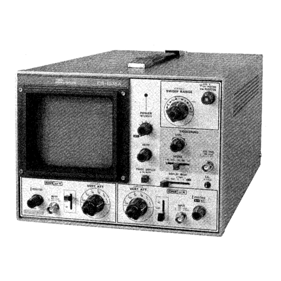
- Page 1 C S - 1 5 7 5 A (DUAL TRACE OSCILLOSCOPE) INSTRUCTION MANUAL...
- Page 2 SAFETY Symbol in T h i s Manual Use the Proper Power Cord This symbol indicates where applicable cautionary or Use only the power cord and connector specified for your other information is to be found. product. Power Source Use the Proper Fuse This equipment operates from a power source that does T o avoid fire hazard, use a fuse of the correct type, not apply more than 2 5 0 V rms between the supply con-...
- Page 3 FEATURES 1 . High sensitivity of 1 0 mV/div or more and wide band- to permit automatic selection. width of 5 MHz ( - 3 dB). 7. X - Y selection allows C H 1 amplifier to be used as Y axis 2.
- Page 4 SPECIFICATIONS Frequency response : DIMENSIONS DC : D C to 1 MHz ( - 3 dB), Width : 2 6 0 m m ( 2 6 0 mm) DC to 1.5 MHz ( - 6 dB) Height : 1 9 0 m m ( 2 1 4 mm) . A C : 5 Hz to 1 MHz ( - 3 dB), Depth :...
- Page 5 PREPARATION FOR USE S A F E T Y EQUIPMENT PROTECTION Before connecting the instrument to a power source, care- Never allow a small spot of high brilliance to remain s t a - fully read the following information, then verify that the tionary on the screen for more than a f e w seconds.
- Page 6 CONTROLS AND INDICATORS VARIABLE Front Panel: © posiTION Attenuator for fine control of CH1 (or Y ) . This control adjusts vertical position during C H 1 or X - Y operation. A right turn will shift the waveform upward. ®...
- Page 7 ® S O U R C E © VARIABLE Trigger signal selector with the following functions, Used for fine adjustment of s w e e p time. LINE : Synchronized to the power supply frequency. D U A L : Source is automatically selected according to ©...
- Page 8 REAR PANEL: © A C V O L T A G E SELECTOR Before operating, set this selector to the A C power voltage ® C R T cower used. Used for adjustment of trace angle. Refer to "Maintenance". ® POWER CONNECTOR ©...
- Page 9 OPERATION PRELIMINARY OPERATION When operating the oscilloscope, refer to panel controls and their function. Before the power s w i t c h is turned on, set the con- trols a s follows. oscilloscope m a y be checked by feeding input from OPERATING PROCEDURES C A L 0 .
- Page 10 accurate triggering can be achieved ( j j ) E X T S L O P E " + " R A N G E without regard to the input signal fed to INPUTs (3) and D I R E C T I O N L E V E L - T R I G G E R S I G N A L ( G A T E S I G N A L ) D I R E C T I O N...
- Page 11 Fig. 8 s h o w s Lissajous' figures when 1 kHz sine w a v e s of WAVEFORM SETTING WITH PHASE DISPLAY 0 ° , 9 0 ° and 1 8 0 ° of phase difference are applied to X and AND CONTROL KNOBS: Y axes.
- Page 12 [ E X A M P L E 3] [EXAMPLE 2] \ • • . • Fig. 1 3 s h o w s the waveform when D I S P L A Y MODE is set In Example 2 , if the positions of C H 1 and C H 2 are reversed, to D U A L - V , P H A S E D I S P L A Y to ON, and C H I and C H 2 are the waveforms displayed are as s h o w n in Fig.
- Page 13 APPLICATIONS APPLICATIONS OF PHASE DISPLAY Adjustment of Head Azimuth of Tape Deck Use a standard tape ( 4 0 0 Hz or 3 1 5 Hz) and s e t the By using the method shown in Fig, 1 2 , audio systems can be checked and t e s t e d .
- Page 14 position. Connect the output of the microphone to C H 1 T e s t of Propagation Characteristic of Listening Room In a listening room t h e sound, from the speaker is some- and a part of the output of the signal generator to C H 2 to compare the levels.
- Page 15 Wave form Judgement Trouble Remarks No phase shift. No amplitude distortion. The same signal is applied distortion bet- to CH1 and C H 2 . ween channels. * Incorrect input con- nection (signal and 1 8 0 ° out of phase. earth connected in Locate the cause of trou- No amplitude distor-...
- Page 16 response check of an amplifier should be made using a sine AMPLIFIER SQUARE WAVE T E S T w a v e signal. This is especially important in an limited band- Introduction pass amplifier such a s a voice amplifier. T h e square w a v e A square w a v e generator and oscilloscope can be used to signal provides a quick check of amplifier performance and display various types of distortion present in electric cir-...
- Page 17 A s a rule of thumb, it can be safely said that a square w a v e Analysis of Waveforms can be used to reveal response and phase relationships up The short rise time which occurs at the beginning of the to the 15th or 2 0 t h odd harmonic or up to approximately half-cycle is created by the in-phase s u m of the medium 4 0 times the fundamental of the square w a v e .
- Page 18 If the amplifier were such a s to only depress the low fre- quency components in the square w a v e , a curve similar to Fig. 2 5 would be obtained. However, -reduction amplitude of the components is usually caused by a reac- tive element, causing, in turn, .a phase shift .of the com- ponents, .producing the tilt a s s h o w n in Fig.
- Page 19 Fig. 3 0 indicates high frequency boost in an amplifier that the energy for oscillation in t h e resonant, network in accompanied by a lightly damped " s h o c k " transient. the amplifier is reasonably damped, then a. single cycle In this case, w h e n the sudden transition in the square wave, transient oscillation may be produced a s illustrated - in Fig.
- Page 20 V A R I A B L E control is adjusted as required to provide a com- OTHER APPLICATIONS " plete cycle of the input waveform displayed on 8 div Amplifier Phase Shift Measurement . - horizontally,, while the waveform height is set to 2 div. The In the square w a v e testing section of this manual, square 8 div.
- Page 21 Frequency measurement (1) Connect the sine w a v e of known frequency to the C H 2 input of the oscilloscope and set the D I S P L A Y MODE s w i t c h to X - Y . 12) Connect the C H 1 to the signal to be measured.
- Page 22 A C C E S S O R I E S S T A N D A R D A C C E S S O R I E S I N C L U D E D Instruction Manual .
- Page 24 A product of K E N W O O D C O R P O R A T I O N 17-5, 2-chome, S h i b u y a , S h i b u y a - k u , Tokyo 150, Japan P R I N T E D IN J A P A N B 5 0 - 7 5 4 9 - 2 0 ( T ) 9 1 / 1 2 11 10 9 8 7 6 5 4 3 2...