ABB REB500 Operation Manual
Hide thumbs
Also See for REB500:
- Technical manual (194 pages) ,
- Operation manual (110 pages) ,
- Applications manual (108 pages)

Related Manuals for ABB REB500


Summary of Contents for ABB REB500
- Page 1 REB500 Substation Automation Products Distributed busbar protection REB500 Operation Manual Datasheet.Directory...
- Page 3 Document ID: 1MRK 500 124-UEN Issued: March 2016 Revision: - Product version: 8.2 © Copyright 2016 ABB. All rights reserved...
- Page 4 Copyright This document and parts thereof must not be reproduced or copied without written permission from ABB, and the contents thereof must not be imparted to a third party, nor used for any unauthorized purpose. The software and hardware described in this document is furnished under a license and may be used or disclosed only in accordance with the terms of such license.
- Page 5 In case any errors are detected, the reader is kindly requested to notify the manufacturer. Other than under explicit contractual commitments, in no event shall ABB be responsible or liable for any loss or damage resulting from the use of this manual or the application of the equipment.
- Page 6 (EMC Directive 2004/108/EC) and concerning electrical equipment for use within specified voltage limits (Low-voltage directive 2006/95/EC). This conformity is the result of tests conducted by ABB in accordance with the product standards EN 50263 and EN 60255-26 for the EMC directive, and with the product standards EN 60255-1 and EN 60255-27 for the low voltage directive.
- Page 7 Safety information The busbar protection system REB500 corresponds to the latest practices and guidelines and complies with the recognized safety rules. Nevertheless, care must always be taken to avoid danger. Only use the busbar protection system when it is in perfect working order and in strict accordance with these operating instructions.
- Page 8 Take care never to open the secondary circuits of CTs conducting current. There is a danger of contact with live parts when opening REB500 cubicle doors. Electrostatic discharge can destroy components in the equipment. Other safety instructions pertaining to particular operations are...
-
Page 9: Table Of Contents
Switchgear objects ..............23 3.5.6 Protection zone circuit-breakers ..........25 3.5.7 Disturbance recorder..............25 3.5.8 Event list .................. 29 3.5.9 Security event list ..............32 3.5.10 Reset latching relays ..............32 Configuration menu ............... 33 Operation Manual Distributed busbar protection REB500... - Page 10 4.3.1 Introduction ................73 4.3.2 Viewing data on the local HMI ...........73 4.3.3 Protection Indicator LEDs............74 4.3.4 LED signals ................74 4.3.5 LCD backlight ................75 4.3.6 Buttons ..................75 4.3.7 Menu structure ................76 Alarms ...................79 Trips ....................81 Operation Manual Distributed busbar protection REB500...
- Page 11 Faults during startup ..............86 6.2.3 Alarm and Event list entries ............86 6.2.4 Optical fiber connections faults ..........87 6.2.5 Electrical connection faults ............88 Diagnostic (DIA) system - error handling ........88 Operation Manual Distributed busbar protection REB500...
-
Page 13: Section 1 Introduction
The operator must be trained in and have a basic knowledge of how to operate protection equipment. The manual contains terms and expressions commonly used to describe this kind of equipment. Product documentation For an introduction into REB500, it is recommended to study the Product Guide and/or the Application Manual. Manual Document number... -
Page 14: Symbols And Conventions
Abbreviations and acronyms in this manual are spelled out in the glossary. The glossary also contains definitions of important terms. • Push button navigation in the LHMI menu structure is presented by using the push button icons, e.g.: To navigate the options, use Operation Manual Distributed busbar protection REB500... -
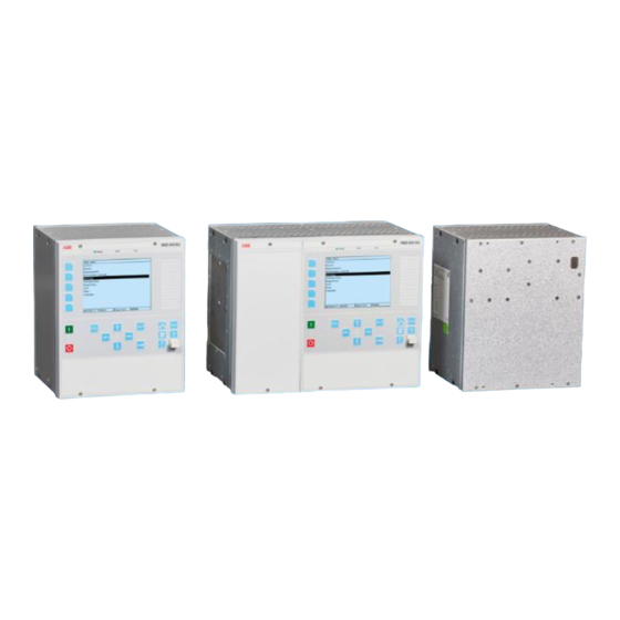
Page 15: Section 2 System Overview
Section 2 1MRK 500 124-UEN System Overview Section 2 System Overview Figure 1 System overview Operation Manual Distributed busbar protection REB500... - Page 16 1MRK 500 124-UEN System Overview The digital busbar protection REB500 is divided into several hardware units. Bay units measure the line and bus-tie breaker currents and may be installed close to the respective CTs. They communicate with the central unit via a process bus. The central unit processes the current signals measured by the bay units and distributes the tripping signals back to the bay units in the event of an internal busbar fault.
-
Page 17: Section 3 Hmi500
HMI500 is a convenient human-machine interface which permits the operator to view measurements and statuses, to set protection functions, to configure the system, to download the latter data to REB500, and to control the disturbance recorder and event memory integrated in the system. -
Page 18: Basic Setup
Depending on the power system configuration and the options configured while engineering your system, certain menus may be missing or the display appears different. The first screen to appear after starting the operator program is the “System login” dialog: Operation Manual Distributed busbar protection REB500... - Page 19 When the HMI500 software establishes communication with a REB500 system initially user must enter a password. For details about security management, passwords and security options refer to the “Security Deployment Guideline”.
-
Page 20: Window Structure
Details. 3.3.5 Main window The title bar is at the top of the main program window and displays the station name. The menu bar is located immediately below the title bar. Operation Manual Distributed busbar protection REB500... - Page 21 Simulation All the functions can be executed without being connected to a protection device. Random values are generated when viewing protection unit data, e.g. event lists or measurements. Simulated faults can also be viewed. Operation Manual Distributed busbar protection REB500...
-
Page 22: File Menu
Exit Terminates the program; displays a warning if there are changes that have not been saved. You then have the choice of saving or discarding them. Operation Manual Distributed busbar protection REB500... -
Page 23: Download To Protection System
PC for the procedure to be presented correctly. The procedure can be interrupted by the user as far as “Archive data in the protection system”. Operation Manual Distributed busbar protection REB500... -
Page 24: Compare
The auxiliary supply of the central unit must not be interrupted during this part of the procedure. 3.4.2 Compare When selecting this menu item, the dialog shown in Figure 7 appears. See Table 5 for an explanation of all items in this dialog. Operation Manual Distributed busbar protection REB500... - Page 25 (events, signals etc., are then also taken into account) Write log file The results of the comparison are stored in a file. Compare… Starts the comparison operation Operation Manual Distributed busbar protection REB500...
-
Page 26: View Menu
3.5.1 Single-line diagram This menu item displays a diagram of the plant corresponding to the layout of the connection diagrams created by ABB. The screenshot in Figure 8 shows an example of a single-line diagram. Figure 8 Typical single-line diagram The name of every item of a plant can be changed by pointing at its symbol and clicking the right mouse button. -
Page 27: Protection Zone Measurements
A protection zone to which no measurement has been assigned, i.e. no bay unit current is processed by the busbar protection algorithm, is shown as invalid. Protection zones that have been connected, e.g. via a pair of feeder isolators or a longitudinal isolator, are also presented. Operation Manual Distributed busbar protection REB500... - Page 28 Overview dialog for protection zone measurements 3.5.2.2 Detailed view The feeders assigned to individual protection zones are listed in the detailed views of the relevant zones. The differential current, the restraint current and the stability factor are also displayed. Operation Manual Distributed busbar protection REB500...
-
Page 29: Analog Input Measurements
Figure 12) are displayed. The currently valid reference channel, i.e. reference point for displaying phase-angles, is highlighted yellow. The user can change the reference channel by double-clicking on the desired one. The phase-angle display is not available on the other types of bay unit. Operation Manual Distributed busbar protection REB500... -
Page 30: Binary Input/Output Status
(see Section 3.8.); and the statuses of inputs that the supervision function has tagged as being invalid are red. This can also occur briefly when the window is opened. Operation Manual Distributed busbar protection REB500... -
Page 31: Switchgear Objects
“Binary inputs/outputs” (see Section 3.6.3). 3.5.5 Switchgear objects The detailed view shows the statuses of circuit-breakers and isolators. If neither a closed nor an open position is defined, the status “invalid” is displayed. Operation Manual Distributed busbar protection REB500... - Page 32 Section 3 1MRK 500 124-UEN HMI500 Figure 14 Switchgear objects Operation Manual Distributed busbar protection REB500...
-
Page 33: Protection Zone Circuit-Breakers
32 binary input and output signals. In the central unit, it records the differential and restraint currents of every buszone and up to 64 binary output signals. Up to 40 recording periods are supported (depending on the selected sample rate and recording time). Operation Manual Distributed busbar protection REB500... - Page 34 Not ready The disturbance recorder has to be restarted in the detailed view of the bay Full memory Disturbance recorder memory is full Not available Disturbance recorder function is not active for the bay Operation Manual Distributed busbar protection REB500...
- Page 35 “Delete disturbance recorder data” is checked. In case the maximum number of disturbance records has been reached, an ongoing upload of the oldest record could be interrupted by a trigger initiating a new recording. Operation Manual Distributed busbar protection REB500...
- Page 36 Sampling frequency (see Section 3.6.7 “ Configuration / Disturbance recorder”) • Record file name • File size The dialog provides the following facilities: • Delete disturbance record • Start disturbance recording • Upload disturbance records • Update disturbance records Operation Manual Distributed busbar protection REB500...
-
Page 37: Event List
Events with an invalid time tag can be excluded from the display. You can choose between “User-defined” and “System-defined” event texts. Operation Manual Distributed busbar protection REB500... - Page 38 Event list The central unit event list has a maximum length of 1000 records; the bay units 100. In the event of a supply failure, the events stored in the REB500 central unit remain intact for at least 24 hours.
- Page 39 Providing a printer is connected to the PC, you can print the event list by clicking on “Print”. The event list can be saved in a text file on the PC with the aid of “ASCII export”. Operation Manual Distributed busbar protection REB500...
-
Page 40: Security Event List
“Update cyclically” button to get the data every four seconds from the target device. For details see “Cyber security guideline” 3.5.10 Reset latching relays All latched signals are reset and the corresponding display on the local control unit is deleted. Figure 20 Reset latching relays Operation Manual Distributed busbar protection REB500... -
Page 41: Configuration Menu
In this reference or the standard text. 3.6.6 LMI LED… The local HMI of the REB500 IEDs has a certain number of LEDs. Each of them can be assigned to an input or output signal. 3.6.7 Disturbance Used to configure the disturbance recording of currents and... -
Page 42: Communication
SCS Configuration Figure 21 Configuration / Communication – SCS Configuration This dialog contains station control system (SCS) settings to define the interbay bus (IBB) connection. For communication details refer to the ”Communication Protocol Manual”. Operation Manual Distributed busbar protection REB500... - Page 43 (SCS). Specific setting for bus zones is possible 3.6.1.3 Ethernet communication settings Figure 23 Configuration / Communication – Ethernet communication settings This input mask for setting the connection parameters of the Ethernet devices. Operation Manual Distributed busbar protection REB500...
-
Page 44: Device Structure
3.6.2 Device structure The device structure is configured by ABB when engineering the system. This dialog is only for information as the configuration cannot be changed. The “Overview” tab lists the central unit and all the bay units along with their device label and device type. -
Page 45: Binary Inputs/Outputs
This tab contains another two sub tabs “Overview” and “Details”. The additional buttons “New signal”, “Delete” and “OC event config” are enabled when the “Overview” tab is active. When the “Details” tab is active only the “New signal” button is enabled. Operation Manual Distributed busbar protection REB500... - Page 46 To configure a physical input as an event select it in the list and click on “OC event config.” to open the “Configuration of events” window. Figure 26 Configuration / Binary module - Central unit inputs Operation Manual Distributed busbar protection REB500...
- Page 47 Section 3 1MRK 500 124-UEN HMI500 Figure 27 Configuration / Binary module - Bay unit inputs 3.6.3.4 Inputs Details tab Figure 28 Configuration / Binary module - Inputs - Details Operation Manual Distributed busbar protection REB500...
- Page 48 61850 model is implemented as defined by the standard, no custom assignments can be made for the IBB associated with 61850. Minimum input signal duration Provision is made for prolonging the input signals in steps of 1 ms (reset delay). Operation Manual Distributed busbar protection REB500...
- Page 49 The new signal can be configured as described above. 3.6.3.5 Outputs The procedures for configuring binary inputs and outputs are almost identical, in particular creating new signals and deleting existing ones. Therefore only the differences are dealt with in this section. Operation Manual Distributed busbar protection REB500...
- Page 50 3.6.3.6 Outputs Overview tab Figure 29 Configuration / Binary module - Outputs - Overview – CU Figure 30 Configuration / Binary module - Outputs - Overview – BU Operation Manual Distributed busbar protection REB500...
- Page 51 It is recommended to configure tripping signals for operating circuit-breakers either to latch or to operate with a reset delay of at least 100 ms. 3.6.3.7 Outputs Details tab Figure 31 Configuration / Binary module - Outputs - Details – CU Operation Manual Distributed busbar protection REB500...
- Page 52 The remaining relays are available for other signals. Event configuration The configuration of an output signal event is the same as for an input signal event. An event is generated when the output signal is set, respectively reset. Operation Manual Distributed busbar protection REB500...
-
Page 53: Goose Input Support
REB500 functions (e.g. Start breaker failure protection). Figure 33 illustrates a line fault combined with a breaker failure condition, and the resulting information (trip signal) flow assumed that the REB500 starting input is based on a GOOSE indication. - Page 54 Section 3 1MRK 500 124-UEN HMI500 Figure 33 GOOSE input support -Information flow Operation Manual Distributed busbar protection REB500...
- Page 55 Fault on line side The line protection IED detects a fault, issues a trip command to the CB and indicates the issued trip on the station bus by GOOSE. The GOOSE DA is received by the REB500 Central unit. The REB500 central unit forwards the information to the bay unit (see Table 10).
- Page 56 REB500 setting parameters are implemented. The REB500 IID/CID file is transferred The IED name of the REB500 in the System to the system engineering tool engineering tool must match the System name in the REB500 configuration tool.
- Page 57 Figure 34 Configuration / Binary module - Inputs – Details– Contact mode The GOOSE Client is enabled if at least one of the REB500 input signals has been configured as “GOOSE input”. The Radio Button “GOOSE input” is only available for specific REB500 signals.
- Page 58 GOOSE data attributes” button opens a file open dialog. It is used to select the Station Configuration File (SCD) which has been created by a system engineering tool. GOOSE data attributes, which can be mapped to REB500 Signals, are imported from the Station Configuration File.
- Page 59 The number of imported attributes is shown in the box. Figure 38 GOOSE data attributes imported To simplify GOOSE engineering in REB500, the import of GOOSE signals is limited to specific logical nodes (e.g. PTRC). Operation Manual Distributed busbar protection REB500...
- Page 60 GOOSE Input Menu Items Menu Items Description Assigned GOOSE data If a REB500 Signal has assigned to a GOOSE data attribute then Attribute the name of the attribute is listed in this field Selection – List of GOOSE data attributes which can be assigned to the Unassigned GOOSE selected “Input signal”.
- Page 61 3.6.4.7 Disabling GOOSE client The GOOSE Client is disabled if none of the REB500 input signals have been configured as “GOOSE input” and GOOSE data attributes have been deleted in the “Configuration / SCS Configuration – IEC 61850-8-1 options”.
-
Page 62: Event Text Configuration
3.6.5 Event text configuration In this window all the event signals configured for REB500 are displayed. For each event signal a user specific text can be defined (maximal 32 characters). The user can sort the list as per ABB reference or the standard text. - Page 63 A LED is assigned to a signal by marking it in the dialog and clicking on “New signal” or alternatively by double clicking on the LED line. A list of possible signals is then presented to enable one to be chosen. Operation Manual Distributed busbar protection REB500...
- Page 64 HMI” is active again and a print of the LED labels can be started by clicking “Print Labels” now. Before initiating a print job the “Print Range” as well as the “Label Orientation” shall be adjusted. Operation Manual Distributed busbar protection REB500...
-
Page 65: Disturbance Recorder
The overview shows all devices and their basic disturbance recorder configurations. A device is selected by clicking on it with the mouse. The column “ABB ref.” indicates an internal designation for the devices. The reference “=ABB00” is always assigned to the central unit. The references “=ABB01-xx”... - Page 66 Up to 64 signals can be selected for recording. Triggering can take place on the lagging or leading edge of a signal. If “both edges” is selected, both lagging and leading edges are active (see Figure 47). Operation Manual Distributed busbar protection REB500...
- Page 67 The trigger inputs are scanned every 16 ms. A trigger signal must have a pulse duration of at least 16 ms to be certain that it will be detected. Operation Manual Distributed busbar protection REB500...
- Page 68 Section 3 1MRK 500 124-UEN HMI500 Figure 45 Disturbance recorder – Configuration (Bay Unit) Figure 46 Disturbance recorder – Configuration (Central Unit) Operation Manual Distributed busbar protection REB500...
- Page 69 Section 3 1MRK 500 124-UEN HMI500 Figure 47 Disturbance recorder - Configuration – Signals Figure 48 Disturbance recorder – Overview Operation Manual Distributed busbar protection REB500...
-
Page 70: Settings Menu
Application Manual section Breaker failure protection ○ Time overcurrent protection ○ End fault protection ○ CB pole discrepancy ○ Overcurrent release 6.2.1 ○ Voltage release ○ Circuit-breakers ● Isolators ● Current transformers ● Voltage transformers ○ Operation Manual Distributed busbar protection REB500... -
Page 71: Testing Menu
The test generator is used in conjunction with the “Status of binary inputs/outputs” dialog (has to be opened by the operator), (see Section 3.5.4). When the test generator is active, the statuses of the tripping commands cannot change. Operation Manual Distributed busbar protection REB500... - Page 72 The greatest care must be taken when using the test mode, especially when the protection system is in operation. Blocking by the test generator takes precedence over all other functions, i.e. neither a protection function nor an External TRIP signal can initiate a trip. Operation Manual Distributed busbar protection REB500...
- Page 73 The test generator is deactivated by clicking on the menu item “Test mode” a second time. All the relays are then restored to their original statuses, any latching is reset and blocking by the test generator is cancelled. Operation Manual Distributed busbar protection REB500...
-
Page 74: Installation Mode
The system info, the order codes of the central unit and the bay units (the decoding of the order code is shown in chapter “Ordering for customized IED” in the REB500 Product Guide), the hardware data (type, serial number, revision index, date of manufacture etc.) and... -
Page 75: Tools Menu
Version: X.YY, date of the last change, description The version is purely numerical, i.e. X {0...9} and Y {0...9}. It is assigned by ABB while processing the contract and determined at the time the system is accepted by the user. The user cannot change it subsequently. -
Page 76: File Verification
A printer does not, however, have to be connected. 3.9.4 Export SCS data This menu item exports any communication data contained in the database. The menu is only active if under menu “Configuration \ Communication” a SCS interface is configured (see 3.6.1). Operation Manual Distributed busbar protection REB500... -
Page 77: Settings
Figure 55 HMI500 settings 3.9.5.2 Communication Communication can be established with a REB500 system either via HMI front connector or via the station bus. Settings are provided for the TCP/IP address of the REB system to which communication is being established. -
Page 78: Security Account Management
3.9.5.5 PSM support (option) HMI500 automatically displays this directory when E_Wineve (installation file available on REB500 Product CD) is installed on the PC. The directory enables you to verify the response of E_Wineve after disturbance recorder data have been transferred. -
Page 79: Change Password
Click on “Set time” to set the new date and time on the protection system. Figure 57 Setting the system time Operation Manual Distributed busbar protection REB500... -
Page 80: Section 4 Local Hmi
LED is lit and the alarm page LED is not lit on the local HMI. An alarm (external or on the local HMI) can concern a failure in the REB500 system (e.g. hardware failure) or in the associated primary plant (e.g. incorrect isolator status signal). -
Page 81: Operation
• statuses of inputs and outputs • alarms (generated by the respective bay unit) • system (or respective bay unit) settings • settings of all the specific bay unit protection functions Operation Manual Distributed busbar protection REB500... -
Page 82: Protection Indicator Leds
LED signals The local HMI contains 15 additional LEDs, each of which can be assigned to any output signal and configured to latch or not to latch as required. Refer to section 3.6.6 “HMI LEDs” Operation Manual Distributed busbar protection REB500... -
Page 83: Lcd Backlight
At first push it navigates to the alarm page. At second push it navigates to the alarm LED panel, which displays the text associated with the corresponding signalization LED on the right panel side. For setting the LED signals see Section 3.6.6 Operation Manual Distributed busbar protection REB500... -
Page 84: Menu Structure
4.3.7.1 Menu structure of the central unit • Alarms • Trips • Clear Reset all latched LEDs and lists Acknowledge Alarms • Measurements Bus zones BZ 1..N Diff. current Binary inputs OC01..OCxx Operation Manual Distributed busbar protection REB500... - Page 85 Key Parameters • Test LED Test • Diagnostic Information Product Identifiers IEDProdType Firmware Version Serial Number Production Date Ordering Number Order Code CPU Load Module Check System Logger • Bay units Bay unit 1..N Measurements Operation Manual Distributed busbar protection REB500...
- Page 86 Currents Voltages Binary inputs OC01..OCxx Binary outputs CR01..CRxx Switchgear objects • Settings Busbar protection Breaker failure protection Overcurrent protection End fault protection Pole discrepancy prot. • Configuration LAN IP settings Process bus System Information Operation Manual Distributed busbar protection REB500...
-
Page 87: Alarms
Flashing: New alarm in list, not yet acknowledged Eventual system alarms can be viewed in the alarm list (Menu “Alarms“). The operator can acknowledge an alarm using the menu item “Clear”/ “Acknowledge Alarm“ or equivalently by pressing the “clear” button. Operation Manual Distributed busbar protection REB500... - Page 88 Isolator alarm may only be acknowledged by appropriately trained and authorized personnel. Non-observance of this precaution can cause mal-operation in normal operation or a failure to trip in response to a fault. Operation Manual Distributed busbar protection REB500...
-
Page 89: Trips
Local HMI Trips The trips generated by REB500 can be viewed in the trip list together with the protection functions that caused them (Menu “Trips” / first column of list). In addition the corresponding date/time information, source and values (if existing) can be displayed. - Page 90 The protection system and all signals can be reset by choosing “Clear” / “Reset all latched LEDs and Lists” on the LHMI, or equivalently by setting the signal 31810_External reset, e.g. generated by pressing the reset button. Operation Manual Distributed busbar protection REB500...
-
Page 91: Section 5 Webhmi
Section 5 1MRK 500 124-UEN WebHMI Section 5 WebHMI Introduction The WebHMI allows easy read-only access to all relevant details of a running REB500 system, such as: • - Switchgear status • - Event lists • - Analog measurements •... -
Page 92: Section 6 Troubleshooting
Troubleshooting Section 6 Troubleshooting Safety Instructions All work on the REB500 busbar protection system must be carefully planned. Errors when manipulating the system cannot only destroy components, they can also cause false tripping and serious interruption to the power supply. -
Page 93: List Of Faults And Corrective Actions
The Ready LED is on the top of the BU/CU. The Alarm Indicator LED is located in the right lower corner of the IED, integrated within the alarm button (see Section 4.3.3 and 4.3.6). Operation Manual Distributed busbar protection REB500... -
Page 94: Faults During Startup
Hardware failure Replace CU/BU Isolator alarm BU Wrong binary connection Check connection dia- to auxiliary contacts grams and connections to the auxiliary contacts Wrong battery voltage Correct setting (setfile) configured Hardware failure Replace BU Operation Manual Distributed busbar protection REB500... -
Page 95: Optical Fiber Connections Faults
Check connection system connection IEC 103 RX/TX LED dose Optical fiber defect, or wrong Check optical fibers not blink type Optical fiber wrong Check optical fiber connection connections Wrong IEC103 Configuration Check IEC103 Configuration Operation Manual Distributed busbar protection REB500... -
Page 96: Electrical Connection Faults
If a Repetitive BBP blocked alarm is activated, the target Repetitive BBP blocked Major_Error 016 30 per 600 sec blocks permanently If a Repetitive BFP blocked alarm is activated, the target Repetitive BFP blocked Major_Error 017 30 per 600 sec blocks permanently Operation Manual Distributed busbar protection REB500... - Page 97 2) only once during start-up Table 24 Permanently blocked state Alarm Event Detection setting Description Permanently Blocked Major_Error 176 If the error handling detects start-up or repetitive error causes (see Table 15), the permanently blocked state is set Operation Manual Distributed busbar protection REB500...
- Page 98 Contact us ABB AB Substation Automation Products SE-721 59 Västerås Sweden Telephone: +46 (0) 21 32 50 00 Facsimile: +46 (0) 21 14 69 18 http://www.abb.com/substationautomation...