
Related Manuals for ABB IS-limiter


Summary of Contents for ABB IS-limiter
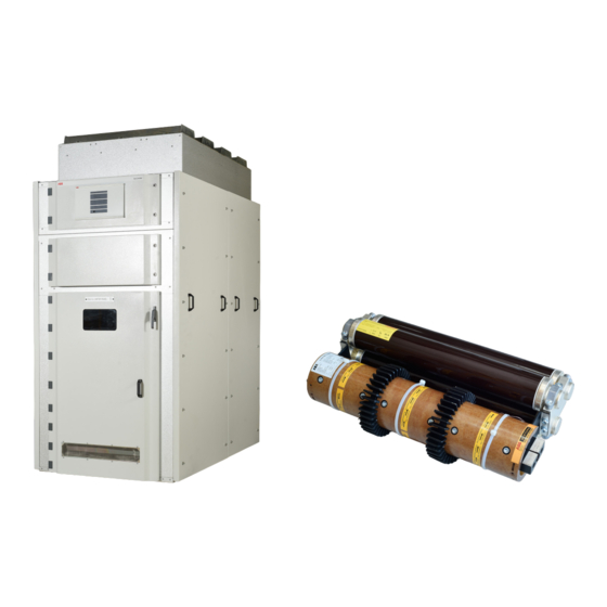
- Page 1 — D I S T R I B U T I O N S O LU T I O N S 36kV I -limiter panel Installation, operation and maintenance manual...
- Page 2 — ABB’s 36kV I -limiter panel is a three-phase, metal enclosed, air-insulated switchgear and all units are factory-assembled, type tested and suitable for indoor applications up to 36 kV. The panels are fitted with -limiter switch inserts as fixed installation along with CTs &...
- Page 3 — Your safety first - always! That's why our instruction manual begins with these recommendations. • Keep this installation, operation and maintenance manual accessible to all personnel involved in installation, operation and maintenance • Ensure that the switchgear and accessories are stored in a closed room free of dust and moisture till erection •...
-
Page 4: Table Of Contents
3 6 K V I L I M I T E R PA N E L I N S TA L L AT I O N , O P E R AT I O N A N D M A I N T E N A N C E M A N U A L —... -
Page 5: General
Any increased ambient temperatures must be taken into operation of these systems. The order related details account in the design of the busbars or their current provided by ABB are also to be taken into account. carrying capacity will be limited Notes on special climatic operating conditions:... -
Page 6: Technical Data
3 6 K V I L I M I T E R PA N E L I N S TA L L AT I O N , O P E R AT I O N A N D M A I N T E N A N C E M A N U A L —... -
Page 7: Tripping Device And Auxiliary Circuits
2.2 I -limiter switch Electrical data Weight Rated power frequency Rated lightning impulse Rated voltage Rated current withstand voltage withstand voltage -limiter insert holder -limiter insert 1250,2000,2500 With cooling fan installed in panel 2.3 Tripping device and auxiliary circuits Electrical data Power consumption Rated supply voltages Device... -
Page 8: Panel Structure And Components
3 6 K V I L I M I T E R PA N E L I N S TA L L AT I O N , O P E R AT I O N A N D M A I N T E N A N C E M A N U A L —... -
Page 9: Interlocks/Protection Against Maloperation
The copper contacts for incoming cable • connections between tripping current connections are connected to bottom of the transformers and clamps -limiter assembly which are supported by • connections between pulse transformers and insulator support. At the out-going side of the clamps -limiter assembly, the jumpers are connected... -
Page 10: Functions Of The I
I -limiter is thus limited. 3.5.2 I -limiter insert Please consult the detailed special publications or the ABB I -limiter brochure for the technical (Figure 3.7) processes involved in short-circuit limiting and The I -limiter insert is the switching element. -
Page 11: Limiter Tm
3.5.3 Tripping current transformers 3.5.4 Tripping device (Figure 3.5) (Figure 3.1) The tripping transformers 9 are current The tripping device is installed in the separate transformers which are installed in series with low voltage compartment above the I -limiter the I -limiter and serve to measure the current compartment. - Page 12 Jaw type fixed contact — Fig 3.2 - Insert holder mounting Contacts for cable connection Support insulators Steel channel Locking handle Fuse assembly Is-limiter insert — Fig 3.3 – Insert mounting T contact limiter top side Hardware Jumpers Earthing bolt Insulator support —...
- Page 13 -limiter insert Contacts for incoming cable connection Phase barrier front LV compartment Support insulators Absorber assembly Explosion vents Shrouds Current transformer 10 Contacts for O/G cable connection 11 Rear phase barrier 12 Rear cover 13 I -limiter insert holder 14 Phase barrier supports 15 Earthing bolt 16 Earthing bar 17 Cooling fan...
- Page 14 L I M I T E R PA N E L I N S TA L L AT I O N , O P E R AT I O N A N D M A I N T E N A N C E M A N U A L Bursting bridge -limiter insert assembly Charge 4.1 Top pole head 4.2 Bottom pole head 5.1 Top insulator 5.2 Bottom insulator Main conductor Tripping contact Mounting hardware Mounting bracket 10 Insulating tube 11 Fuse — Fig 3.7 - Is-limiter assembly...
- Page 15 — Fig 4.1 - Handling with forklit — Fig 4.2 - Handling with forklit...
- Page 16 3 6 K V I L I M I T E R PA N E L I N S TA L L AT I O N , O P E R AT I O N A N D M A I N T E N A N C E M A N U A L Lifting hook Side sheet...
- Page 17 Cable lug Hardware Insulator support Cable gland -limiter assembly Cable connection piece Single core power cable — Fig 5.1 - Incoming cable connection Cable lug Hardware Insulator support Cable gland Cable connection piece Single core power cable — Fig 5.2 - Outgoing cable connection...
- Page 18 3 6 K V I L I M I T E R PA N E L I N S TA L L AT I O N , O P E R AT I O N A N D M A I N T E N A N C E M A N U A L Bracket for switch Explosion vent Aux.
-
Page 19: Dispatch And Storage
— 4. Dispatch and storage 4.1 Condition on delivery 4.3 Transport The factory assembled panels are dispatched Figure 4.1-4.4 without I -limiter inserts (Inserts are packed Normally, each individual panel is a separate separately in separate special packing). transport unit. The panels are fixed on wooden pallet with bolts. -
Page 20: Delivery
3 6 K V I L I M I T E R PA N E L I N S TA L L AT I O N , O P E R AT I O N A N D M A I N T E N A N C E M A N U A L 4.4 Delivery 4.6 Intermediate storage The responsibilities of the consignee when the... -
Page 21: Erection Of The Switchgear On Site
— 5. Erection of the switchgear on site In the interests of the best possible erection sequence, and to ensure a high- quality standard, local installation of the switchgear should only be carried out by specially trained skilled personnel, or at least responsibly managed and supervised. -
Page 22: Fixing I
3 6 K V I L I M I T E R PA N E L I N S TA L L AT I O N , O P E R AT I O N A N D M A I N T E N A N C E M A N U A L It is recommended that the threads or head contact surfaces CAUTION of the screws be lightly oiled or greased, to achieve a... -
Page 23: Earthing The Switchgear
5.6 Earthing the switchgear • Individual parts of the floor covering must be mounted • Cable gland must be moved down so that nuts in the rings fit into corresponding recesses in floor coverings. (Figure 5.4) In this way, the cable passages are sealed •... -
Page 24: Commissioning/Operation
3 6 K V I L I M I T E R PA N E L I N S TA L L AT I O N , O P E R AT I O N A N D M A I N T E N A N C E M A N U A L —... -
Page 25: Start-Up
Any closing lock-outs with the circuit-breakers or switched off. switch disconnectors in series are enabled. CAUTION! Never re-use tripped I -limiter inserts (green indication), irrespective of the condition of the fuse. Repair and testing of -limiter inserts may only be carried out at ABB (manufacturer's works)! -
Page 26: Electrical Displays And Monitoring
3 6 K V I L I M I T E R PA N E L I N S TA L L AT I O N , O P E R AT I O N A N D M A I N T E N A N C E M A N U A L 6.4 Electrical displays and •... -
Page 27: Testing For In-Phase Condition
6.6.2 Testing for in-phase condition 6.6.3 Tests on the pulse transformer Testing of the in-phase condition, e.g. when there No continuity tests may be performed on the is more than one incoming feeder, can be carried higher voltage side winding (secondary winding) out with a suitable phase comparator coupled to of the pulse transformer, as otherwise this might the measuring sockets of the capacitive voltage... -
Page 28: Maintenance
Traces of leakage current on the insulating material It is recommended that ABB service personnel be called in to parts perform servicing and repair work, and this is necessary for Surfaces of the contacts some of the work detailed below. -
Page 29: Servicing
Load-dependent functional test on the current- surface concerned is often effective as a temporary dependent transformer: remedy. It is advisable to request advice from the ABB 1. The current-dependent relay must be activated at a after-sales service department on permanent solutions... -
Page 30: Repair
ABB Calor Emag (manufacturer’s works)! wire brush or Scotch-Brite, and clean with a dry cloth. Then evenly grease the parts (with Isoflex Topas NB 52) -
Page 31: Tests On Interlocks
For the procurement of further spare parts, please contact • It must not be possible to close the circuit-breaker ABB India Ltd. Or on numbers mentioned on service card with the main door of the panel is in open position on panel. -
Page 32: Disposal
ISO 9001 and by the EMS according to ISO 14001. Epoxy resin Separation of metal End of life of product. material and the The ABB company is committed to complying disposal of rest with the relevant legal and other requirements Rubber Disposal for environment protection according to the ISO 140001 standard. - Page 34 We reserve the right to make technical changes or modify the contents of this document without prior notice. With regard to purchase orders, the agreed particulars shall prevail. ABB does not accept any responsibility whatsoever for potential errors or possible lack of information in this document.