
Related Manuals for ABB IRC5P


Summary of Contents for ABB IRC5P
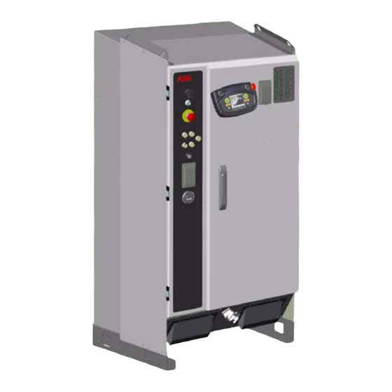
- Page 1 Robotics Product Manual Control Cabinet, IRC5P 3HNA009834-001 en Rev.06...
- Page 3 Product Manual Control Cabinet, IRC5P 3HNA009834-001 en Rev.06 First Edition: 10 Dec. 2007 Last Revised: 08 October 2010 Product Manual, Control Cabinet IRC5P...
- Page 4 Except as may be expressly stated anywhere in this document, nothing herein shall be construed as any kind of guarantee or warranty by ABB for losses, damages to persons or property, fitness for a specific purpose or the like.
-
Page 5: Table Of Contents
Product Manual, Control Cabinet IRC5P Table of Contents Table of Contents Product Manual, Control Cabinet IRC5P 1 Introduction 2 Safety 3 System Description 3.1 Introduction .............. - Page 6 Table of Contents Product Manual, Control Cabinet IRC5P 5.6.4 Connection Overview ............
- Page 7 Product Manual, Control Cabinet IRC5P Table of Contents 8.2.5 Upgrading, Downgrading and Compatibilities ........
- Page 8 Table of Contents Product Manual, Control Cabinet IRC5P 3HNA009834-001 en Rev.06 Product Manual, Control Cabinet IRC5P...
- Page 9 Product Manual, Control Cabinet IRC5P This manual provides information on the installation of the IRC5P control cabinet and associated systems, and instructions for performing preventive maintenance and repair. Before performing any work described in this manual, the Safety WARNING! Manual must be read and understood. Work must only be performed by skilled personnel with the proper training.
- Page 10 3HNA009834-001 en Rev.06 Product Manual, Control Cabinet IRC5P...
-
Page 11: Introduction
Information about maintenance work, including maintenance schedules. Repair Information about replacing components in the controller. Trouble Shooting Description of LED indicators on controller front and general trouble shooting information. Decommissioning General information for decommissioning the controller Product Manual, Control Cabinet IRC5P 3HNA009834-001 en Rev.06... - Page 12 Unit Description, Paint Includes technical description of the units used in the paint 3HNA012856-001 system. Operator’s Manual, IRC5P Includes instructions for setting up conveyor tracking, 3HNA008861-001 entering calibration data etc. 3HNA009834-001 en Rev.06 Product Manual, Control Cabinet IRC5P...
-
Page 13: Safety
• Always be aware of hazards associated with electric power when working with the robot. • Always be aware of hazards related to the applicator. These can be dangers related to the electrostatic high voltage or the bell cup on the bell atomizer. Product Manual, Control Cabinet IRC5P 3HNA009834-001 en Rev.06... - Page 14 2 Safety 3HNA009834-001 en Rev.06 Product Manual, Control Cabinet IRC5P...
-
Page 15: System Description
Repair chapter in this manual. For detailed description of the function of the different control systems in the References control cabinet and purge unit, see ‘Unit Description, IRC5P’. For detailed description of the operation of the pendant, see ‘Operator’s Manual, IRC5P’. -
Page 16: Basic Design
The robot may be supplied without control panel on the control cabinet. The reason for this may be that the control panel is to be installed in an external control desk, or that the robot is controlled from an external PLC via serial lines. 3HNA009834-001 en Rev.06 Product Manual, Control Cabinet IRC5P... - Page 17 Only memory sticks recommended by ABB must be used. Using other CAUTION! memory sticks than recommended may cause RobotWare system failure. For more information on the service connections, see ‘Operator’s Manual, IRC5P’, Installation and Commissioning / Connections. The pendant (Paint Teach Pendant Unit, PTPU, or TPU) is used to perform Pendant robot-near tasks, like jogging.
-
Page 18: Internal Components
M I B- 0 1 MIB- 01 X 1 0 X 10 X1 2 X 1 2 X 13 X 1 3 X 1 1 X 11 SCB-01 Right side wall Drive system 04 3HNA009834-001 en Rev.06 Product Manual, Control Cabinet IRC5P... - Page 19 The computer system for the robot consists of the main computer, mounted on the Computer Systems front door, and the axis computer installed on the cabinet back wall. Product Manual, Control Cabinet IRC5P 3HNA009834-001 en Rev.06...
- Page 20 The light is switched on/off by the door switch. The door switch switches ‘on’ the optional internal light and switches ‘off’ the Door Switch optional cooler when the front door is opened. 3HNA009834-001 en Rev.06 Product Manual, Control Cabinet IRC5P...
-
Page 21: Cabinet Labelling
A connector or terminal board located on one of the units in the cabinet is labelled with the name of the unit in addition to the name of the connector (or terminal board), e.g. MIB-X22 which means connector X22 on the MIB unit. Product Manual, Control Cabinet IRC5P 3HNA009834-001 en Rev.06... -
Page 22: Purge System
The compressed air is kept at a higher pressure than the atmospheric pressure and so preventing hazardous gases from entering the manipulator interior. For more details on the purge unit, see ‘Unit Description, IRC5P’, Purge System. Figure 5 Purge unit design Identification label... -
Page 23: Identification Labels
Purge Supply pressure :.... Min.3.0 max.5.0 bar Maintenance Supply pressure :. Min.0.5 max.1.0 bar Leaquage Compensation :..5 -20 Nl/min. Maintenance pressure :..... Min. 0.8 mbar Enclosure Pressure :....Max. 500 mbar Product Manual, Control Cabinet IRC5P 3HNA009834-001 en Rev.06... - Page 24 3.76 14.8V 0.110 3.76 Intrinsically Safe Outputs for Cl.1, Div.1,Gr. C & D in accordance with Drawing 3HNA012823-001 ABB AS, Robotics Box 265, N-4349 Bryne, NORWAY TYPE ITEM No. 3HNA006149-001 SERIAL No. 3HNA009834-001 en Rev.06 Product Manual, Control Cabinet IRC5P...
- Page 25 FM Class I,II Div.1, Group C,D,G Ref. Dwg. No.: 3HNA010016-001 Un=24VDC, In.sys=0.3A Um=250V, Uo=10.6V, Io=62mA, Po=164mW Group IIB, Ca/Co=16.2uF,La/Lo=35mH Warning: Substitution of components may impair intrinsic safety. Must only be used with ABB Robots. Product Manual, Control Cabinet IRC5P 3HNA009834-001 en Rev.06...
- Page 26 Class I,II Div.1, Group C,D,G Ref. Dwg. No.: 3HNA015815-001 Um=250V, Un=24VDC, Vo=12.3V, Io=13.7mA, Po=42mW Group IIB, Ca/Co=16.2uF, La/Lo=600mH Warning: Substitution of components may impair intrinsic safety. Must only be used with ABB Robots. 3HNA009834-001 en Rev.06 Product Manual, Control Cabinet IRC5P...
-
Page 27: Control Panel Description
Toggle key switch means that the switch returns to off position when released, as indicated by the (“I”) notation. The switch is only applicable if the robot is fitted with HV controller. Product Manual, Control Cabinet IRC5P 3HNA009834-001 en Rev.06... - Page 28 When leaving Manual Reduced Speed mode, an Acknowledge input is required. If operated from the pendant, a dialog for this purpose is shown. For systems controlled by a PLC or RobView, there is a Paint Command available for this purpose. 3HNA009834-001 en Rev.06 Product Manual, Control Cabinet IRC5P...
-
Page 29: Pendant Description
If the pendant is not connected, a dummy connector must be installed in Important: its place to avoid breaking the emergency stop chain. The pendant and connection are explosion protected Exi for operation in hazardous areas. Product Manual, Control Cabinet IRC5P 3HNA009834-001 en Rev.06... - Page 30 3 System Description 3.4 Pendant Description 3HNA009834-001 en Rev.06 Product Manual, Control Cabinet IRC5P...
-
Page 31: Technical Specifications
4 Technical Specifications 4.1 Introduction 4 Technical Specifications 4.1 Introduction This chapter provides technical specifications on the IRC5P Controller, Pendant and About this Chapter Purge Unit. Repair work on the controller must only be performed in accordance WARNING! with procedures given in the Repairs chapter in this manual. -
Page 32: Controller Specifications
100 Mbit/s (<10m): CAT5E, 100 Base T STP 100 Mbit/s (10-100m): CAT6, 100 Base T STP ACA Console port: RS232 (Baud rate 9600 Bd, flow control Xon/Xoff) USB connector: USB memory stick (to be ordered from ABB) 3HNA009834-001 en Rev.06 Product Manual, Control Cabinet IRC5P... - Page 33 Different types of distributed I/O units can be installed. The following table shows Inputs and Outputs the maximum number of physical signals that can be used on each unit. For more details, see technical specifications for relevant unit in ‘Unit Description, IRC5P’, Distributed I/O. Type...
- Page 34 Controller dimensions are shown in the illustration below. Dimensions Figure 14 Controller dimensions Min.100 Min.100 122.5 157.5 Top view Bottom view 4 x Ø14 (foot print) 1450 Front view Side view All dimensions in mm 3HNA009834-001 en Rev.06 Product Manual, Control Cabinet IRC5P...
-
Page 35: Pendant Specifications
Buttons for menu navigation. Orange key group Buttons for manipulator motion. Blue key group Buttons for information on the current operation. Soft keys Buttons with functions that are indicated on the display. Cable 10m standard Product Manual, Control Cabinet IRC5P 3HNA009834-001 en Rev.06... -
Page 36: Purge Unit Specifications
Air Pressure and Consumption Min. supply pressure: 3 bar Air consumption during purging min. 500 NL/min. Air consumption during maintenance 10-20 NL/min. Air pressure purging: 3 bar Air pressure maintenance: 0.5 - 1 bar 3HNA009834-001 en Rev.06 Product Manual, Control Cabinet IRC5P... - Page 37 Air out connection for purge connection(s) PURGE VALVE ASSEMBLY Supply air connection Ground clamp Purge control valve, YV1 58.5 Ø 73 G 1/4" Ø 4.1 46.7 All dimensions in mm Purge connection Product Manual, Control Cabinet IRC5P 3HNA009834-001 en Rev.06...
- Page 38 4 Technical Specifications 4.4 Purge Unit Specifications 3HNA009834-001 en Rev.06 Product Manual, Control Cabinet IRC5P...
-
Page 39: Installation And Commissioning
For complete installation instructions, see also ‘Product Manual, Manipulator’ for installation of the manipulator, ‘Unit Description, Paint’ for connection of the paint system and ‘Operator’s Manual, IRC5P’ for starting up the robot system. Before any work described in this chapter is commenced, it is extremely important Safety Information that all safety information is observed. - Page 40 ‘Arrival Quality Report’, found in the ‘Documents on Delivery’ folder. Also check that all components are correctly delivered in accordance with the packing list attached to the shipping crate. 3HNA009834-001 en Rev.06 Product Manual, Control Cabinet IRC5P...
-
Page 41: Installation Guidelines
5 Installation and Commissioning 5.1 Introduction 5.1.2 Installation Guidelines The following sections detail the main steps on how to unload, transport, install and General connect the IRC5P controller and purge unit. Installation Procedure Action Reference Prepare for installation. What you should be aware of before starting to install the controller is described in section ’Introduction’... -
Page 42: Controller Connections Overview
M I B - 0 1 MIB-01 X 1 7 X 1 7 X 1 8 X 1 8 X 1 8 X1 0 X1 3 X1 1 SCB-01 Right side wall Drive system 04 3HNA009834-001 en Rev.06 Product Manual, Control Cabinet IRC5P... - Page 43 ’24 VDC for External Use’ on page 120 Optional field bus nodes ‘Unit Description, IRC5P’ XT65 CAN1.2 for external distributed I/O ‘Unit Description, IRC5P’, Distributed I/O XT10 CAN1.1 for internal distributed I/O ‘Unit Description, IRC5P’, Distributed I/O Optional home position relay ’Home Position Switch’...
-
Page 44: Safety Connection Board
SCB - X12 System connector Panel connection to SIB - X10 SCB - X13 Emergency stop reset ’Robot Safety System Connections’ on page 64 High voltage interlock ’Cabin Safety System Connections’ on page 78 3HNA009834-001 en Rev.06 Product Manual, Control Cabinet IRC5P... -
Page 45: External Connection Overview
Different field bus nodes are available for connection of digital and analog I/O, field Distributed I/O bus nodes for communication with PLC etc. For information on connections etc, see ‘Unit Description, IRC5P’, Distributed I/O. Ethernet can be used to connect a PC to the controller for download of robot Ethernet Communication programs, configurations, backup etc. -
Page 46: Component Installation
About this Section unit, and information for performing necessary system interconnections. Following sections are available: • Installing the control cabinet • Installing the purge unit • Perform system component interconnections • IS Ground connection 3HNA009834-001 en Rev.06 Product Manual, Control Cabinet IRC5P... -
Page 47: Lifting And Transporting The Controller
If lifting straps are used, they must be attached to all 4 lifting eyes. CAUTION! For information on location of the cabinet and information on how to secure the cabinet to the floor, etc., see ’Cabinet Location’ on page 48. Product Manual, Control Cabinet IRC5P 3HNA009834-001 en Rev.06... -
Page 48: Cabinet Location
If the plant has a history of extreme mains power transients and interference Isolation Transformer voltages, an isolation transformer or an interference suppression device should be installed. 3HNA009834-001 en Rev.06 Product Manual, Control Cabinet IRC5P... -
Page 49: Purge Unit Installation
‘Product Manual, Manipulator’, System Description. For specification of the purge air, see also ’Purge Unit Specifications’ on page 36. Product Manual, Control Cabinet IRC5P 3HNA009834-001 en Rev.06... - Page 50 This is also marked on the hose. The hose must not be joined in a manner which will restrict the air supply. 3HNA009834-001 en Rev.06 Product Manual, Control Cabinet IRC5P...
-
Page 51: System Interconnections
The electrical interconnections are depending on manipulator type. Connections for the different manipulator types are described as follows: – ’Electrical Interconnections IRB 5500’ on page 52 – ’Electrical Interconnections IRB 52, IRB 5400, IRB 580, IRB 540’ on page 55 Product Manual, Control Cabinet IRC5P 3HNA009834-001 en Rev.06... -
Page 52: Electrical Interconnections Irb 5500
Connect robot purge valve cable to connector MIB-X6. Connect robot motor 1-6 driver cable directly to motor drivers, connector X11 - X16. Connect robot DC power cable to connector PDB-X20. Connect communication robot cable to connector MIB-X4. 3HNA009834-001 en Rev.06 Product Manual, Control Cabinet IRC5P... - Page 53 11. Fasten all screens to the cable inlet bracket. All cables must be secured with strain relief clamps at the bottom CAUTION! entrance and p-clips at connection point. - Ref: ’Clamping Cables’ on page 213. Product Manual, Control Cabinet IRC5P 3HNA009834-001 en Rev.06...
- Page 54 *1 For non-ex process cabinet, the purge connection is integrated in the process cabinet. *2 Process cabinet is only applicable for IRB 5500 Slim Arm. *3 Purge connection is integrated in the CBS robot. 3HNA009834-001 en Rev.06 Product Manual, Control Cabinet IRC5P...
-
Page 55: Electrical Interconnections Irb 52, Irb 5400, Irb 580, Irb 540
Pump cabinet Connector bracket on *1 Connection for pumps in robot cabinet left side wall *2 Connection for pumps in pump cabinet Connect purge valve cable to connector AX1-YV1 on purge unit. Product Manual, Control Cabinet IRC5P 3HNA009834-001 en Rev.06... - Page 56 12. Fasten all screens to the cable inlet bracket. All cables must be secured with strain relief clamps at the bottom CAUTION! entrance and p-clips at connection point. - Ref: ’Clamping Cables’ on page 213. 3HNA009834-001 en Rev.06 Product Manual, Control Cabinet IRC5P...
- Page 57 Paint Robot Intrinsically safe signals Communication robot + CBS Flexible hose Robot power CBS Robot Purge connection is integrated in the CBS robot CBS power X211 Connector bracket on cabinet left side wall Product Manual, Control Cabinet IRC5P 3HNA009834-001 en Rev.06...
- Page 58 Purge air hose Purge unit Purge connection is integrated valve assembly in the CBS robot X211 Connector bracket on Intrinsically safe signals cabinet left side wall CBS Communication CBS power CBS Robot 3HNA009834-001 en Rev.06 Product Manual, Control Cabinet IRC5P...
-
Page 59: Is-Ground Connection
Connect an IS-ground wire of minimum 10mm² (AWG 6) between IS-ground screws as follows: – Manipulator - purge unit - controller. – Or alternatively, manipulator - controller and purge unit - controller. Product Manual, Control Cabinet IRC5P 3HNA009834-001 en Rev.06... - Page 60 If required, an additional ground wire can be installed as shown in Figure The PE-ground rail in the control cabinet is connected to the factory PE-ground by means of the ground wire in the mains supply cable. 3HNA009834-001 en Rev.06 Product Manual, Control Cabinet IRC5P...
-
Page 61: Connectors
Paint pumps in manipulator / pump Optional connector cabinet or 8th axis connector X211 CBS robot Optional connector Identification of the signals in the above connectors can be found on the following pages. Product Manual, Control Cabinet IRC5P 3HNA009834-001 en Rev.06... - Page 62 0V Brake release emy. ext. 0V Power MCOB +24V Power function 0V Power function Manipulator enable +24V High voltage controller supply 0V High voltage controller supply SMU +24V SYS SMU 0V SYS 3HNA009834-001 en Rev.06 Product Manual, Control Cabinet IRC5P...
- Page 63 M3 U DCU PUMP MOTOR RUN CHAIN 1 OUT M3 V DCU PUMP MOTOR RUN CHAIN 2 OUT M3 W DCU PUMP MOTOR RUN CHAIN 1 IN RUN CHAIN 2 IN 24V POWER POWER BRAKE Product Manual, Control Cabinet IRC5P 3HNA009834-001 en Rev.06...
-
Page 64: Robot Safety System Connections
Before any connections are made in the safety chains, section ’Safety System Standards’ on page 65 must be read. All screw connections in the safety system must be tightened in accordance with Tightening Torque ’Tightening Torques’ on page 216. 3HNA009834-001 en Rev.06 Product Manual, Control Cabinet IRC5P... -
Page 65: Safety System Standards
Emergency Stop Category 1 is a controlled stop function which will allow the robot Emergency Stop Category 1 control system to stop the motion of the robot while the robot is running in the Product Manual, Control Cabinet IRC5P 3HNA009834-001 en Rev.06... - Page 66 The dual safety chains are monitored by software and hardware. If one of the chains Chain Monitoring does not activate within a time T after the other chain is activated, an error will occur. In this system, the time T is equal to 2 seconds. 3HNA009834-001 en Rev.06 Product Manual, Control Cabinet IRC5P...
-
Page 67: Safety System Connection Overview
’Emergency Stop Chain Supply’ on page 70. If required, install Emergency Stop Switch(es) (Category 0) in addition to the Emergency Stop Switches on the main panel and pendant. For information, see Product Manual, Control Cabinet IRC5P 3HNA009834-001 en Rev.06... - Page 68 If required, install Cabin Safety Switches. These functions can be used to disable functions such as fluid pumps, spray-gun, bell, electrostatic high voltage etc. for safety reasons. For information on these connections, see section ’Cabin Safety System Connections’ on page 78. 3HNA009834-001 en Rev.06 Product Manual, Control Cabinet IRC5P...
- Page 69 (switch closed) without breaking this connection (switch opened). When the test period is completed, all jumpers must be removed and switches installed in their place. Product Manual, Control Cabinet IRC5P 3HNA009834-001 en Rev.06...
-
Page 70: Emergency Stop Chain
On button on the control panel, but the signal may also be applied from an external PLC or reset switch. The emergency stop reset signal is also used to send an acknowledge signal to various internal and external systems. 3HNA009834-001 en Rev.06 Product Manual, Control Cabinet IRC5P... - Page 71 Figure 31. Supply voltage should be 24VDC, max 500mA. The external chain connection must be non-capacitive. To avoid damage to the internal emergency stop chain in the IRC5P WARNING! controller and thereby violate the safety system, the customer must provide individual monitoring of safety chain 1 and 2 and current limiting at 500mA in the external chain.
- Page 72 EXT EMY STOP RESET SCB-X13:1 +24VDC SCB-X13:2 Internal reset KA12 KA6&13 Emy stop relays KA11 KA15 KA15 KA1&9, KA11, KA28 KA29 SCB-X2:9 SCB-X2:10 SCB-X2:11 SCB-X2:12 = Chain monitoring points EMERGENCY STOP FEEDBACK 3HNA009834-001 en Rev.06 Product Manual, Control Cabinet IRC5P...
-
Page 73: Run Chain
’Safety System Standards’ on page 65. To prevent running the robot without paying attention to the auto mode stop Note: switch, the robot is shipped without jumper installed in this position. Product Manual, Control Cabinet IRC5P 3HNA009834-001 en Rev.06... - Page 74 Figure 32. The switch must be of a type which will be closed when activated (spray booth door closed etc.). The switch must comply with ’Safety System Standards’ on page 65. 3HNA009834-001 en Rev.06 Product Manual, Control Cabinet IRC5P...
- Page 75 An attempt to apply power to the robot from the pendant without having activated the hardware motor-on will result in a warning message. Software will always switch off this signal when hardware is not allowing motor-on. Product Manual, Control Cabinet IRC5P 3HNA009834-001 en Rev.06...
- Page 76 EXT_DS2 SCB-X2:6 SCB-X2:8 DELAY DELAY KA19 KA24 GENERAL MODE STOP (Cat.0) SCB-X2:1 SCB-X2:3 +24VDC +24VDC EXT_GMS1 EXT_GMS2 SCB-X2:2 SCB-X2:4 KA20 KA25 Emy stop KA11 KA15 Motor control relays = Chain monitoring points 3HNA009834-001 en Rev.06 Product Manual, Control Cabinet IRC5P...
-
Page 77: Emergency Brake Release Switch
X24 on the PDB board as shown in the figure above. Install switch element inside a box with a breakable glass. Make a sign similar to the one shown in the illustration and place it above or beside the switch. Product Manual, Control Cabinet IRC5P 3HNA009834-001 en Rev.06... -
Page 78: Cabin Safety System Connections
Before any connections are made in the safety chains, section ’Safety System Standards’ on page 65 must be read. All screw connections in the safety system must be tightened in accordance with Tightening Torque ’Tightening Torques’ on page 216. 3HNA009834-001 en Rev.06 Product Manual, Control Cabinet IRC5P... -
Page 79: Cabin Safety Connection Overview
If required, connect Process Interlock switch for switching off all paint related functions. For information, see ’Process Interlock’ on page 83. If required, install Emergency Shut-Down valve in manipulator. For information, see ’Emergency Shut Down Valve’ on page 85. Product Manual, Control Cabinet IRC5P 3HNA009834-001 en Rev.06... -
Page 80: Cabin Interlock
Figure 35. The switch must be of a Normal Open fail safe type, which will be opened to disable paint functions. The switch must comply with ’Safety System Standards’ on page 65. 3HNA009834-001 en Rev.06 Product Manual, Control Cabinet IRC5P... -
Page 81: High Voltage Interlock
35. The switch must be of a Normal Open fail safe type which will be opened to switch off the high voltage. The switch must comply with ’Safety System Standards’ on page 65. Product Manual, Control Cabinet IRC5P 3HNA009834-001 en Rev.06... -
Page 82: System 2 Interlock
35. The switch must be of a Normal Open fail safe type which will be opened to disable system 2 functions. The switch must comply with ’Safety System Standards’ on page 65. 3HNA009834-001 en Rev.06 Product Manual, Control Cabinet IRC5P... -
Page 83: Process Interlock
Figure 35. The switch must be of a Normal Open fail safe type which will be opened to disable process functions. The switch must comply with ’Safety System Standards’ on page 65. Product Manual, Control Cabinet IRC5P 3HNA009834-001 en Rev.06... - Page 84 VCD2… controlled valves +24V_HV High Voltage Controller, HVC SAFETY1_PWR FlexShield, etc. Purge relay Pump motors DCU (CBS) = Chain monitoring points Power Distribution Board, PDB = Contactors are normal closed during operation 3HNA009834-001 en Rev.06 Product Manual, Control Cabinet IRC5P...
-
Page 85: Emergency Shut Down Valve
Install emergency shut down valve. Connect valve to terminal XT2: pin 1(+24VDC) Connections and 2 (GND). Install voltage suppression diode as shown in diagram above. Route main air supply to the robot’s paint systems via the valve. Product Manual, Control Cabinet IRC5P 3HNA009834-001 en Rev.06... -
Page 86: Encoder And Sync Switch Installation
The following sections provide information on the installation and connection of the encoder and sync switch. For information on how to enter the required data and parameters for setting up the tracking function, see ‘Operator’s Manual, IRC5P’. To ensure good operation of the tracking function, following points must be... -
Page 87: Encoder Specifications
Figure 37 Encoder connection - Lenord & Bauer Single phase 2 phase (not used) 0° 90° Encoder connector (Not used) (Mating face of connector on encoder) 1 encoder cycle = 1 count Internal used = 4 counts Product Manual, Control Cabinet IRC5P 3HNA009834-001 en Rev.06... - Page 88 2 phases (0° and 90°) of the output signals, - Ref: Figure For information on how to find encoder rotating direction, see ‘Operator’s Manual, IRC5P’, chapter ‘Installation and Commissioning’. Technical Specifications Output signal: Open collector PNP or NPN output...
-
Page 89: Sync Switch Specifications
(If the switch gives multiple signals when an object passes, the parameter SyncFilter can be set so that only one signal is accepted. For information, see ‘Operator’s Manual, IRC5P’). Different types of switching devices may be used. Most common is a limit switch, Switch Types but photocell with switch output or Namur initiator etc. -
Page 90: Connection Overview
Extra encoders can be used for a second conveyor, a backup encoder, or for monitoring of paint flow e.g. when using Küppers initiators. For more information on monitoring paint flow, refer to the gear flow meter in the ‘Unit Description, Paint’ manual. 3HNA009834-001 en Rev.06 Product Manual, Control Cabinet IRC5P... -
Page 91: Encoder Installation
If a ‘Take-Up’ is used (used to keep tension in the conveyor chain), the encoder Conveyors with ‘Take-Up’ Station must be placed on the same side of the ‘Take-Up’ station as the robot. Product Manual, Control Cabinet IRC5P 3HNA009834-001 en Rev.06... - Page 92 The 2 LEDs for each of the encoders on the cabinet LED display will flash to show the pulses from the encoder. By running the conveyor extremely slowly, these indicators can be used to verify the pulses from the encoder. 3HNA009834-001 en Rev.06 Product Manual, Control Cabinet IRC5P...
- Page 93 ‘on’ to be fed to a robot which is ‘off’. If an external supply is used, the internal supply must not be connected. Product Manual, Control Cabinet IRC5P 3HNA009834-001 en Rev.06...
-
Page 94: Sync. Switch Installation
(or suspension) will slide on the switch arm, causing inaccurate switching. Figure 43 Sync switch mounting Correct Correct Not correct Not correct 3HNA009834-001 en Rev.06 Product Manual, Control Cabinet IRC5P... - Page 95 Alternative B (PNP) or Alternative C (NPN). An ex sync switch must be connected via a transformer isolated barrier to avoid Ex Connection violating the explosion safety for the spray booth. Product Manual, Control Cabinet IRC5P 3HNA009834-001 en Rev.06...
- Page 96 An ex type initiator may be used as alternative to a switch. Such a switch device in conjunction with a transformer isolated barrier can be installed as shown in Alternative B. 3HNA009834-001 en Rev.06 Product Manual, Control Cabinet IRC5P...
-
Page 97: Misc. System Connections
’Pendant Connection’ on page 103 • ’Cabinet Cooler Installation’ on page 105 • ’Servo Disconnect’ on page 109 • ’Home Position Switch’ on page 110 • ’Purge Unit w/Connector Box’ on page 111 Product Manual, Control Cabinet IRC5P 3HNA009834-001 en Rev.06... -
Page 98: Digital I/O Connection
208 and ’Bonding Information’ on page 211. For information on how to setup the digital inputs and outputs in the control system, see ‘Operator’s Manual, IRC5P, chapter ‘Installation and Commissioning’. 3HNA009834-001 en Rev.06 Product Manual, Control Cabinet IRC5P... -
Page 99: Remote Panel Connections
Connection Board, SCB. The robot can not be operated without cabinet control panel or remote panel / Note: PLC installed. The following illustration shows the connections for remote panel. Remote Panel Connections Product Manual, Control Cabinet IRC5P 3HNA009834-001 en Rev.06... - Page 100 For more details on the function of the switches, see ’Control Panel Description’ References page 27. For control cabinet internal wiring information on the remote panel functions, see circuit diagrams supplied with the robot. 3HNA009834-001 en Rev.06 Product Manual, Control Cabinet IRC5P...
-
Page 101: Ethernet Communication
5 Installation and Commissioning 5.7 Misc. System Connections 5.7.4 Ethernet Communication Ethernet communication is a standard function in the IRC5P control cabinet and General may be used for communication between the robot control cabinet and an external PC etc., or for including one or more robots in an Ethernet network. - Page 102 Ethernet TPE Connector Ethernet TPE Connector Connector Signal name Description Transmit data line + Transmit data line - Receive data line + Not connected Not connected Receive data line - Not connected Not connected 3HNA009834-001 en Rev.06 Product Manual, Control Cabinet IRC5P...
-
Page 103: Pendant Connection
The hot plug connection is an optional connector located on the side of the cabinet, Hot Plug Connection to enable connecting and disconnecting the pendant during operation of the cabinet without breaking the emergency stop chain. Figure 51 Pendant hot plug connection Hot Plug Connector Product Manual, Control Cabinet IRC5P 3HNA009834-001 en Rev.06... - Page 104 Check that connector is connected to PE-ground as described in ’IS-Ground Connection’ on page 59. For information on the hot plug function, see ‘Operator’s Manual, IRC5P’, Installation and Commissioning / Connections / Connecting the Paint Teach Pendant Unit. 3HNA009834-001 en Rev.06...
-
Page 105: Cabinet Cooler Installation
Cabinet side wall Drain water Drain hose container connection All dimensions in mm Mains overload Cooler protection, FR1 Optional internal light Door switch XT1.1 Normal Closed when door open Factory 115/230 VAC supply Product Manual, Control Cabinet IRC5P 3HNA009834-001 en Rev.06... - Page 106 – Ensure that the door switch is open when the control cabinet door is open. To minimize condensation inside the control cabinet, cooling is switched off when control cabinet door is open. 3HNA009834-001 en Rev.06 Product Manual, Control Cabinet IRC5P...
- Page 107 Check that the dissipated heat loss does not cooling circuit. exceed the useful cooling output of the cooler. After rectifying the fault, you need to reset the cooler controller manually, ref ’Resetting Cooler Controller’ on page 108. Product Manual, Control Cabinet IRC5P 3HNA009834-001 en Rev.06...
- Page 108 ’Temperature Adjustment’ on page 107. Press reset button for at least 3 seconds. The red LED is extinguished. Reinstall the cooler controller trim panel, as described in ’Temperature Adjustment’ on page 107. 3HNA009834-001 en Rev.06 Product Manual, Control Cabinet IRC5P...
-
Page 109: Servo Disconnect
1 MIB- X11 Optional servo disconnect The terminal XT5 is located at the bottom of the controller, see Figure Max. cable length from control cabinet to external switch is 25 meter. Product Manual, Control Cabinet IRC5P 3HNA009834-001 en Rev.06... -
Page 110: Home Position Switch
1. A relay is located in the control cabinet. The principle diagram is shown in following illustration. Figure 56 Home position switch, principle diagram Control cabinet Manipulator Relay +24VDC The relay with terminal X1 is located at the bottom of the controller, see Figure 3HNA009834-001 en Rev.06 Product Manual, Control Cabinet IRC5P... -
Page 111: Purge Unit W/Connector Box
Purging pressure gauge Maintenance pressure regulator Maintenance pressure gauge Purge sensor connector Purge valve connector (located behind purge sensor connector) Cables from control cabinet Flexible hose to robot All dimensions in MM Product Manual, Control Cabinet IRC5P 3HNA009834-001 en Rev.06... - Page 112 The flexible hose must not be bent to a radius smaller than 250 mm. Note: Remove cover for purge unit connection box. Retain cover, screws and gasket for later re-installation. 3HNA009834-001 en Rev.06 Product Manual, Control Cabinet IRC5P...
- Page 113 10. Make sure that the gasket for the purge unit cover is properly positioned, install cover and tighten attachment screws. Make sure that all screws are in place to prevent air leakage. Product Manual, Control Cabinet IRC5P 3HNA009834-001 en Rev.06...
-
Page 114: Power Connections
• ’Transformer Wiring’ on page 117 • ’Supply for Internal Light’ on page 118 • ’Internal Supply for Service Outlet’ on page 119 • ’24 VDC for External Use’ on page 120 3HNA009834-001 en Rev.06 Product Manual, Control Cabinet IRC5P... -
Page 115: Mains Power Connection
Make sure that mains fuses are removed before continuing. WARNING! Route mains power cable as shown in Figure 59. Dismantle cable and install cable clamp. For location of power connection, see ’Controller Connections Overview’ on page 42 Product Manual, Control Cabinet IRC5P 3HNA009834-001 en Rev.06... - Page 116 Due to the autotransformer / drive system / mains filter configuration in Important: the IRC5P controller, an imbalance between the supply phases to the system can occur during operation of the robot, and especially when switching the system ‘on’ and when applying power to the robots drive system (Motor On). This may cause the earth fault protection to trip if a protection with too low release current is used, and especially if more robots share the same earth fault protection.
-
Page 117: Transformer Wiring
If wiring is not correct, move wires for phase 1, 2 and 3 to correct terminal. For information on tightening torque for terminal connections, see ’Tightening Torques’ on page 216. Check that supply overload protection is set to 16A. Product Manual, Control Cabinet IRC5P 3HNA009834-001 en Rev.06... -
Page 118: Supply For Internal Light
For information on tightening torque for terminal connections, see ’Tightening Torques’ on page 216. For connection for cooler, see ’Cabinet Cooler Installation’ on page 105. 3HNA009834-001 en Rev.06 Product Manual, Control Cabinet IRC5P... -
Page 119: Internal Supply For Service Outlet
FU2/FU3 Fuse FU1 - 230V, 3.15A Fuse FU2 - 115V, 6.3A Supply overload protection, FR2 For information on tightening torque for terminal connections, see ’Tightening Torques’ on page 216. Product Manual, Control Cabinet IRC5P 3HNA009834-001 en Rev.06... -
Page 120: Vdc For External Use
I/O units. The neutral wire in the external supply must be connected in such a way to prevent the maximum permitted potential difference in the chassis earth from being 3HNA009834-001 en Rev.06 Product Manual, Control Cabinet IRC5P... - Page 121 External supply must confirm to following specifications. Potential difference to chassis earth: Max. 60 V continuous Permitted supply voltage: 19 - 35 V including ripple Product Manual, Control Cabinet IRC5P 3HNA009834-001 en Rev.06...
-
Page 122: Concluding Activities
‘Installation Checklist’ supplied with the robot should be filled in. 3HNA009834-001 en Rev.06 Product Manual, Control Cabinet IRC5P... -
Page 123: Preventive Maintenance
• Wipe all surfaces clean before starting maintenance procedures. • To avoid unnecessary contamination by dust etc., always clean outside of control cabinet and manipulator before opening the cabinet door. Product Manual, Control Cabinet IRC5P 3HNA009834-001 en Rev.06... -
Page 124: Maintenance Chart
’Replacement of Servo Fan Unit’ on page 159. ’Check the Cooler’ on page 128, if cooler is fitted. Monthly*1 *1 Interval strongly dependent on environmental conditions. *2 Depending on robot operating hours and temperature. 3HNA009834-001 en Rev.06 Product Manual, Control Cabinet IRC5P... -
Page 125: General Maintenance
/ outlet are kept clean. When cleaning, use a dusting brush and a vacuum cleaner to collect the dust brushed off. Do not clean components directly with the vacuum cleaned as this may cause ESD discharge which may damage components. Product Manual, Control Cabinet IRC5P 3HNA009834-001 en Rev.06... -
Page 126: Clean/Replace Filter
Alternatively, the filter can be blown clean with compressed air from the clean- air side. Slide filter holder with new filter in and down into position. The cabinet can be operated without filter if the environment is clean. 3HNA009834-001 en Rev.06 Product Manual, Control Cabinet IRC5P... -
Page 127: Checking The Measuring System Battery
If the control cabinet controls a CBS unit in addition to the robot, or if the Note: robot is an 8 axis robot, the life time for the battery will be half the time described above (2 e.a. SMU units are used). Product Manual, Control Cabinet IRC5P 3HNA009834-001 en Rev.06... -
Page 128: Check The Cooler
10. Clean the louvered grill, cover, fan, heat exchanger coil (65/5) and compressor chamber, using a vacuum cleaner or compressed air. Any stubborn oil stains may be removed using a nonflammable detergent, such as a degreaser. For more information, see manufacturer’s documentation. 3HNA009834-001 en Rev.06 Product Manual, Control Cabinet IRC5P... -
Page 129: Repair
In such cases, the defective module or component should be replaced on site. The faulty item should be sent to your local ABB organization for service. Make sure that any replacement items are available before performing any repair Replacement Items procedures. - Page 130 For description of the calibration function and procedure for entering calibration data, see ‘Operator’s Manual - IRC5P’. Electronic devices are sensitive to static electricity. If handled incorrectly, the unit ESD Precautions may be permanently damaged.
-
Page 131: Replacement Of Control Panel Board, Cpb
Panel door clamps Button attachment screw Mode selector connector Button locking pin – For information on the CPB board, see ‘Unit Description, IRC5P’ References – Hand tools Tools and Items The procedure describes how to remove the control panel board. - Page 132 Place new panel board in position on panel button bodies and carefully push panel into position. Install panel attachment screws and tighten. Connect panel board connector. Close panel door and controller front door. 3HNA009834-001 en Rev.06 Product Manual, Control Cabinet IRC5P...
-
Page 133: Replacement Of System Led Board, Aled
Figure 68 System LED board, ALED System Led Board, ALED Connectors Attachment screws – For information on the ALED board, see ‘Unit Description, IRC5P’ References – Hand tools Tools and Items The procedure describes how to remove the system LED board. - Page 134 ‘off’ and all safety precautions under ‘Removal’ have been read. Place the board in position over the attachment holes. Make sure the orientation of the board is correct. Install attachment screws and tighten. Insert connectors. Close controller front door. 3HNA009834-001 en Rev.06 Product Manual, Control Cabinet IRC5P...
-
Page 135: Replacement Of Door Fan Unit
Also make sure that possible other connected systems are ‘off’. Open controller front door and locate the fan unit (69/1). Cut cable strap (69/2) securing cable to fan unit. Disconnect connector (69/3). Product Manual, Control Cabinet IRC5P 3HNA009834-001 en Rev.06... - Page 136 Place the fan unit in position over the attachment screws. Slide the unit into position and tighten attachment screws. Insert connector. Secure cable with a new cable strap. Close controller front door. 3HNA009834-001 en Rev.06 Product Manual, Control Cabinet IRC5P...
-
Page 137: Replacement Of Axis Computer, Pdb, Pib, Sib, Mib, Scb
When replacing the PIB board, the key chip must be moved to the new PIB Note: board. For information on the key chip, see ‘Unit Description, IRC5P’, section Paint Control Module / Paint Interface Board, PIB. No repair work must be performed on the robot before the safety... - Page 138 Make sure that the new unit is of the same type as the old unit. For Note: information on the different types used, see ‘Unit Description, IRC5P’. Place new unit in position over the attachment screws. Slide the unit into position and tighten attachment screws.
-
Page 139: Replacement Of Pendant Interface Board, Tib
Upper and lower attachment screws TIB ribbon connector Ex sync signal connection Ground connection – For information on the TIB board, see ‘Unit Description, IRC5P’ References – Hand tools Tools and Items The procedure describes how to remove the TIB board. - Page 140 Place new TIB board assembly in position over the pendant connector inside the cabinet. Carefully press the unit into position on the connector. Install attachment screws and tighten screws. Insert connectors and connect ground wire. Close controller front door. 3HNA009834-001 en Rev.06 Product Manual, Control Cabinet IRC5P...
-
Page 141: Replacement Of I/O Units
Removing I/O unit type 1 I/O unit type 2 spring loaded locking device I/O unit type 2 mounting rail – For information on connections of the I/O unit, see ‘Unit Description, IRC5P’, References Distributed I/O. – For information on configuration of the I/O units, see ‘Operating Manual, RobotStudio’. - Page 142 ‘off’ and all safety precautions under ‘Removal’ have been read. Hook the unit back onto the mounting rail and snap it gently into position. Reconnect all connectors disconnected during removal. Close controller front door. 3HNA009834-001 en Rev.06 Product Manual, Control Cabinet IRC5P...
-
Page 143: Replacement Of Computer Unit
The unit is sensitive to ESD. Before handling the unit, please observe CAUTION! the safety information in ’ESD Precautions’ on page 130. Turn the electrical disconnect switch ‘off’ and lock switch in ‘off’ position. Product Manual, Control Cabinet IRC5P 3HNA009834-001 en Rev.06... - Page 144 Lower the unit into position. Re-install Compact Flash card. For description, see ’Replacement of Compact Flash’ on page 151. Reconnect all connectors to the computer unit. Re-install top cover. Close controller front door. 3HNA009834-001 en Rev.06 Product Manual, Control Cabinet IRC5P...
-
Page 145: Replacement Of Computer Unit Mother Board
Make sure that the mains switch is ‘off’ and locked in ‘off’ position WARNING! before continuing. Also make sure that possible other connected systems are ‘off’. Remove the Computer Unit assembly as described in procedure ’Replacement of Computer Unit’ on page 143. Product Manual, Control Cabinet IRC5P 3HNA009834-001 en Rev.06... - Page 146 Re-install Compact Flash card. For description, see ’Replacement of Compact Flash’ on page 151. Re-install the computer unit as described in procedure ’Replacement of Computer Unit’ on page 143. Close controller front door. 3HNA009834-001 en Rev.06 Product Manual, Control Cabinet IRC5P...
-
Page 147: Replacement Of Pci Boards In Computer Unit Slots
Board attachment screw – ’Replacement of Computer Unit’ on page 143 References – For information on the PCI boards, see ‘Unit Description, IRC5P’ manual – Hand tools Tools and Items The procedure describes how to remove a PCI board. Removal... - Page 148 Refit the computer unit cover by connecting fan unit connector, placing cover in position and installing attachment screws. Refit the computer unit as described in procedure ’Replacement of Computer Unit’ on page 143. Close controller front door. 3HNA009834-001 en Rev.06 Product Manual, Control Cabinet IRC5P...
-
Page 149: Replacement Of Fieldbus Adapter
Also make sure that possible other connected systems are ‘off’. Remove the Computer Unit assembly as described in procedure ’Replacement of Computer Unit’ on page 143. Remove cover attachment screws, disconnect fan unit connector and remove cover. Product Manual, Control Cabinet IRC5P 3HNA009834-001 en Rev.06... - Page 150 Refit the computer unit cover by connecting fan unit connector, placing cover in position and installing attachment screws. Refit the computer unit as described in procedure ’Replacement of Computer Unit’ on page 143. Close controller front door. 3HNA009834-001 en Rev.06 Product Manual, Control Cabinet IRC5P...
-
Page 151: Replacement Of Compact Flash
The Compact Flash card is located on the computer unit mother board as shown Location below. The card is accessible without removing the computer unit cover. The compact flash card supplied by ABB is an Industrial Standard card Important: which includes software to enable it to work with the robot system. Cheaper Consumer Standard cards will not work with the robot. - Page 152 Make sure that the card is correctly positioned and then place one finger at each end of the card as shown in Figure 77. Then press the card carefully into the connector. Close controller front door. 3HNA009834-001 en Rev.06 Product Manual, Control Cabinet IRC5P...
-
Page 153: Replacement Of Computer Fan Unit
Also make sure that possible other connected systems are ‘off’. Remove the Computer Unit assembly as described in procedure ’Replacement of Computer Unit’ on page 143. Remove cover attachment screws, disconnect fan unit connector (78/2) and remove cover. Product Manual, Control Cabinet IRC5P 3HNA009834-001 en Rev.06... - Page 154 Refit the computer unit cover by connecting fan unit connector, placing cover in position and installing attachment screws. Refit the computer unit as described in procedure ’Replacement of Computer Unit’ on page 143. Close controller front door. 3HNA009834-001 en Rev.06 Product Manual, Control Cabinet IRC5P...
-
Page 155: Replacement Of Drive System 09 Components
Additional drive unit ADU Additional rectifier unit ARU ADU attachment screw ARU attachment screw – For information on drive unit types etc, see ‘Unit Description, IRC5P’ References – Hand tools Tools and Items The procedure describes how to remove a drive unit or the rectifier unit. - Page 156 Make sure that the new unit is of the same type as the old unit. For Note: information on the different types used, see ‘Unit Description, IRC5P’. Fit the new unit in its intended position and orientation. Secure unit with attachment screws.
-
Page 157: Replacement Of Drive System 04 Components
– For information on location of the individual drive units, drive unit types etc, see References ‘Unit Description, IRC5P’ – Hand tools Tools and Items The procedure describes how to remove a drive unit, the rectifier unit or the Removal capacitor. Product Manual, Control Cabinet IRC5P 3HNA009834-001 en Rev.06... - Page 158 Make sure that the new unit is of the same type as the old unit. For Note: information on the different types used, see ‘Unit Description, IRC5P’. Fit the new unit in its intended position and orientation. Secure unit with attachment screws.
-
Page 159: Replacement Of Servo Fan Unit
Locate fan unit servo (81/1) located on the top of the cabinet rear housing. Remove attachment screws (81/2) securing fan unit to cabinet. Retain screws for installation of new unit. Pull fan unit assembly up. Disconnect connector (81/3). Product Manual, Control Cabinet IRC5P 3HNA009834-001 en Rev.06... - Page 160 ‘off’ and all safety precautions under ‘Removal’ have been read. Insert fan unit connector. Slide fan unit into position. Make sure that the unit is installed in correct orientation as shown in Figure Install attachment screws and tighten. 3HNA009834-001 en Rev.06 Product Manual, Control Cabinet IRC5P...
-
Page 161: Replacement Of Brake Resistor Bleeders
Make sure that the mains switch is ‘off’ and locked in ‘off’ position WARNING! before continuing. Also make sure that possible other connected systems are ‘off’. Remove servo fan unit as described in ’Replacement of Servo Fan Unit’ page 159. Product Manual, Control Cabinet IRC5P 3HNA009834-001 en Rev.06... - Page 162 Re-install rectifier unit (and possibly drive units) as described in ’Replacement of Drive System 09 Components’ on page 155. Re-install fan unit as described in ’Replacement of Servo Fan Unit’ on page 159. 3HNA009834-001 en Rev.06 Product Manual, Control Cabinet IRC5P...
-
Page 163: Replacement Of Transformer
Cabinet rear housing Transformer connections and supply overload protection Transformer bracket attachment screws Transformer attachment screws – For information on the transformer, see ‘Unit Description, IRC5P’ References – Hand tools Tools and Items The procedure describes how to remove the transformer unit. - Page 164 The transformer can then be easily replaced with less risk of damaging the transformer bracket. If a choke filter is installed beside the transformer, the wires for the choke filter must be disconnected before the assembly can be removed. 3HNA009834-001 en Rev.06 Product Manual, Control Cabinet IRC5P...
-
Page 165: Replacement Of Choke Filter
Choke filter (on rear side) Cabinet rear housing Choke filter connections Choke filter attachment screws – For information on the choke filter, see ‘Unit Description, IRC5P’ References – Hand tools Tools and Items The procedure describes how to remove the choke filter unit. - Page 166 Lift choke filter into position on the cabinet rear bottom plate. Insert 2 filter attachment screws and tighten. Connect electric wires to terminal board. Connect ground wire. Re-install control cabinet rear housing. Close controller front door. 3HNA009834-001 en Rev.06 Product Manual, Control Cabinet IRC5P...
-
Page 167: Replacement Of Measuring System Battery
’ESD Precautions’ on page 130. The battery may also be replaced in ‘power on’ mode. It is then not necessary Note: to perform any calibration. Necessary safety precautions must be observed. Product Manual, Control Cabinet IRC5P 3HNA009834-001 en Rev.06... - Page 168 Connect the battery connector. Close controller front door. Perform calibration as described in ‘Operator’s Manual, IRC5P’. Only batteries specified by ABB must be used. Old batteries must WARNING! always be handled as hazardous waste. A battery may explode if damaged or disposed off in fire.
-
Page 169: Trouble Shooting
This chapter contains information, procedures and descriptions for trouble shooting About this Chapter IRC5P based robot systems. The information should be used when the robot operation is interrupted by malfunction, regardless of whether an error event log message is issued or not. -
Page 170: General Description And Hints
Make sure the RobotWare and other software are the correct versions. Some SW Check Software Versions versions are not compatible with certain hardware components. Also, make a note of all software versions, since this will be useful information for service and support. 3HNA009834-001 en Rev.06 Product Manual, Control Cabinet IRC5P... -
Page 171: Documentation And References
Read the Logs. detected by the system. For information on operating the logs, see the ‘Operator’s Manual IRC5P’, section ‘Running in Production’ / ‘Logging and Diagnostics’. Check the LED indicators on the LED panel on the controller front for information Check LED Indicators on possible malfunction. -
Page 172: Work Systematically
If these are left behind (e.g. a signal cable to a computer unit used for measuring purposes), they may cause erratic robot behavior. Make sure all tools are removed when maintenance work is completed. 3HNA009834-001 en Rev.06 Product Manual, Control Cabinet IRC5P... -
Page 173: Keep Track Of History
– software versions – compatibilities between hardware and software – options and their configuration – memory requirements been moved from one site to Check: another (an already working robot) – connections – mechanical damage Product Manual, Control Cabinet IRC5P 3HNA009834-001 en Rev.06... -
Page 174: Upgrading, Downgrading And Compatibilities
Each software release is accompanied by a Technical Service Information, TSI, Technical Service Information which includes a description of how to perform an upgrade/downgrade, and a list of known incompatibilities. For information about a specific TSI, please contact your local ABB organization. 3HNA009834-001 en Rev.06 Product Manual, Control Cabinet IRC5P... -
Page 175: Fault Symptoms And Malfunctions
LED in the controller is described under the different boards and units in ‘Unit Description, IRC5P’. • Production stops caused by e.g. work envelope limitations. • Rapid execution errors, e.g. unknown program requested in the job queue. Product Manual, Control Cabinet IRC5P 3HNA009834-001 en Rev.06... -
Page 176: Normal Start-Up Sequence
Description LED indicator panel on the front of the control cabinet. For information on the general start-up procedure, see ‘Operator’s Manual, IRC5P’, Installation and Commissioning / Switch on Mains Power. When the mains power switch is switched ‘on’, power is supplied to the robot Start-Up Sequence system. -
Page 177: Start-Up Failures
If the pendant starts, but does not seem to Proceed as described in section communicate with the controller. ’Pendant does not Communicate’ page 181. If you encounter problems trying to download system software, please proceed to the ‘Operators Manual, IRC5P’. Product Manual, Control Cabinet IRC5P 3HNA009834-001 en Rev.06... -
Page 178: Controller Dead
Make sure the mains overload protection, FR1 For information, see ‘Unit Description, has not tripped. If it has, reset it. IRC5P’, Power Module / Fuses and Overload Protections. Check that the other fuses in the power supply For information, see ‘Unit Description, system are OK. -
Page 179: Controller Performance Slow
Rapid OverView/Multitasking Make sure the poll rate value for each I/O board ABB recommends these poll rates [ms]: is not too low. These values are changed using – DSQC 651: 1000 RobotStudio. I/O units not requiring to be polled –... -
Page 180: Pendant Dead
Also test the pendant at hand on a different controller if possible. Check that power is supplied to the pendant. For information, see ‘Pendant Interface Board, TIB’ in ‘Unit Description, IRC5P’. 3HNA009834-001 en Rev.06 Product Manual, Control Cabinet IRC5P... -
Page 181: Pendant Does Not Communicate
197. Make sure all connections and supplies to the For information, see ‘Pendant Interface TIB board are OK. Board, TIB’ in ‘Unit Description, IRC5P’. Make sure the Ethernet cable between pendant For information, see ‘Pendant Interface and TIB is OK. -
Page 182: Erratic Event Messages On Pendant
Inspect all cable connectors to make sure these are correctly connected and tightened. Inspect all cable insulation for damage. Replace any faulty cabling as required. Inspect all grounding and shielding devices and check for proper operation. 3HNA009834-001 en Rev.06 Product Manual, Control Cabinet IRC5P... -
Page 183: No Voltage In Service Outlet
Refer to the plant documentation for system is within specifications. voltage values. Make sure the transformer supply for the outlet See transformer wiring diagram under is correctly connected. ‘Mains Transformer’ in ‘Unit Description, IRC5P’.. Product Manual, Control Cabinet IRC5P 3HNA009834-001 en Rev.06... -
Page 184: The Joysticks Do Not Work
Make sure the pendant cable has not been Check cable. damaged. Make sure the power supply is OK and Check power supply system. communication lines are OK. If nothing else works, replace the pendant. 3HNA009834-001 en Rev.06 Product Manual, Control Cabinet IRC5P... -
Page 185: Reflashing Firmware Failed
Was the relevant unit recently replaced? If YES, make sure the versions of the old and new unit is identical. If NOT, check the software versions. Check with your local ABB organization for a firmware version compatible with your hardware/software combination. Product Manual, Control Cabinet IRC5P... -
Page 186: Inconsistent Path Accuracy
‘Product Manual, Manipulator’. which axis, and thus which motor, may be faulty. Make sure the robot brakes work properly. Proceed as described in section ’Robot Brakes do not Release’ on page 191. 3HNA009834-001 en Rev.06 Product Manual, Control Cabinet IRC5P... -
Page 187: Consistent Path Inaccuracy
IRC5P’. Check that all Frames are correctly defined. How to configure frames is described in ‘Operator's Manual, IRC5P’. Make sure the correct robot type is connected as specified in the configuration files. Product Manual, Control Cabinet IRC5P 3HNA009834-001 en Rev.06... -
Page 188: Oil Or Grease Stains On Motors And/Or Gearboxes
See ‘Product Manual, Manipulator’. – The robot work cycle runs a specific axis too hard. Investigate whether it is possible to program small ‘cooling periods’ into the application. – High pressure created inside gearbox. 3HNA009834-001 en Rev.06 Product Manual, Control Cabinet IRC5P... -
Page 189: Mechanical Noise
‘Product Manual, – The robot work cycle runs a specific axis too Manipulator’. hard. Investigate whether it is possible to program small ‘cooling periods’ into the application. – High pressure created inside gearbox. Product Manual, Control Cabinet IRC5P 3HNA009834-001 en Rev.06... -
Page 190: Manipulator Collapses On Power-Down
Motors OFF state. manipulator board in ‘Unit Description, IRC5P’. Check brakes e.g. by moving robot arm If found faulty, the motor must be manually. replaced as a complete unit. See ‘Product Manual, Manipulator’. 3HNA009834-001 en Rev.06 Product Manual, Control Cabinet IRC5P... -
Page 191: Robot Brakes Do Not Release
A number of other faults within the system may For information on event log messages, cause the brakes to remain activated. In such see ‘Operating Manual, Trouble cases, event log messages will provide Shooting’ / Event Log Messages. additional information. Product Manual, Control Cabinet IRC5P 3HNA009834-001 en Rev.06... -
Page 192: Trouble Shooting Instructions Per Unit
Read the error event log message and follow Communication errors between the any instructions of references. pendant and the main computer may be viewed as event log messages either on the pendant, RobView 5 or RobotStudio. 3HNA009834-001 en Rev.06 Product Manual, Control Cabinet IRC5P... -
Page 193: Trouble Shooting Power Supply, Pdb
If the power supply unit is found faulty, replace How to replace the unit is detailed in it, and verify that the fault has been fixed. chapter ’Repair’ on page 129.. Product Manual, Control Cabinet IRC5P 3HNA009834-001 en Rev.06... -
Page 194: Trouble Shooting Communications
This section details how to trouble shoot data communication between the different Overview units in the controller. Trouble Shooting Procedure Step Action Comment Faulty cables (e.g. send and receive signals are mixed up) Transfer rates (baud rates) Data widths that are incorrectly set 3HNA009834-001 en Rev.06 Product Manual, Control Cabinet IRC5P... -
Page 195: Trouble Shooting I/O Units
NS (Network Status) LEDs must be lit with a steady green light. All LEDs, and their significance, are described under each individual unit in ‘Unit LED Indicators Description, IRC5P’, Distributed I/O. Product Manual, Control Cabinet IRC5P 3HNA009834-001 en Rev.06... -
Page 196: Intermittent Errors
’LED Indicator Panel’ page 197 and under the different boards and units in ‘Unit Description, IRC5P’.. Check the messages in the event log. The event log messages may be viewed Sometimes specific error combinations are on the pendant, on RobView 5 or on intermittent. -
Page 197: Led Indicator Panel
Encoder 2 - A / B Start - 1 / 2 Process Status System Status PIB CAN1 - MS / NS Cooling Fan PIB CAN2 - MS / NS SPI - Int. / Ext Display Valid Product Manual, Control Cabinet IRC5P 3HNA009834-001 en Rev.06... -
Page 198: Led Description
4 seconds. – Check operation of emy stop switches. – Check that emy stop reset has not been blocked (does not have a continuous signal). 3HNA009834-001 en Rev.06 Product Manual, Control Cabinet IRC5P... - Page 199 Ch2 Blinking Red - Servo – Check that emergency stop chain is OK (Emergency disconnect system 2 Stop Chain LED is lit). Off - Run chain is broken. – Check complete run chain. Product Manual, Control Cabinet IRC5P 3HNA009834-001 en Rev.06...
- Page 200 LEDs will be constantly lit. Encoder 2 - A / B (Phase 1-2) As encoder 1. Green - As Encoder 1. Encoder 2 may be used as backup for encoder 1 etc. 3HNA009834-001 en Rev.06 Product Manual, Control Cabinet IRC5P...
- Page 201 Blinking Red - Failure, signal not Unit. active. – Check cable for communication from Axis Computer to Main Computer. – Replace Axis Computer board. Note. To remove message, acknowledge must be issued (e.g. pressing motor on button). Product Manual, Control Cabinet IRC5P 3HNA009834-001 en Rev.06...
- Page 202 Blinking Red - Chain is not active. – Check that all SYSTEM LEDs above the ‘Enable Chain. Closed’ LED are OK. If not, correct error as required. 3HNA009834-001 en Rev.06 Product Manual, Control Cabinet IRC5P...
- Page 203 Green - OK. warning is displayed on the pendant. Blinking Red - Cooling fans not – Check cause and reset from pendant. running or running with low speed. – Check cooling fans and wiring. Product Manual, Control Cabinet IRC5P 3HNA009834-001 en Rev.06...
- Page 204 ALED is active. connector to ALED. Off - ALED board not active. – Check ALED board. Replace board as required. Note that LED is blinking red/green during initialization until communication with PIB is started. 3HNA009834-001 en Rev.06 Product Manual, Control Cabinet IRC5P...
-
Page 205: Decommissioning
Examples of components Copper Transformers, cables Cables Alu-Zinc sheets Control cabinets, various sheet material parts Iron Transformers Polyester Circuit boards Plastic/rubber (PVC) Cables, connectors, pendant, covers (drive units, I/O units) etc. Lithium Batteries Product Manual, Control Cabinet IRC5P 3HNA009834-001 en Rev.06... - Page 206 If the robot includes balancing springs, special care is needed when removing the Balancing system balancing system. The balancing system contains 2 preloaded spiral springs. Before scrapping (melting down, or other form of destruction) the springs must be unloaded in a safe way. 3HNA009834-001 en Rev.06 Product Manual, Control Cabinet IRC5P...
-
Page 207: Reference Information
10 Reference Information 10 Reference Information This chapter includes information complementing the more specific information in General the product manual. Product Manual, Control Cabinet IRC5P 3HNA009834-001 en Rev.06... -
Page 208: Cable Information
I/O unit DSQC 352 and the external Profibus DP bus. Ethernet Shielded twisted pair conductors (10 Base T STP). CCLink Cables according to Mitsubishi specification should be used for connections between the I/O unit DSQC 378 and the external CCLink bus. 3HNA009834-001 en Rev.06 Product Manual, Control Cabinet IRC5P... - Page 209 +24 V, DC or AC voltage 0 Volt R 100 ohm, 1W C 0.1 - 1 µF (typically 0.47 µF > 500 V max. voltage 125 V nominal voltage Product Manual, Control Cabinet IRC5P 3HNA009834-001 en Rev.06...
-
Page 210: Connection Types
When two conductors need to be connected to the same pin, both of them are pressed into the same pin. A maximum of two conductors may be pressed into any one pin. 3HNA009834-001 en Rev.06 Product Manual, Control Cabinet IRC5P... -
Page 211: Bonding Information
No components in the robot system must be mounted on metal surfaces CAUTION! which are not properly grounded. Product Manual, Control Cabinet IRC5P 3HNA009834-001 en Rev.06... - Page 212 Note: the components (the amount of noise which can be induced in the component casing), the distance to the component, the signals sensitivity to noise and present noise in the installation etc. 3HNA009834-001 en Rev.06 Product Manual, Control Cabinet IRC5P...
- Page 213 Figure 89 right. Do not use excessive force when tightening clamps. Tightening clamps CAUTION! too hard may damage cable and signal wires. Product Manual, Control Cabinet IRC5P 3HNA009834-001 en Rev.06...
- Page 214 If the cable is terminated in a junction box or other unit where a good bonding is not available, the screens of the 2 cables must be connected as shown in Figure example 3, but not connected to the chassis of the unit. 3HNA009834-001 en Rev.06 Product Manual, Control Cabinet IRC5P...
- Page 215 Product Manual, Control Cabinet IRC5P 3HNA009834-001 en Rev.06...
-
Page 216: Tightening Torques
The table below shows tightening torques to be used for electrical connections, Torque Table for Slotted or Cross Recessed terminal board screws etc. Head Table 2 Nominal Tightening torque - Nm Diameter class 4.8 “Dry” M 2.5 0.25 3HNA009834-001 en Rev.06 Product Manual, Control Cabinet IRC5P... - Page 217 Reference Information ........T02612 Rev.01 Product Manual, Control Cabinet IRC5P 3HNA009834-001 en Rev.06...
- Page 218 Manual Status 3HNA009834-001 en Rev.06 Product Manual, Control Cabinet IRC5P...
- Page 219 T0261002.jpg @ 300 dpi T0260811.wmf T0261001.jpg @ 450 dpi T0260813.wmf T0261003.jpg @ 300 dpi Icon_Auto.wmf T0261004.wmf Icon_Reduced.wmf T0261001.jpg @ 450 dpi Icon_High.wmf T0261005.wmf Icon_Reduced_w.wmf T0261001.jpg @ 450 dpi Icon_High_w.wmf T0261006.wmf Icon_Auto_w.wmf T0261007.wmf Product Manual, Control Cabinet IRC5P 3HNA009834-001 en Rev.06...
- Page 220 List of Imported Graphics Pg.: Illustration: Pg.: Illustration: Pg.: Illustration: 3HNA009834-001 en Rev.06 Product Manual, Control Cabinet IRC5P...