
Related Manuals for Bosch rexroth HQ 2/U-H


Summary of Contents for Bosch rexroth HQ 2/U-H
- Page 1 HQ 2/U-H Lift transverse unit Assembly instructions Replaces: – 3 842 562 241/2019-04 ENGLISH 3 842 998 750...
- Page 2 Our products are subject to natural wear and aging. © All rights reserved by Bosch Rexroth AG, also for the registration of industrial property rights. This document may not be reproduced or distributed to third parties without our consent.
- Page 3 HQ 2/U-H Układ podnoszący poprzeczny Polski MTHU 562 240 HQ 2/U-H Keresztirányú emelőegység Magyar MTRO 562 240 HQ 2/U-H Unitate transversală de ridicare Română ) Only as PDF / Not available in print. 3 842 562 241/2019-04, MIT: HQ 2/U-H, Bosch Rexroth AG...
-
Page 4: Table Of Contents
Making the pneumatic connection to the product 7.5.8 Adjusting the lifting speed 7.5.9 Making the electrical connection to the product 7.5.10 Installing the protective casing 7.5.11 Initial lubrication of the conveyor chain Bosch Rexroth AG, MIT: HQ 2/U-H, 3 842 562 241/2019-04... - Page 5 Function plans 17.1.1 Implementation in transverse section (TFE 1) 17.1.2 Implementation in longitudinal section (TFE 2) 17.1.3 Transverse conveyor (separating, outfeeding) (TFE 3) 17.1.4 Transverse conveyor (separating, infeeding) (TFE 4) 3 842 562 241/2019-04, MIT: HQ 2/U-H, Bosch Rexroth AG...
-
Page 6: About This Documentation
3 “General notes on property and product damage”, as well as before any sequence of actions or any required action which involves a risk of personal injury or property damage. Be sure to observe all safety precautions. Bosch Rexroth AG, MIT: HQ 2/U-H, 3 842 562 241/2019-04... -
Page 7: Symbols
If this information is not observed, the product cannot be used and/or operated as designed. Single, independent action Numbered steps: the numbers indicate that the steps must be performed in order. 3 842 562 241/2019-04, MIT: HQ 2/U-H, Bosch Rexroth AG... -
Page 8: Designations
Any use other than that described in the section “Intended use” is considered improper and is not permitted. Bosch Rexroth AG is not liable for any damage resulting from improper use. The user alone bears any risks associated with improper use. -
Page 9: Personnel Qualifi Cations
• understanding the function and design of pneumatic components. Bosch Rexroth offers training support for specialized fi elds. You can fi nd an overview of the training content online at: http://www.boschrexroth.de/didactic 2.5 General safety instructions •... -
Page 10: Product-Specifi C Safety Instructions
• Do not reach into moving parts. • An idle system is not necessarily a safe system, as stored energy can be released unintentionally or through improper maintenance procedures. Bosch Rexroth AG, MIT: HQ 2/U-H, 3 842 562 241/2019-04... -
Page 11: Personal Protective Equipment
• Provide safety-related instructions to the operating personnel before the initial start-up or re-commissioning, and then at regular intervals. 3 842 562 241/2019-04, MIT: HQ 2/U-H, Bosch Rexroth AG... -
Page 12: General Notes On Property And Product Damage
• Prevent cleaning agents from getting into the system. During cleaning • Never use solvents or corrosive cleaning agents. • Do not use a pressure washer for cleaning. Bosch Rexroth AG, MIT: HQ 2/U-H, 3 842 562 241/2019-04... -
Page 13: Scope Of Delivery
Suitable for tight installation conditions (is not wider than the section) • Conveyor medium: Duplex roller chain • Suitable for reversible operation • Cable/plug or terminal-box motor connection 3 842 562 241/2019-04, MIT: HQ 2/U-H, Bosch Rexroth AG... -
Page 14: Product Description
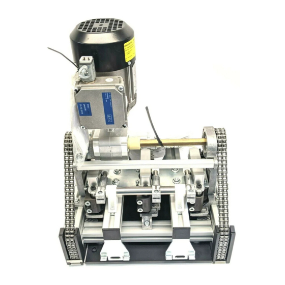
Position (2x) (2x) (3x) monitoring kit (2x) (3x) (2x) (included in the (2x) scope of delivery) (3x) (2x) (2x) (3x) (2x) 562 240-02 Fig. 2: HQ 2/U-H lift transverse unit Bosch Rexroth AG, MIT: HQ 2/U-H, 3 842 562 241/2019-04... - Page 15 4 lift units 4 lift units = 640 mm 3 lift units 4 lift units 4 lift units Fig. 3: Number and arrangement of the lift units for sizes … 3 842 562 241/2019-04, MIT: HQ 2/U-H, Bosch Rexroth AG...
-
Page 16: Identifi Cation Of The Product
• Protect the product from environmental infl uences such as dirt and humidity. • Observe the ambient conditions, see page 64. • Support the product so that there is no load on motors that are installed in a suspended position. Bosch Rexroth AG, MIT: HQ 2/U-H, 3 842 562 241/2019-04... -
Page 17: Assembly
• Hex socket wrenches SW3, SW4, SW5. • Hex socket wrench (Torx™) T30, T50 • Posidriv screwdriver, PZ2 • Hammer • Level • Combination pliers • Flat smooth fi le 3 842 562 241/2019-04, MIT: HQ 2/U-H, Bosch Rexroth AG... -
Page 18: Symbols Used
Graphical depiction of the designation of components. The letters denote the components mentioned in the accompanying text. Detail view from a different direction, for example, the back or the bottom side of the product. Bosch Rexroth AG, MIT: HQ 2/U-H, 3 842 562 241/2019-04... -
Page 19: Installing The Product
Install the T-bolts. Install the cover sheet. SW13 = 25 Nm =22 Nm SW13 = 25 Nm 562 240-03 Fig. 5: Installing the HQ 2/U-H lift transverse unit, b = 240 mm 3 842 562 241/2019-04, MIT: HQ 2/U-H, Bosch Rexroth AG... - Page 20 SW13 Install the T-bolts. = 25 Nm Install the cover sheet. SW13 = 25 Nm 562 240-04 Fig. 6: Installing the HQ 2/U-H lift transverse unit, b ≥ 320 mm Bosch Rexroth AG, MIT: HQ 2/U-H, 3 842 562 241/2019-04...
-
Page 21: Installing The Position Monitoring Device
Not included in the scope of delivery! =7 Nm =1 Nm =7 Nm =2,5 Nm 562 240-50 Fig. 7: Installing the position monitoring device, b = 240 mm, center position 3 842 562 241/2019-04, MIT: HQ 2/U-H, Bosch Rexroth AG... - Page 22 Not included in the scope of delivery! =7 Nm =1 Nm =7 Nm =2,5 Nm 562 240-51 Fig. 8: Installing the position monitoring device, b = 240 mm, upper position / lower position Bosch Rexroth AG, MIT: HQ 2/U-H, 3 842 562 241/2019-04...
- Page 23 ) 3 842 549 814 Not included in the scope of delivery! =2,5 Nm =1 Nm =7 Nm 562 240-52 Fig. 9: Installing the position monitoring device, b ≥ 320 mm, center position 3 842 562 241/2019-04, MIT: HQ 2/U-H, Bosch Rexroth AG...
- Page 24 Not included in the scope of delivery! =7 Nm =1 Nm =2,5 Nm =7 Nm 562 240-53 Fig. 10: Installing the position monitoring device, b ≥ 320 mm, center position Bosch Rexroth AG, MIT: HQ 2/U-H, 3 842 562 241/2019-04...
-
Page 25: Option To Query The Position Of The Workpiece Pallet From Below
562 240-06 Fig. 11: Query the position of the workpiece pallet from below Please note: The query from below is not possible with WT 2/H or WT 2/F-H. 3 842 562 241/2019-04, MIT: HQ 2/U-H, Bosch Rexroth AG... -
Page 26: Installing The Da 2/100-E Damper (Optional)
WT 2: position of the damper when operating with WT 2/H, WT 2/F-H: ≥ 400 mm (mm) X (mm) 562 240-07 Fig. 12: Installing the DA 2/100-E damper (optional) Bosch Rexroth AG, MIT: HQ 2/U-H, 3 842 562 241/2019-04... - Page 27 “+” to make the damping harder. Turn it in the direction marked “–” to make the – damping softer. 562 240-09 Fig. 14: Adjusting the damping in the DA 2/100-E damper 3 842 562 241/2019-04, MIT: HQ 2/U-H, Bosch Rexroth AG...
-
Page 28: Installing The Da 2/150-E Damper (Optional)
WT 2: position of the damper when operating with WT 2/H, WT 2/F-H: SW13 (mm) X (mm) ≥ 400 mm 562 240-10 Fig. 15: Installing the DA 2/150-E damper (optional) Bosch Rexroth AG, MIT: HQ 2/U-H, 3 842 562 241/2019-04... - Page 29 HQ = enabling the damper (pressure pulse, damper Ø 6x1 mm l < 800 mm extends). 4-6 bar 562 240-08 150-E Fig. 16: Pneumatic diagram for the DA 2/ damper 3 842 562 241/2019-04, MIT: HQ 2/U-H, Bosch Rexroth AG...
-
Page 30: Installing The Lu 2 Automatic Lubrication Unit (Optional)
(button in the PLC control) until lubrication comes out of the lubrication pin. 562 240-11 Fig. 17: Installing the HQ 2/U-H adapter set Bosch Rexroth AG, MIT: HQ 2/U-H, 3 842 562 241/2019-04... -
Page 31: Making The Pneumatic Connection To The Product
(without pressurization) to the upper or lower position (TFE 3, TFE 4). You can fi nd the function plans (TFE …) for control tasks in transfer systems in the appendix starting on page 65. 3 842 562 241/2019-04, MIT: HQ 2/U-H, Bosch Rexroth AG... - Page 32 (TFE 4). 562 240-17 Fig. 20: TFE 3, TFE 4 562 240-14 Fig. 22: Pneumatic diagram b [mm]: 320 x …, 400 x …, 3 lift units Bosch Rexroth AG, MIT: HQ 2/U-H, 3 842 562 241/2019-04...
- Page 33 WT from the longitudinal section to the transverse section (TFE 3) or infeed from the transverse section to the longitudinal section (TFE 4). 562 240-17 Fig. 24: TFE 3, TFE 4 3 842 562 241/2019-04, MIT: HQ 2/U-H, Bosch Rexroth AG...
-
Page 34: Adjusting The Lifting Speed
Turn it in the direction marked “-” to make the upward stroke faster. 562 240-47 Fig. 26: Adjusting the lifting speed b [mm]: 240 x …, 2 lift units Bosch Rexroth AG, MIT: HQ 2/U-H, 3 842 562 241/2019-04... - Page 35 Turn it in the direction marked “-” to make the upward stroke faster. – 562 240-48 Fig. 27: Adjusting the lifting speed b [mm]: 320 x …, 400 x …, 3 lift units 3 842 562 241/2019-04, MIT: HQ 2/U-H, Bosch Rexroth AG...
- Page 36 Turn it in the direction marked “-” to make the upward stroke faster. – 562 240-48 Fig. 28: Adjusting the lifting speed b [mm]: 480 x …, 640 x …, 4 lift units Bosch Rexroth AG, MIT: HQ 2/U-H, 3 842 562 241/2019-04...
-
Page 37: Making The Electrical Connection To The Product
Please note: For motors that come with a fi tted plug, correct the rotational direction in the control cabinet or at the socket contact (socket side). This makes replacement easier. 3 842 562 241/2019-04, MIT: HQ 2/U-H, Bosch Rexroth AG... - Page 38 38/72 Assembly Installation_A Fig. 29: Motor nameplate (example) Installation_DY Fig. 30: Delta/wye connection diagrams Installation_IEC Fig. 31: Optional motor connection with plug (AT = S) Bosch Rexroth AG, MIT: HQ 2/U-H, 3 842 562 241/2019-04...
- Page 39 The plug connection consists of UL components. Connection list Connection Code terminals, motor 3~ Installation_Stecker Fig. 33: Motor connection with plug (AT = 1), plug connection A: Connection cable side B: Motor side 3 842 562 241/2019-04, MIT: HQ 2/U-H, Bosch Rexroth AG...
-
Page 40: Installing The Protective Casing
Make sure you install the lock washer (A, 3 842 542 330) as a locking device for the screws! =2,5 Nm =4 Nm 562 240-46 Fig. 34: Preassembling the protective casing Bosch Rexroth AG, MIT: HQ 2/U-H, 3 842 562 241/2019-04... - Page 41 HQ 2/U-H from below. Screw it together with the section. Please note: Motor connection with plug: (mm) (mm) =7 Nm 562 240-19 Fig. 35: Installing the protective casing 3 842 562 241/2019-04, MIT: HQ 2/U-H, Bosch Rexroth AG...
- Page 42 Cut out the marked cutouts with a saw. Smooth the saw burrs with a fi le. = 320 mm ≥ 400 mm 562 240-20 Fig. 36: Cutouts for mounting the damper Bosch Rexroth AG, MIT: HQ 2/U-H, 3 842 562 241/2019-04...
- Page 43 Cutouts for mounting the connection kits Cut out the marked cutouts with a saw. Smooth the saw burrs with a fi le. 562 240-21 Fig. 37: Cutouts for mounting the connection kits 3 842 562 241/2019-04, MIT: HQ 2/U-H, Bosch Rexroth AG...
-
Page 44: Initial Lubrication Of The Conveyor Chain
GHD, 0 842 904 229. Required lubricant quantity: 2 g/m chain length Size b Chain [mm] length [m] 0.75 0.86 0.98 562 240-22 1.12 Fig. 38: Initial lubrication of the conveyor chain 1.41 Bosch Rexroth AG, MIT: HQ 2/U-H, 3 842 562 241/2019-04... -
Page 45: Start-Up
• Only start up the product if all safety equipment has been installed in the system and is functional. • Only start up a product that has been completely installed. 3 842 562 241/2019-04, MIT: HQ 2/U-H, Bosch Rexroth AG... - Page 46 Failure of one (or more) of its components or supply devices External disturbances (e.g. impact, vibration, electromagnetic interference) Design faults or defects (e.g. software errors) Disruption in the power supply Environmental conditions (e.g. damaged fl oors) Bosch Rexroth AG, MIT: HQ 2/U-H, 3 842 562 241/2019-04...
-
Page 47: Residual Risks
Secure the danger zone adequately. ) Life stages of the machine according to EN 12100 Sect. 5.4 a /b (No. 1- 27), Sect. 5.4 a (see page 46) 562 240-23 3 842 562 241/2019-04, MIT: HQ 2/U-H, Bosch Rexroth AG... -
Page 48: Re-Commissioning After A Standstill
The modular units are designed and tested under the assumption that the workpiece pallets will not all have the same weight during one cycle on one conveyor section. Workpiece pallets are both loaded and unloaded. Bosch Rexroth AG, MIT: HQ 2/U-H, 3 842 562 241/2019-04... -
Page 49: Environmental Factors
In such instances, special care must be taken when planning the system, and the maintenance intervals must be correspondingly shortened. 3 842 562 241/2019-04, MIT: HQ 2/U-H, Bosch Rexroth AG... -
Page 50: Maintenance And Repair
There is a risk of damage to property. Keep degreasers or aggressive cleaning agents away from the chain! Only clean the product with a damp cloth. Bosch Rexroth AG, MIT: HQ 2/U-H, 3 842 562 241/2019-04... -
Page 51: Inspection
10.4 Replacement of wear parts Required tools • Hex wrench (open-end) SW13 • Hex socket wrenches SW3, SW4, SW5 • Posidriv screwdriver, PZ2 • Caliper, 500 mm • Rubber mallet • Drift punch 3 842 562 241/2019-04, MIT: HQ 2/U-H, Bosch Rexroth AG... -
Page 52: Opening The Protective Casing
=4 Nm protective casing. 562 240-24 Fig. 39: Opening the protective casing Bosch Rexroth AG, MIT: HQ 2/U-H, 3 842 562 241/2019-04... -
Page 53: Replacing The Roller Chain
• Fix this setting with the SW13 screws (B). = 22 Nm 562 240-25 Fig. 40: Replacing the roller chain 3 842 562 241/2019-04, MIT: HQ 2/U-H, Bosch Rexroth AG... -
Page 54: Replacing The Chain Guide
Install the chain guide in reverse order. Note the installation position of the chain guide (F). SW13 = 25 Nm 562 240-26 Fig. 41: Replacing the chain guide Bosch Rexroth AG, MIT: HQ 2/U-H, 3 842 562 241/2019-04... -
Page 55: Replacing The Motor And/Or Gear
• Install the motor in the proper position (terminal box) and connect it to the gear. If the motor is not in the proper position: do NOT rotate the motor. Disconnect the motor from the gear and reconnect it. 3 842 562 241/2019-04, MIT: HQ 2/U-H, Bosch Rexroth AG... -
Page 56: Replacing The Block Cylinder: 2 Block Cylinders
Remove the motor-gear combination. Remove the cover plate. Remove the parallel guide. =8 Nm SW13 =22 Nm =8 Nm 562 240-28 Fig. 43: Replacing the block cylinder: 2 block cylinders (1/2) Bosch Rexroth AG, MIT: HQ 2/U-H, 3 842 562 241/2019-04... - Page 57 (Y)! Replace the block cylinders. Install the block cylinders in reverse order. =8 Nm SW13 562 240-29 Fig. 44: Replacing the block cylinder: 2 block cylinders (2/2) 3 842 562 241/2019-04, MIT: HQ 2/U-H, Bosch Rexroth AG...
- Page 58 Remove the motor-gear combination. Remove the cover plate. Remove the parallel guide. SW13 =22 Nm =8 Nm =8 Nm 562 240-30 Fig. 45: Replacing the block cylinder: 3 block cylinders (1/2) Bosch Rexroth AG, MIT: HQ 2/U-H, 3 842 562 241/2019-04...
- Page 59 (Y)! Replace the block cylinders. Install the block cylinders in reverse order. SW13 =8 Nm 562 240-31 Fig. 46: Replacing the block cylinder: 3 block cylinders (2/2) 3 842 562 241/2019-04, MIT: HQ 2/U-H, Bosch Rexroth AG...
- Page 60 (see page 53). Remove the motor-gear combination. Remove the cover plate. Remove the parallel guide. =8 Nm =8 Nm 562 240-32 Fig. 47: Replacing the block cylinder: 4 block cylinders (1/2) Bosch Rexroth AG, MIT: HQ 2/U-H, 3 842 562 241/2019-04...
- Page 61 Install the block cylinders in reverse order. = 480 mm = 640 mm 75,5 82,5 =8 Nm SW13 562 240-33 Fig. 48: Replacing the block cylinder: 4 block cylinders (2/2) 3 842 562 241/2019-04, MIT: HQ 2/U-H, Bosch Rexroth AG...
-
Page 62: Spare Parts
• Protect the product from environmental infl uences such as dirt and humidity. • Observe the ambient conditions, see page 64. • For products with a mounted motor: support the product so that the motor is not placed under mechanical load. Bosch Rexroth AG, MIT: HQ 2/U-H, 3 842 562 241/2019-04... -
Page 63: Disposal
14 Upgrading and modifi cation • Do not modify the product. • The Bosch Rexroth warranty only applies to the confi guration as delivered, and to approved upgrades. The manufacturer will not accept any warranty claims for systems with unapproved modifi cations or upgrades. -
Page 64: Ambient Conditions
) The pressure dew point should be at least 15 °C below the ambient temperature. • Oil content – Oil quantity ≤ 1 mg/m (Class 3 as per ISO 8573-1:2010) Bosch Rexroth AG, MIT: HQ 2/U-H, 3 842 562 241/2019-04... -
Page 65: Appendix
Y … = Valve Z … = Cylinder = Longitudinal conveyor (main section) = Transverse conveyor (secondary section) = Start pulse after end of start-up = Enable cyclic travel 3 842 562 241/2019-04, MIT: HQ 2/U-H, Bosch Rexroth AG... -
Page 66: Implementation In Transverse Section (Tfe 1)
562 240-39 = WT after VE4 (Z4) = WT in position on HQ (WI/M rocker) = Delaying time 100…200 ms = HQ lift cylinder (Z3) = Secondary section VE (Z4) Bosch Rexroth AG, MIT: HQ 2/U-H, 3 842 562 241/2019-04... -
Page 67: Transverse Conveyor (Separating, Outfeeding) (Tfe 3)
= Enable secondary section = Main section VE (Z1) = HQ lift cylinder (Z2) P10 = Priority main section = Identifi cation system with straight-ahead signal (0 = branching, 1 = straight) 3 842 562 241/2019-04, MIT: HQ 2/U-H, Bosch Rexroth AG... -
Page 68: Transverse Conveyor (Separating, Infeeding) (Tfe 4)
= Delaying time 100…200 ms = HQ lift cylinder (Z3) = Secondary section VE (Z4) = Main section VE (Z5) = VE in HQ (Z6) P10 = Priority main section Bosch Rexroth AG, MIT: HQ 2/U-H, 3 842 562 241/2019-04... - Page 69 Appendix 69/72 3 842 562 241/2019-04, MIT: HQ 2/U-H, Bosch Rexroth AG...
- Page 70 70/72 Bosch Rexroth AG, MIT: HQ 2/U-H, 3 842 562 241/2019-04...
- Page 71 71/72 3 842 562 241/2019-04, MIT: HQ 2/U-H, Bosch Rexroth AG...
- Page 72 Bosch Rexroth AG Postfach 30 02 07 70442 Stuttgart Germany Fax +49 711 811–7777 info@boschrexroth.de www.boschrexroth.com Subject to change 3 842 562 241/2019-04...