
Related Manuals for Siemens SIMATIC NET RUGGEDCOM RX1524


Summary of Contents for Siemens SIMATIC NET RUGGEDCOM RX1524
- Page 1 Edition 10/2021 Installation Manual SIMATIC NET Rugged Multi Service Platforms RUGGEDCOM RX1524 https://www.siemens.com/ruggedcom...
- Page 2 Preface Introduction Installing the Device SIMATIC NET Device Management Rugged Multi Service Platforms RUGGEDCOM RX1524 Modules Technical Specifications Installation Manual Certification 10/2021 C79000-G8976-1487-03...
- Page 3 Note the following: WARNING Siemens products may only be used for the applications described in the catalog and in the relevant technical documentation. If products and components from other manufacturers are used, these must be recommended or approved by Siemens. Proper transport, storage, installation, assembly, commissioning, operation and maintenance are required to ensure that the products operate safely and without any problems.
-
Page 4: Table Of Contents
Accessing Documentation ....................... v Registered Trademarks ......................v Warranty ..........................vi Training ..........................vi Customer Support ........................vii Contacting Siemens ....................... vii Introduction ........................... 1 Feature Highlights ....................1 Description ......................1 Required Tools and Materials ................. 2 Decommissioning and Disposal ................3 Cabling Recommendations .................. - Page 5 Table of Contents Technical Specifications ...................... 31 Power Supply Specifications ................31 Failsafe Relay Specifications ................31 Operating Environment ..................32 Mechanical Specifications ..................32 Dimension Drawings ................... 32 Certification ......................... 37 Approvals ......................37 6.1.1 TÜV SÜD ......................37 6.1.2 European Union (EU) ..................
-
Page 6: Preface
SIMATIC NET Glossary The SIMATIC NET Glossary describes special terms that may be used in this document. The glossary is available online via Siemens Industry Online Support (SIOS) at: https://support.industry.siemens.com/cs/ww/en/view/50305045 Accessing Documentation The latest user documentation for RUGGEDCOM RX1524 is available online at https:// support.industry.siemens.com. -
Page 7: Warranty
Warranty Siemens warrants this product for a period of five (5) years from the date of purchase, conditional upon the return to factory for maintenance during the warranty term. This product contains no user-serviceable parts. Attempted service by unauthorized personnel shall render all warranties null and void. -
Page 8: Customer Support
Preface Customer Support Customer Support Customer support is available 24 hours, 7 days a week for all Siemens customers. For technical support or general information, contact Siemens Customer Support through any of the following methods: Online Visit http://www.siemens.com/automation/support-request to submit a Support Request (SR) or check on the status of an existing SR. - Page 9 Preface Contacting Siemens viii RUGGEDCOM RX1524 Installation Manual, 10/2021, C79000-G8976-1487-03...
-
Page 10: Introduction
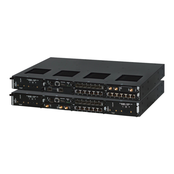
Introduction The RUGGEDCOM RX1524 is a cost-efficient, rugged Layer 3 switch and router. The RUGGEDCOM RX1524’s modular and field replaceable platform can be equipped with WAN, serial, and Ethernet options, making it ideally suited for electric power utilities, the industrial plant floor, and traffic control systems. The RUGGEDCOM RX1524 is designed to provide a high level of immunity to electromagnetic interference (EMI) and heavy electrical surges typical of the harsh environments found in many industrial applications. -
Page 11: Required Tools And Materials
Introduction 1.3 Required Tools and Materials Management Port RS232 Serial Console Port (DB9) Utility USB Port Port Status LEDs Power Status LEDs Alarm Indicator LED Lamp Test/Alarm Cut-Off (LT/ACO) Button Figure 1.1 RUGGEDCOM RX1524 Management Port This 10/100Base-T Ethernet port is used for system management that is out-of-band from the switch fabric. -
Page 12: Decommissioning And Disposal
Recycling and disposal must be done in accordance with local regulations. Cabling Recommendations Siemens recommends using SIMATIC NET industrial Ethernet shielded cables for all Ethernet ports. 1.5.1 Protection On Twisted-Pair Data Ports... -
Page 13: Gigabit Ethernet 1000Base-Tx Cabling Recommendations
Siemens also does not recommend using copper Ethernet ports to interface with devices in the field across distances that could produce high levels of ground potential rise (i.e. greater than 2500 V), during line-to-ground fault conditions. -
Page 14: Installing The Device
Installing the Device This chapter describes how to install the device, including mounting the device, connecting power, and connecting the device to the network. DANGER Electrocution hazard – risk of serious personal injury and/or damage to equipment. Before performing any maintenance tasks, make sure all power to the device has been disconnected and wait approximately two minutes for any remaining energy to dissipate. -
Page 15: General Procedure
This product contains no user-serviceable parts. Attempted service by unauthorized personnel shall render all warranties null and void. Changes or modifications not expressly approved by Siemens Canada Ltd. could invalidate specifications, test results, and agency approvals, and void the user's authority to operate the equipment. -
Page 16: Mounting The Device
2.3 Mounting the Device Verify all items are included. Note If any item is missing or damaged, contact Siemens for assistance. Mounting the Device The RUGGEDCOM RX1524 is designed for maximum mounting and display flexibility. It can be equipped with connectors that allow it to be installed in a 48 cm (19 in) rack, 35 mm (1.4 in) DIN rail or directly on a panel. -
Page 17: Mounting The Device On A Din Rail
Installing the Device 2.3.2 Mounting the Device on a DIN Rail • Do not exceed the maximum number of devices or weight restrictions specified by the rack manufacturer. • Do not overload the supply circuit. Refer to the over-current protection and power supply ratings specified by the rack manufacturer. -
Page 18: Mounting The Device To A Panel
Installing the Device 2.3.3 Mounting the Device to a Panel To mount the device to a DIN rail, do the following: Align the adapters with the DIN rails and slide the device into place. Panel/DIN Rail Adapter DIN Rail Screw Figure 2.2 DIN Rail Mounting Install one of the supplied screws on either side of the device to secure the adapters to the DIN rails. -
Page 19: Connecting The Failsafe Alarm Relay
Installing the Device 2.4 Connecting the Failsafe Alarm Relay To mount the device to a panel, do the following: Place the device against the panel and mark the mounting holes on the panel. Screw Panel/DIN Rail Adapter Figure 2.3 Panel Mounting Prepare the mounting holes Align the device with the mounting holes and secure it to the panel. -
Page 20: Connecting Power
Installing the Device 2.5 Connecting Power Normally Open Common Normally Closed Figure 2.4 Failsafe Alarm Relay Wiring Connecting Power Power modules can be equipped with either a screw or European-style (Euroblock) terminal block. The screw terminal block is installed using Phillips screws and compression plates, allowing either bare wire connections or crimped terminal lugs. -
Page 21: Connecting High Ac/Dc Power
Installing the Device 2.5.1 Connecting High AC/DC Power 2.5.1 Connecting High AC/DC Power To connect a high AC/DC power supply to the device, do the following: DANGER Electrocution hazard – risk of death, serious personal injury and/or damage to the device Make sure the supplied cover is always installed over high voltage screw terminal blocks. - Page 22 Installing the Device 2.5.1 Connecting High AC/DC Power Connect the power supply terminal block to the device. European-style (Euroblock) Terminal Block Positive/Live (+/L) Terminal Ground Terminal Negative/Neutral (-/N) Terminal Figure 2.5 AC Terminal Block Wiring – European-style (Euroblock) Terminal Block for HIP Power Supplies Not Connected Removable Screw Terminal Block...
- Page 23 Installing the Device 2.5.1 Connecting High AC/DC Power Negative/Neutral (-/N) Terminal Figure 2.6 AC Terminal Block Wiring – Screw Terminal Block for HI Power Supplies Note For secure, reliable connections under severe shock or vibration, use M3.5 ring lugs with a maximum outer diameter of 7 mm (0.28 in). Make sure no bare metal is exposed beyond the safety cover.
-
Page 24: Connecting Low Dc Power
Installing the Device 2.5.2 Connecting Low DC Power Using a #10 ring lug and #10-32 screw, secure the ground terminal on the power source to the ground connection on the device. Make sure the lug is tightened to 1.1 N·m (9.5 lbf·in). #10 Ring Lug #10-32 Screw Connection from External Power Source... - Page 25 Installing the Device 2.5.2 Connecting Low DC Power Connect the power supply terminal block to the device. European-style (Euroblock) Terminal Block Positive (+) Terminal Negative (-) Terminal Ground Terminal Figure 2.9 DC Terminal Block Wiring – European-style (Euroblock) Terminal Block for 12P, 24P and 48P Power Supplies Not Connected Removable Screw Terminal Block...
- Page 26 Installing the Device 2.5.2 Connecting Low DC Power Ground Terminal Figure 2.10 DC Terminal Block Wiring – Screw Terminal Block for 12P, 24P and 48P Power Supplies European-style (Euroblock) Terminal Block Positive (+) Terminal Negative (-) Terminal Ground Terminal Figure 2.11 DC Terminal Block Wiring – European-style (Euroblock) Terminal Block for -12P, -24P and -48P Power Supplies Not Connected Removable Screw Terminal Block...
- Page 27 Installing the Device 2.5.2 Connecting Low DC Power Ground Terminal Figure 2.12 DC Terminal Block Wiring – Screw Terminal Block for -12P, -24P and -48P Power Supplies Note For secure, reliable connections under severe shock or vibration, use M3.5 ring lugs with a maximum outer diameter of 7 mm (0.28 in). Make sure no bare metal is exposed beyond the safety cover.
- Page 28 Installing the Device 2.5.2 Connecting Low DC Power Using a #10 ring lug and #10-32 screw, secure the ground terminal on the power source to the ground connection on the device. Make sure the lug is tightened to 2.4 N·m (21 lbf·in). #10 Ring Lug #10-32 Screw Connection from External Power Source...
- Page 29 Installing the Device 2.5.2 Connecting Low DC Power RUGGEDCOM RX1524 Installation Manual, 10/2021, C79000-G8976-1487-03...
-
Page 30: Device Management
It may cause damage to the contact pins of the RJ45 ports. For a permanent solution, use Siemens 6XV1870-3Qxxx certified cables (manufactured December 2019 or after) or equivalent. Siemens recommends using Siemens certified cables and connectors for Siemens RUGGEDCOM products. - Page 31 Device Management 3.1 Connecting to the Device Serial Console and Management Ports Connect a workstation directly to the serial console or management ports to access the boot-time control and RUGGEDCOM RX1524 interfaces. The serial console port provides access to RUGGEDCOM RX1524's console interface, while the management port provides access to RUGGEDCOM RX1524's console and Web interfaces.
-
Page 32: Configuring The Device
Device Management 3.2 Configuring the Device Note Single-mode fiber ports only support Ultra Physical Contact (UPC) cable connectors. Configuring the Device Once the device is installed and connected to the network, it must be configured. All configuration management is done via the RUGGEDCOM RX1524 interface. For more information about configuring the device, refer to the "RUGGEDCOM ROX Configuration Manual"... - Page 33 Device Management 3.2 Configuring the Device RUGGEDCOM RX1524 Installation Manual, 10/2021, C79000-G8976-1487-03...
-
Page 34: Modules
Up to two RUGGEDCOM APE modules are supported Figure 4.1 Available Chassis Slots Available Modules A variety of modules are available for use with the RUGGEDCOM RX1524. For more information, refer to the "RUGGEDCOM Modules Catalog [https:// support.industry.siemens.com/cs/us/en/view/109747072]" for the RUGGEDCOM RX1524. RUGGEDCOM RX1524 Installation Manual, 10/2021, C79000-G8976-1487-03... -
Page 35: Installing/Removing Line Modules
Modules 4.3 Installing/Removing Line Modules Installing/Removing Line Modules Upon installing a new line module in the device, all features associated with the module are available in RUGGEDCOM RX1524. For more information, refer to the "RUGGEDCOM ROX Configuration Manual" for the RUGGEDCOM RX1524. Once a line module is removed, all the features associated with the module are hidden or disabled in RUGGEDCOM RX1524. - Page 36 Modules 4.3 Installing/Removing Line Modules Pull the module from the chassis to disconnect it. Module Chassis Screw Figure 4.2 Removing a Module Install a new module or a blank module (to prevent the ingress of dust and dirt). [Optional] If necessary, install the device in the rack. Installing a Module To install a line module, do the following: [Optional] If the device is installed in a rack, remove it from the rack.
-
Page 37: Installing/Removing Power Modules
Modules 4.4 Installing/Removing Power Modules Installing/Removing Power Modules Figure 4.4 NOTICE Contamination hazard – risk of equipment damage Prevent the ingress of water, dirts and other debris that may lead to premature equipment failure. Always make sure slots are not left empty. Removing a Power Module To remove a power module, do the following: DANGER... - Page 38 Modules 4.4 Installing/Removing Power Modules Install a new or blank module to prevent the ingress of dust and dirt. Installing a Power Module To install a power module, do the following: If equipped, remove the existing module. If applicable, connect the supplied terminal block to the module or connect the terminal block from the previous module.
- Page 39 Modules 4.4 Installing/Removing Power Modules RUGGEDCOM RX1524 Installation Manual, 10/2021, C79000-G8976-1487-03...
-
Page 40: Technical Specifications
Technical Specifications This section provides important technical specifications related to the device. Power Supply Specifications Note When determining cable lengths, make sure the minimum input voltage for the power supply is provided at the power source. Input Range Maximum Power Internal Power Insulation... -
Page 41: Operating Environment
Technical Specifications 5.3 Operating Environment Operating Environment The RUGGEDCOM RX1524 is rated to operate under the following environmental conditions. Note Temperature limits for select line modules may differ from that which can be withstood by the RUGGEDCOM RX1524. Make sure the selected modules are rated for the expected environmental conditions before deployment. - Page 42 Technical Specifications 5.5 Dimension Drawings 440.9 Figure 5.1 Overall Dimensions RUGGEDCOM RX1524 Installation Manual, 10/2021, C79000-G8976-1487-03...
- Page 43 Technical Specifications 5.5 Dimension Drawings 21.1 463.8 11.7 Figure 5.2 Rack Mount Dimensions 479.0 21.1 11.7 489.2 Figure 5.3 Panel and Din Rail Mount Dimensions RUGGEDCOM RX1524 Installation Manual, 10/2021, C79000-G8976-1487-03...
- Page 44 Technical Specifications 5.5 Dimension Drawings 162.5 151.4 19.7 Figure 5.4 Line Module Dimensions 162.5 151.8 40.6 Figure 5.5 Power Module Dimensions RUGGEDCOM RX1524 Installation Manual, 10/2021, C79000-G8976-1487-03...
- Page 45 Technical Specifications 5.5 Dimension Drawings RUGGEDCOM RX1524 Installation Manual, 10/2021, C79000-G8976-1487-03...
-
Page 46: Certification
UL 62368-1 Information Technology Equipment – Safety – Part 1: General Requirements 6.1.2 European Union (EU) This device is declared by Siemens Canada Ltd. to comply with essential requirements and other relevant provisions of the following EU directives: • Directive 2014/30/EU... - Page 47 The device is marked with a CE marking and notified body number, and can be used throughout the European community. 0680 A copy of the CE Declaration of Conformity is available from Siemens Canada Ltd.. For contact information, refer to "Contacting Siemens (Page vii)".
-
Page 48: Fcc
Title 21 Code of Federal Regulations (CFR) – Chapter I – Sub-chapter J – Radiological Health 6.1.5 ISED This device is declared by Siemens Canada Ltd. to meet the requirements of the following ISED (Innovation Science and Economic Development Canada) standard: • CAN ICES-3 (A)/NMB-3 (A) 6.1.6... -
Page 49: Other Approvals
China RoHS 2 Administrative Measure on the Control of Pollution Caused by Electronic Information Products A copy of the Material Declaration is available online at https:// support.industry.siemens.com/cs/ww/en/view/109738831. 6.1.8 Other Approvals This device meets the requirements of the following additional standards: •... - Page 50 5 kV (Failsafe Relay output) DC Power Ports 5 kV AC Power Ports Siemens-specified severity levels. EMC Immunity Type Tests for IEEE 1613 Note The RUGGEDCOM RX1524 meets Class 2 requirements for an all-fiber configuration and Class 1 requirements for copper ports. Class 1 allows for temporary communication loss, while Class 2 requires error-free and interrupted communications.
- Page 51 Certification 6.2 EMC and Environmental Type Tests Description Test Levels Dielectric Strength Signal ports 2 kV DC Power Ports 1.5 kV AC Power Ports 2 kV Fast Transient Signal ports ± 4 kV @ 2.5 kHz DC Power Ports ± 4 kV AC Power Ports Earth ground ports Oscillatory...
- Page 52 For more information Siemens RUGGEDCOM https://www.siemens.com/ruggedcom Industry Online Support (service and support) https://support.industry.siemens.com Industry Mall https://mall.industry.siemens.com Siemens Canada Ltd. Digital Industries Process Automation 300 Applewood Crescent Concord, Ontario, L4K 4E5 Canada © 2021 Siemens Canada Ltd. Subject to change...