Table of Contents
Advertisement
Quick Links
SCALANCE W788-x / W748-1
SIMATIC NET
Industrial Wireless LAN
SCALANCE W788-x / W748-1
Operating Instructions
03/2022
A5E03678333-17
Introduction
Safety notices
Security
recommendations
Description of the device
Installation and removal
Connecting up
Maintenance and cleaning
Troubleshooting
Technical specifications
Dimension drawings
Certification
1
2
3
4
5
6
7
8
9
10
11
Advertisement
Table of Contents

Related Manuals for Siemens SIMATIC NET SCALANCE W788-x


Summary of Contents for Siemens SIMATIC NET SCALANCE W788-x
- Page 1 SCALANCE W788-x / W748-1 Introduction Safety notices Security SIMATIC NET recommendations Description of the device Industrial Wireless LAN SCALANCE W788-x / W748-1 Installation and removal Connecting up Operating Instructions Maintenance and cleaning Troubleshooting Technical specifications Dimension drawings Certification 03/2022 A5E03678333-17...
- Page 2 Note the following: WARNING Siemens products may only be used for the applications described in the catalog and in the relevant technical documentation. If products and components from other manufacturers are used, these must be recommended or approved by Siemens. Proper transport, storage, installation, assembly, commissioning, operation and maintenance are required to ensure that the products operate safely and without any problems.
-
Page 3: Table Of Contents
Table of contents Introduction ............................. 5 Safety notices ............................9 Security recommendations ........................11 Description of the device ........................19 Structure of the type designations ..................... 19 Device view ............................ 20 4.2.1 SCALANCE W7x8-x RJ45 ......................20 4.2.2 SCALANCE W7x8-x M12 ......................21 Components of the product ...................... - Page 4 Table of contents Digital input/output ........................57 Grounding ............................57 Replacing the PLUG ........................58 Maintenance and cleaning ........................59 Troubleshooting ............................ 61 Device configuration with PRESET-PLUG ................61 Restoring the factory settings ..................... 63 Firmware update via WBM or CLI not possible ................ 65 Technical specifications........................
-
Page 5: Introduction
Introduction Validity of the Operating Instructions These operating instructions cover the following products: Product Article number Article number Article number US version Israel version Access points SCALANCE W788-1 RJ-45 6GK5788-1FC00-0AA0 6GK5788-1FC00-0AB0 SCALANCE W788-1 M12 6GK5788-1GD00-0AA0 6GK5788-1GD00-0AB0 Dual access points SCALANCE W788-2 RJ-45 6GK5788-2FC00-0AA0 6GK5788-2FC00-0AB0 6GK5788-2FC00-0AC0... - Page 6 "DC_support_99.pdf" on the data medium supplied with the documentation. Security information Siemens provides products and solutions with industrial security functions that support the secure operation of plants, systems, machines and networks. In order to protect plants, systems, machines and networks against cyber threats, it is necessary to implement –...
- Page 7 Firmware The firmware is signed and encrypted. This ensures that only firmware created by Siemens can be downloaded to the device. The firmware is available on the Internet pages of the Siemens Industry Online Support: (https://support.industry.siemens.com/cs/de/en/ps/15860/dl) Note on firmware/software support Check regularly for new firmware/software versions or security updates and apply them.
- Page 8 Introduction Trademarks The following and possibly other names not identified by the registered trademark sign ® are registered trademarks of Siemens AG: SCALANCE, C-PLUG, RCoax SCALANCE W788-x / W748-1 Operating Instructions, 03/2022, A5E03678333-17...
-
Page 9: Safety Notices
Safety notices CAUTION To prevent injury and damage, read the manual before using the device. Read the safety notices Note the following safety notices. These relate to the entire working life of the device. You should also read the safety notices relating to handling in the individual sections, particularly in the sections "Installation"... - Page 10 Safety notices SCALANCE W788-x / W748-1 Operating Instructions, 03/2022, A5E03678333-17...
-
Page 11: Security Recommendations
OpenVPN). • Separate connections correctly (WBM, SSH etc.). • Check the user documentation of other Siemens products that are used together with the device for additional security recommendations. • Using remote logging, ensure that the system protocols are forwarded to a central logging server. - Page 12 Security recommendations • Replace the default passwords for all user accounts, access modes and applications (if applicable) before you use the device. • Define rules for the assignment of passwords. • Use passwords with a high password strength. Avoid weak passwords, (e.g. password1, 123456789, abcdefgh) or recurring characters (e.g.
- Page 13 • Verify certificates based on the fingerprint on the server and client side to prevent "man in the middle" attacks. Use a second, secure transmission path for this. • Before sending the device to Siemens for repair, replace the current certificates and keys with temporary disposable certificates and keys, which can be destroyed when the device is returned.
- Page 14 Security recommendations • Ensure that the latest firmware version is installed, including all security-related patches. You can find the latest information on security patches for Siemens products at the Industrial Security (https://www.siemens.com/industrialsecurity) or ProductCERT Security Advisories (https://www.siemens.com/cert) website. For updates on Siemens product security advisories, subscribe to the RSS feed on the ProductCERT Security Advisories website or follow @ProductCert on Twitter.
- Page 15 Security recommendations Secure/ non-secure protocols • Use secure protocols if access to the device is not prevented by physical protection measures. • Disable or restrict the use of non-secure protocols. While some protocols are secure (e.g. HTTPS, SSH, 802.1X, etc.), others were not designed for the purpose of securing applications (e.g.
- Page 16 Security recommendations List of available services The following is a list of all available services and their ports through which the device can be accessed. The table includes the following columns: • Service The services that the device supports • Default port status This is the status of the port in the delivery state (factory setting).
- Page 17 Security recommendations Service Protocol / Port Default port Configurable Authentication Encryption number status Port Service DHCP Client IPv4 UDP/68 Outgoing only ✓ DHCP Client IPv6 UDP/546 Outgoing only ✓ DHCP Server UDP/67 Closed ✓ DNS Client TCP/53 Outgoing only ✓ UDP/53 EthernetIP TCP/44818...
- Page 18 Security recommendations The following is a list of all available Layer 2 services through which the device can be accessed. The table includes the following columns: • Layer 2 service The Layer 2 services that the device supports. • Default status The default status of the service (open or closed).
-
Page 19: Description Of The Device
Description of the device Structure of the type designations The type designation of a SCALANCE W7x8 is made up of several parts that have the following meaning: SCALANCE W788-x / W748-1 Operating Instructions, 03/2022, A5E03678333-17... -
Page 20: Device View
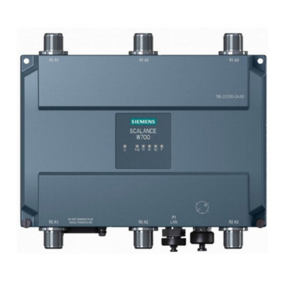
Description of the device 4.2 Device view Device view 4.2.1 SCALANCE W7x8-x RJ45 ① LED display ② Antenna connectors, type R-SMA female • Devices with one IWLAN interface: Three connectors on the top (covered) – • Devices with two IWLAN interfaces: Three connectors on the top (covered) –... -
Page 21: Scalance W7X8-X M12
Description of the device 4.2 Device view 4.2.2 SCALANCE W7x8-x M12 ① Antenna connectors, type R-SMA female • Devices with one IWLAN interface: Three connectors on the top – • Devices with two IWLAN interfaces: Three connectors on the top –... -
Page 22: Components Of The Product
The mounting adapter is not included in the scope of delivery, see Accessories. Please check that the consignment you have received is complete. If the consignment is incomplete, contact your supplier or your local Siemens office. Accessories Technical data subject to change. -
Page 23: Installation
Description of the device 4.4 Accessories Component Description Article number KEY-PLUG W700 Security 6GK5907-0PA00 W700 Security Enabling of “Inter AP Blocking” and exchangeable storage medium for storage of configuration data 4.4.2 Installation Mounting adapter Component Description Article number DIN rail Mounting adapter for installation on the DIN rail 6GK5798-8ML00-0AB3 adapter... -
Page 24: Power Supply
Socket for the 24 VDC power supply. 4-pin, A- 6GK1907-0DC10-6AA3 CABLE coded CONNECTOR pack of 3 4.4.5 Flexible connecting cables, antennas and accessories You will find an overview of the IWLAN products and their accessories in the Order overview (https://support.industry.siemens.com/cs/ww/en/view/109766333). SCALANCE W788-x / W748-1 Operating Instructions, 03/2022, A5E03678333-17... -
Page 25: Flexible Connecting Cables
Description of the device 4.4 Accessories 4.4.5.1 Flexible connecting cables Flexible connecting cable N-Connect/R-SMA Flexible connecting cable for connecting an antenna to a SCALANCE W device with R- SMA connectors, preassembled with an N-Connect male and an R-SMA male connector: Length Article number 0.3 m... -
Page 26: Lightning Protection
Description of the device 4.4 Accessories For railway applications, the following connecting cable is available, scope of delivery 1 unit: Length Article number 6XV1875-5VH10 4.4.5.2 Lightning protection Component Description Article number LP798-1N Lighting protector with N/N 6GK5798-2LP00-2AA6 female/female connector with gas discharge technology LP798-2N Lighting protector with N/N... -
Page 27: Antennas
4.4 Accessories 4.4.5.5 Antennas Note When you select an antenna, keep in mind the national approvals for your device. You can find additional information under Wireless approvals (https://www.siemens.com/wireless-approvals). Type Properties Article number IWLAN RCoax RCoax helical antenna with circular 6GK5792-4DN00-0AA6... - Page 28 Description of the device 4.4 Accessories Type Properties Article number ANT795-4MD Omnidirectional antenna, 3/5 dBi, 2.4 GHz 6GK5795-4MD00-0AA3 and 5 GHz, IP65, N-Connect male for direct installation on the device, 90° connector. ANT795-4MX Omnidirectional antenna, 2/2.5 dBi, 6GK5795-4MX00-0AA0 2.4 GHz and 5 GHz, IP69K, N-Connector male ANT795-6DC Wide angle antenna, mast/wall mounting,...
-
Page 29: Led Display
Description of the device 4.5 LED display LED display Information on operating status and data transfer On the front of the housing, several LEDs provide information on the operating status of the SCALANCE W7x8: LEDs with RJ-45 variants LEDs with M12 variants Note The "R2"... - Page 30 Description of the device 4.5 LED display Color Meaning Flashing green Data transfer over the Ethernet interface P1. and yellow The WLAN interface 1 is deactivated. Access point mode: Green The WLAN interface 1 is initialized and ready for operation. Client mode: There is a connection over the WLAN interface 1.
- Page 31 Description of the device 4.5 LED display Color Meaning Access point mode: Flashing yellow With DFS (802.11h), the channel is scanned for one minute for competing radar signals before the channel can be used for data traffic. Interval: 100 ms on / 100 ms off No fault/error.
-
Page 32: Reset Button
Description of the device 4.6 Reset button Note Primary user (radar) on all enabled channels If the device detects a competing radar signal on all enabled channels of the WLAN interfaces, the F LED is lit and R1/R2 flash. No data traffic is then possible for the next 30 minutes. -
Page 33: Plug
Description of the device 4.7 PLUG • Loading new firmware If the "Load & Save" menu command of Web Based Management is unsuccessful, the reset button can be used to load new firmware. This situation can occur if there is a power outage during the normal firmware update. - Page 34 Description of the device 4.7 PLUG NOTICE Loss of the degree of protection When the cover is not mounted correctly, the device loses its degree of protection. Position The PLUG slot is on the top of the device housing under a cover, see Device description (Page 21).
- Page 35 Description of the device 4.7 PLUG Response to errors Inserting a PLUG that does not contain the configuration of a compatible device type, accidentally removing the PLUG/KEY-PLUG or general malfunctions of the PLUG are signaled by the diagnostics mechanisms of the device (LEDs, Web-Based Management (WBM), SNMP, Command Line Interface (CLI) and PROFINET diagnostics).
- Page 36 Description of the device 4.7 PLUG SCALANCE W788-x / W748-1 Operating Instructions, 03/2022, A5E03678333-17...
-
Page 37: Installation And Removal
Installation and removal Safety notices for installation Safety notices When installing the device, keep to the safety notices listed below. NOTICE Improper mounting Improper mounting may damage the device or impair its operation. • Before mounting the device, always ensure that there is no visible damage to the device. - Page 38 Installation and removal 5.1 Safety notices for installation WARNING The device is intended for indoor use only. Safety notices on use in hazardous areas General safety notices relating to protection against explosion WARNING When used in hazardous environments corresponding to Class I, Division 2 or Class I, Zone 2, the device must be installed in a cabinet or a suitable enclosure.
- Page 39 Installation and removal 5.1 Safety notices for installation Safety notices when using according to FM If you use the device under FM conditions you must also keep to the following safety notices in addition to the general safety notices for protection against explosion: WARNING EXPLOSION HAZARD The equipment is intended to be installed within an enclosure/control cabinet.
-
Page 40: Securing The Housing
Installation and removal 5.2 Securing the housing Securing the housing Installation options To install the W7x8, you have the following options: • Wall mounting • Installing on the S7-300 standard rail • Installing on the S7-1500 standard rail • Installing on a DIN rail CAUTION Danger of injury by falling objects If the SCALANCE W7x8 is subjected to strong vibration (>... -
Page 41: Wall Mounting
Installation and removal 5.3 Wall mounting Wall mounting Use the holes in the housing to screw the device to the wall or on a horizontal surface. The location of the drill holes can be seen in the following figure. The following dimensions are specified in mm. -
Page 42: Installing On The S7-300 Standard Rail
Installation and removal 5.4 Installing on the S7-300 standard rail Installing on the S7-300 standard rail Follow the steps below to install the SCALANCE W7x8 on a vertical S7-300 rail: 1. Place the device on the upper edge of the S7-300 standard rail (position A). 2. -
Page 43: Installing On The S7-1500 Standard Rail
Installation and removal 5.5 Installing on the S7-1500 standard rail Installing on the S7-1500 standard rail Follow the steps below to install the SCALANCE W7x8 on a vertical S7-1500 rail: 1. Place the device on the upper edge of the S7-1500 standard rail (position A). 2. -
Page 44: Installing On A Din Rail
Installation and removal 5.6 Installing on a DIN rail Installing on a DIN rail The SCALANCE W7x8 is suitable for rail mounting on 35 mm DIN EN 50022 rails. Mounting adapter for DIN rail Note The mounting adapter for installation on a DIN rail is not included in the scope of delivery, see Accessories (Page 23). - Page 45 Installation and removal 5.6 Installing on a DIN rail Installing on the DIN rail The following figure shows the SCALANCE W7x8 mounted on a DIN rail. Follow the steps outlined below: 1. Place the device on the upper edge of the DIN rail (position A). 2.
- Page 46 Installation and removal 5.6 Installing on a DIN rail SCALANCE W788-x / W748-1 Operating Instructions, 03/2022, A5E03678333-17...
-
Page 47: Connecting Up
Connecting up Safety when connecting up Safety notices When connecting up the device, keep to the safety notices listed below. Note Strain relief for the Ethernet cables In order to avoid mechanical stress on the Ethernet cables and resulting interruption of the contact, fasten the cables at a short distance from the connector using a cable guide or busbar. - Page 48 Connecting up 6.1 Safety when connecting up Note We recommend that you use the maintenance-free lightning protector LP798-2N. Exception: When there is also DC power supplied via the antenna cable. In this case, only use the lightning protector LP798-1N. WARNING Danger due to lightning strikes Installing this lightning protector between an antenna and a SCALANCE W700 is not adequate protection against a lightning strike.
- Page 49 Connecting up 6.1 Safety when connecting up WARNING Transient overvoltages It must be ensured that the transient protection is set to a value which does not exceed 140% of the rated peak voltage value and 119 V at the supply terminals of the device. Operate the devices only with SELV (safety extra low voltage).
- Page 50 Connecting up 6.1 Safety when connecting up WARNING EXPLOSION HAZARD Do not press the reset button if there is a potentially explosive atmosphere. WARNING Unsuitable cables or connectors Risk of explosion in hazardous areas • Only use connectors that meet the requirements of the relevant type of protection. •...
- Page 51 Connecting up 6.1 Safety when connecting up WARNING Insufficient isolation of intrinsically safe and non-intrinsically safe circuits Risk of explosion in hazardous areas • When connecting intrinsically safe and non-intrinsically safe circuits, ensure that the galvanic isolation is performed properly in compliance with local regulations (e.g. IEC 60079-14).
-
Page 52: Power Supply
Connecting up 6.2 Power supply WARNING Restricted area of application This equipment is suitable for use in Class I, Division 2, Groups A, B, C and D or non- hazardous locations only. WARNING Restricted area of application This equipment is suitable for use in Class I, Zone 2, Group IIC or non-hazardous locations only. -
Page 53: Ethernet
Connecting up 6.3 Ethernet Power over Ethernet (PoE) With the SCALANCE W7x8, power supply using Power over Ethernet (PoE) is also possible. The devices support the standards 802.3at type 1 (IEEE 802.3af) and IEEE 802.3at type 2. • Gigabit Ethernet When you connect to gigabit Ethernet, the power supply is a phantom power supply over data wires 1, 2, 3 and 6. - Page 54 Connecting up 6.4 Antenna connectors R-SMA for degree of protection IP30 The variants of the SCALANCE W7x8 RJ45 have antenna sockets of the type R-SMA: • Variants with an IWLAN interface (W7x8-1) have 3 antenna sockets on the top of the device.
- Page 55 Connecting up 6.4 Antenna connectors Figure 6-2 Figure of the ANT795-4MA; the arrow points to the screw cap. N-Connect for degree of protection IP65 The variants of the SCALANCE W7x8 M12 have antenna sockets of the type N-Connect: • Variants with an IWLAN interface (W7x8-1) have 3 antenna sockets on the top of the device.
- Page 56 Connecting up 6.4 Antenna connectors Note Terminating resistor Each WLAN interface has three antenna connectors. Connectors that are not used must have a terminating resistor fitted, see Accessories (Page 22). The antennas R1A1 and R2A1 must always be connected as soon as the associated WLAN Interface is turned on.
-
Page 57: Digital Input/Output
Connecting up 6.5 Digital input/output Digital input/output A digital input/output is only available with the RJ-45 variants. The digital output (relay contact) is a floating switch with which error/fault states can be signaled by breaking the contact. NOTICE Damage due to voltage being too high or too low The voltage at the digital input/output must not exceed 30 VDC and not fall below -30 VDC, otherwise the digital input/output will be destroyed. -
Page 58: Replacing The Plug
Connecting up 6.7 Replacing the PLUG Replacing the PLUG Position The PLUG slot is on the top of the device housing under a cover, see Device description (Page 20). NOTICE Operating risk - Danger of data loss Only pull and plug the PLUG when the device is de-energized. Removing the PLUG Follow the steps below to remove a PLUG from the device: 1. -
Page 59: Maintenance And Cleaning
Maintenance and cleaning WARNING Unauthorized repair of devices in explosion-proof design Risk of explosion in hazardous areas • Repair work may only be performed by personnel authorized by Siemens. WARNING Impermissible accessories and spare parts Risk of explosion in hazardous areas •... - Page 60 Maintenance and cleaning SCALANCE W788-x / W748-1 Operating Instructions, 03/2022, A5E03678333-17...
-
Page 61: Troubleshooting
Troubleshooting Device configuration with PRESET-PLUG Note the additional information and security notes in the operating instructions of your device. NOTICE Do not remove or insert a PLUG during operation A PLUG may only be removed or inserted when the device is turned off. Note Support as of V6.0 The PRESET-PLUG functionality is supported as of firmware version V6.0. - Page 62 Troubleshooting 8.1 Device configuration with PRESET-PLUG Procedure 1. Start the remote configuration using Telnet (CLI) and log on with a user with the "admin" role. 2. Switch to the global configuration mode with the command "configure terminal". 3. You change to the PLUG configuration mode with the "plug" command. 4.
-
Page 63: Restoring The Factory Settings
Troubleshooting 8.2 Restoring the factory settings Note Restore factory defaults and restart with a PRESET PLUG inserted If you reset the device to the factory defaults, when the device restarts an inserted PRESET PLUG is formatted and the PRESET PLUG functionality is lost. You then need to create a new PRESET PLUG. - Page 64 Troubleshooting 8.2 Restoring the factory settings With the reset button When pressing the button, make sure you observe the information in the "Reset button (Page 32)" section in the operating instructions. Follow the steps below to reset the device parameters to the factory settings: 1.
-
Page 65: Firmware Update Via Wbm Or Cli Not Possible
Troubleshooting 8.3 Firmware update via WBM or CLI not possible Firmware update via WBM or CLI not possible Cause If there is a power failure during the firmware update, it is possible that the device is no longer accessible using Web Based Management or the CLI. When pressing the button, make sure you adhere to the instructions in the section "Reset button (Page 32)". - Page 66 Troubleshooting 8.3 Firmware update via WBM or CLI not possible Once the firmware has been transferred completely to the device, the device is restarted automatically. SCALANCE W788-x / W748-1 Operating Instructions, 03/2022, A5E03678333-17...
-
Page 67: Technical Specifications
Technical specifications SCALANCE W7x8-1 The following technical specifications apply to the following devices: • SCALANCE W788-1 RJ45 • SCALANCE W788-1 M12 • SCALANCE W748-1 RJ45 • SCALANCE W748-1 M12 Note Bridging a power outage is possible only with an input voltage of 24 VDC (-15% to +20%). - Page 68 Technical specifications 9.1 SCALANCE W7x8-1 Technical specifications Permitted cable lengths (Alternative combinations per length range) (Ethernet) IE TP torsion cable 0 ... 55 m 0 ... 45 m + 10 m TP cord IE FC TP marine cable 0 ... 85 m IE FC TP trailing cable 0 ...
-
Page 69: Scalance W7X8-2
Technical specifications 9.2 SCALANCE W7x8-2 Technical specifications Properties Inputs isolated from electronics. Permitted ambient conditions Ambient temperature During operation -20 ℃ to +60 °C During storage -40 °C to +70 °C During transportation -40 °C to +70 °C Relative humidity During operation ≤... - Page 70 Technical specifications 9.2 SCALANCE W7x8-2 Note You will find detailed information on the transmit power and receiver sensitivity in the document "Leistungsdaten 802.11abgn PCIe Minicard / Characteristics 802.11abgn PCIe Minicard" (REF_W700-RadioInterface.pdf). Technical specifications Data transfer Ethernet transfer rate 10 / 100 / 1000 Mbps Wireless transmission rate 1 ...
- Page 71 Technical specifications 9.2 SCALANCE W7x8-2 Technical specifications Wireless interface IWLAN interface Quantity Antenna connector Quantity Design RJ-45 variants R-SMA female M12 variants N Connect, female Impedance 50 Ω nominal Frequency range 2412 ... 2480 MHz 4920 ... 5875 MHz Electrical data Direct 24 VDC supply Supply voltage from terminal 24 V DC safety extra low voltage (SELV)
- Page 72 Technical specifications 9.2 SCALANCE W7x8-2 Technical specifications Permitted ambient conditions Ambient temperature During operation -20 ℃ to +60 °C During storage -40 °C to +70 °C During transportation -40 °C to +70 °C Relative humidity During operation ≤ 95% at 25 °C, no condensation Operating altitude During operation ≤...
-
Page 73: Dimension Drawings
Dimension drawings The following dimensions are specified in mm. SCALANCE W7x8-2 RJ45 Figure 10-1 Front view of RJ45 device versions Figure 10-2 Top view of RJ45 device versions SCALANCE W788-x / W748-1 Operating Instructions, 03/2022, A5E03678333-17... - Page 74 Dimension drawings SCALANCE W7x8-2 M12 Figure 10-3 Front view of M12 device versions Figure 10-4 Top view of M12 device versions SCALANCE W788-x / W748-1 Operating Instructions, 03/2022, A5E03678333-17...
-
Page 75: Certification
Certification You will find the approvals of the products in the reference work "Approvals SCALANCE W700 802.11n" on the Internet pages of Siemens Industry Online Support: • Using the search function at Siemens Industry Online Support (https://support.industry.siemens.com/cs/ww/en/) • Using the search function at Industrial communication (https://support.industry.siemens.com/cs/ww/en/ps/15859/man) - Page 76 Certification SCALANCE W788-x / W748-1 Operating Instructions, 03/2022, A5E03678333-17...
-
Page 77: Index
Index Accessories, 22 Installation Mounting on a DIN rail, 23 DIN rail, 44 Antenna cables, 25 S7-1500 standard rail, 43 Antennas, 25 S7-300 standard rail, 42 Directional antenna, 27 Wall mounting, 41 Dual directional antenna with linear Interfaces, 67, 70 polarization, 27 Dual-band directional antenna with linear polarization, 28... - Page 78 Index Scope of delivery, 22 SELV, 47 Service & Support, 6 Supply voltage, 48 Technical specifications, 67 SCALANCE W788-2, 69 SCALANCE W7x8-1, 67 Training, 6 Type designations, 19 SCALANCE W788-x / W748-1 Operating Instructions, 03/2022, A5E03678333-17...