Fujitsu PRIMERGY RX200 S4 Service Supplement Manual
Hide thumbs
Also See for PRIMERGY RX200 S4:
- Operating manual (127 pages) ,
- Start manual (9 pages) ,
- User manual (269 pages)
Table of Contents
Advertisement
Quick Links
Advertisement
Table of Contents

Related Manuals for Fujitsu PRIMERGY RX200 S4


Summary of Contents for Fujitsu PRIMERGY RX200 S4
- Page 1 PRIMERGY RX200 S4 Server Service Supplement Edition January 2008...
- Page 2 Gesellschaft für Technik-Dokumentation mbH www.cognitas.de Copyright and Trademarks Copyright © 2008 Fujitsu Siemens Computers GmbH. All rights reserved. Delivery subject to availability; right of technical modifications reserved. All hardware and software names used are trademarks of their respective manufacturers.
-
Page 3: Table Of Contents
Contents Preface ......5 Overview of the documentation ....5 Notational conventions . - Page 4 Contents Board layout ......31 Front panel module ..... . . 31 SAS boards .
-
Page 5: Preface
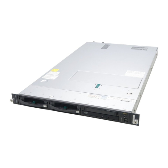
Preface The PRIMERGY RX200 S4 server is an Intel-based server for mid-size networks and large companies. The server is suitable for use as a file server and also as an application, information or Internet server. Overview of the documentation Concept and target groups This Service Supplement completes the information given in the Operating Manual, the Options Guide and the Technical Manual of the system board. - Page 6 Overview of the documentation Preface Information/activity Manual Detailed safety notes “Safety notes and other important information“ manual Features and technical data of the server Operating Manual Installation and operation, among other things: – External ports – Operation – Configuration of the server –...
-
Page 7: Notational Conventions
Notational conventions Information/activity Manual Replacement routines: Service Supplement – Replacing the front panel module – Replacing the chassis ID/temperature sensor – Replacing the fan board – Replacing the SAS board for 3.5-inch drives – Replacing the SAS board for 2.5-inch drives –... -
Page 9: Procedure
Procedure CAUTION! The actions described in these instructions should only be performed by service personnel. Ê First of all please familiarize yourself with the safety instructions in the chapter “Safety notes” on page 11f. Ê Ensure that all required manuals (see Service DVD) are available, printing out the PDF files if necessary. -
Page 11: Safety Notes
Safety notes The following safety notes are also provided in the “Safety notes and other important information” manual. This device complies with the relevant safety regulations for data processing equipment. CAUTION! The actions described in these instructions should only be performed by service personnel. - Page 12 Safety notes CAUTION! This device has a specially approved power cable and must only be connected to a safety socket on the rack mains socket strip. Ensure that the power socket on the device or the grounded wall outlet is freely accessible. The ON/OFF button does not disconnect the device from the mains voltage.
- Page 13 Safety notes CAUTION! Proper operation of the device (in accordance with IEC 60950-1/ EN 60950-1) is only ensured if the casing is completely assembled and the rear covers for the installation openings have been put in place (electric shock, cooling, fire protection, interference suppression).
- Page 14 Safety notes CAUTION! Replace the lithium battery on the system board in accordance with the instructions in the Technical Manual for the system board. All batteries containing pollutants are marked with a symbol (a crossed-out garbage can). In addition, the marking is provided with the chemical symbol of the heavy metal decisive for the classification as a pollutant: Cd Cadmium...
- Page 15 Safety notes Protect the CDs/DVDs from exposure to heat and direct sunlight. Laser information The CD/DVD drive complies with IEC 60825-1 laser class 1. CAUTION! The CD/DVD drive contains a light-emitting diode (LED), which under certain circumstances produces a laser beam stronger than laser class 1.
- Page 16 Safety notes Use a grounding cable designed for this purpose to connect yourself to the system unit as you install components. Place all components on a static-safe base. You will find a detailed description for handling ESD components in the relevant European or international standards (DIN EN 61340-5-1, ANSI/ESD S20.20).
-
Page 17: Replacement Routines
Replacement routines CAUTION! When handling systems and boards, make sure you observe the safety notes in the chapter “Safety notes” on page 11ff. Preparation Ê Exit all applications and shut down the server correctly. Ê If your operating system has not switched off the server, press the On/Off button. - Page 18 Preparation Replacement routines Ê If the pulled-out server is difficult to access in the rack, remove it completely from the rack. If you do not want to remove the server, skip this page. CAUTION! The server has no cable management in the rack! Therefore you must unplug all cables connected to server before you remove it.
-
Page 19: Opening/Closing The Server
Replacement routines Preparation 4.1.2 Opening/closing the server AC T AC T CO MP CO MP Figure 4: Removing the housing cover Ê To take off the housing cover, press the button (1). Ê Slide the cover about 1 cm backward (2) and lift it off. 4.1.3 Removing the air duct Figure 5: Removing the air duct... -
Page 20: Replacing The Front Panel Module
Replacing the front panel module Replacement routines Replacing the front panel module The front panel module consists of the front panel board, an operating panel and a holder. These components are already pre-assembled. Ê Open the server as described in the section “Preparation”... - Page 21 Replacement routines Replacing the front panel module Figure 7: Removing the front panel module Ê Push out the front panel module frontward. Figure 8: Removing the front panel cable Ê Unplug the front panel cable from the front panel module. Ê...
-
Page 22: Replacing The Chassis Id / Temperature Sensor
To enable ServerView and ServerStart to identify the system, the chassis ID prom must be reprogrammed with the ChassisIDProm tool after the new front panel module has been installed. The tool can be downloaded from the Fujitsu Siemens Computers Service and Support page (URL: http://extranet.fujitsu-siemens.com/service/information/intelservers/tools). - Page 23 Replacement routines Replacing the fan board Figure 9: Removing the fan cage Ê Loosen the two screws (see the circles) and remove the fan cage. Figure 10: Removing the fan board Ê Loosen the seven screws (see the circles) and remove the fan board. Ê...
-
Page 24: Replacing The Sas Board For 3.5-Inch Drives
Replacing the SAS board for 3.5-inch drives Replacement routines Ê Reinsert the air duct. Make sure that the hooks of the air duct engage in the fan cage. Ê Close the server and plug in the power plugs (detailed description see the Options Guide). -
Page 25: Replacing The Sas Board For 2.5-Inch Drives
Replacement routines Replacing the SAS board for 2.5-inch drives Replacing the SAS board for 2.5-inch drives Ê Open the server as described in the section “Preparation” on page Ê Pull the four hard disk modules out for a few centimeters. Ê... -
Page 26: Replacing The Power-Distribution Module
Replacing the power-distribution module Replacement routines Replacing the power-distribution module The power-distribution module consists of a power backplane, integrated power supply fans and a housing. In the case of a defect, you must replace the complete module. Ê Open the server as described in the section “Preparation”... -
Page 27: Replacing The System Board
Replacement routines Replacing the system board Ê Connect all cables on the fan board, the SAS board and the system board (see the cabling plan in the Options Guide). Ê Push the power supply unit(s) entirely in place. Ê Close the server and plug in the power plugs (detailed description see the Options Guide). - Page 28 Replacing the system board Replacement routines Figure 14: Position of the screws of the system board Ê Loosen the seven screws of the system board (see the circles). Ê Push the system board about 1 cm in the direction of the housing front. This pulls all the plug connectors out of the external connection panel.
- Page 29 Replacement routines Replacing the system board Ê Reinstall the memory modules in their slots (description see the Options Guide). Ê Reinsert the air duct. Make sure that the hooks of the air duct engage in the fan cage. Ê Close the server and plug in the power plugs (detailed description see the Options Guide).
-
Page 31: Board Layout
Board layout The board layout of the system board is described in the Technical Manual of the system board D2671. Front panel module Part number: A3C40092059 Figure 15: Front panel module Connection Front panel cable Service Supplement RX200 S4... -
Page 32: Sas Boards
SAS boards Board layout SAS boards 5.2.1 SAS board for 3.5-inch drives Part number: SNP: A3C40092046 Figure 16: SAS board for 3.5-inch hard disks Connection C cable Power supply for the SAS board SAS data cable Service Supplement RX200 S4... -
Page 33: Sas Board For 2.5-Inch Drives
Board layout SAS boards 5.2.2 SAS board for 2.5-inch drives Part number: SNP: A3C40092033 Figure 17: SAS board for 2.5-inch hard disks Connection Power supply for the SAS board C cable SAS data cable Service Supplement RX200 S4... -
Page 34: Fan Board
Fan board Board layout Fan board Part number: A3C40092053 Figure 18: Fan board Connection LSP/LSD System fan 1/2 System fan 3/4 System fan 5/6 System fan 7/8 System fan 9/10 System fan 11/12 Auxiliary power supply for the fan board Fan board cable 10 IDE cable for DVD drive Service Supplement... -
Page 35: Power-Distribution Module
Board layout Power-distribution module Power-distribution module Part number: A3C40091728 Figure 19: Power-distribution board Connection Power supply unit 1 Power supply unit 2 Service Supplement RX200 S4... -
Page 37: Index
Index chassis ID ESD (devices sensitive to electrostatic discharge) fan board 22, front panel module 20, laser information light emitting diode (LED) lithium battery meaning of the symbols notational conventions power-distribution module 26, SAS board for 2.5-inch drives 25, SAS board for 3.5-inch drives 24, Service DVD system board target group... - Page 39 Information on this document On April 1, 2009, Fujitsu became the sole owner of Fujitsu Siemens Compu- ters. This new subsidiary of Fujitsu has been renamed Fujitsu Technology So- lutions. This document from the document archive refers to a product version which was released a considerable time ago or which is no longer marketed.