Sony BRS-200 Operational Manual
Hide thumbs
Also See for BRS-200:
- Operating instructions manual (159 pages) ,
- Quick reference manual (8 pages)
Table of Contents
Advertisement
Quick Links
Advertisement
Table of Contents

Related Manuals for Sony BRS-200


Summary of Contents for Sony BRS-200
- Page 1 BRS-200 Operational Manual click: sony.com/sonysports sony.com/ptz...
-
Page 2: Table Of Contents
Table of Contents What is the BRS-200? 1-1) Main features ......................4 1-2) Applications .......................5 Overview 2-1) Control panel ......................6 2-2) Rear panel of the processor unit ................8 Main Features 3-1) Compact system .....................10 3-2) Remote camera control capability ................10 3-3) Switcher mode and camera control mode ............11... - Page 3 Operating the camera menu .................61 9-9) Controlling the tally lamp ..................61 Operation Using External Device 10-1) Transferring data between the BRS-200 and computer ........62 10-2) Specifications for a GPI I/O connector ..............67 10-3) Using the REMOTE Connector .................68 Technical Appendix 11-1) Menu list ........................69...
-
Page 4: What Is The Brs-200
What is the BRS-200? The BRS-200 is an all-in-one live production and presentation switcher with BRC Series control functionality. With this powerful tool, you can achieve a one-man production operation in either HD or SD system configuration. 1-1) Main features... -
Page 5: 1-2) Applications
What is the BRS-200? 1-2) Applications Auditorium/Concert Hall City Council Corporate/Boardroom Education House of Worship Weddings/Events Sports Event Studio... -
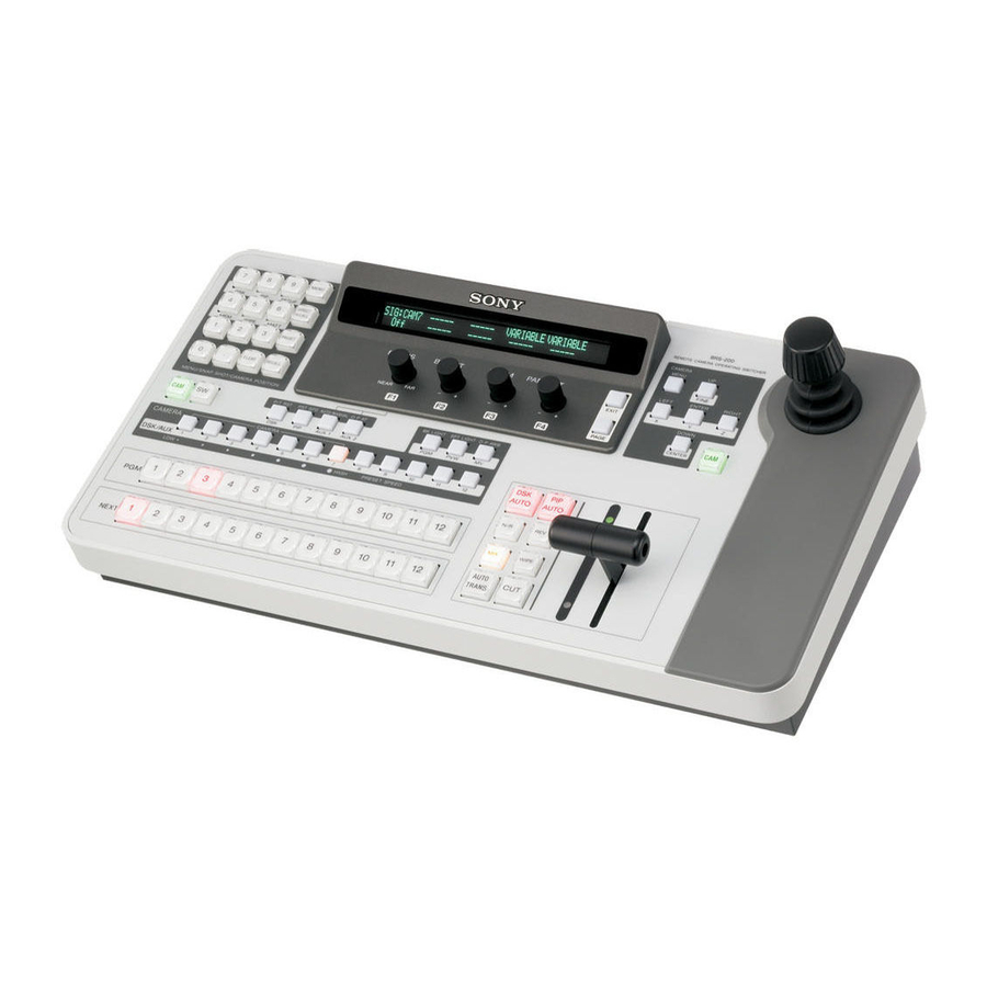
Page 6: Overview
Overview 2-1) Control panel... - Page 7 Overview 1. Mode button 2. CAMERA/DSK/AUX bus section (Camera mode/Switcher Backlight button / One Push AF button / PGM button AUX 2 button mode select) AUTO/MANUAL button / SPT LIGHT button / AUX 1 button PVW button Preset Speed button / One Push PIP button AWB button /...
-
Page 8: 2-2) Rear Panel Of The Processor Unit
Overview 2-2) Rear panel of the processor unit... - Page 9 Overview GPI I/O PANEL PGM1 PGM2 AUX1 AUX2 SDI IN SDI OUT SDI I 1 to 4 connectors PGM1/PGM2 output connectors AUX1/AUX2 output connectors GPI I/O connector PA EL connector (ground) terminal DVI-I OUT connector ~ AC I connector AC IN DVI-I OUT RS-232C LAN(10/100)
-
Page 10: Main Features
Main Features 3-1) Compact system 1 unit 2 units (BRS-200) 3-2) Remote camera control capability control unit BRC-H700 BRC-Z700 BRC-Z330 BRC-300... -
Page 11: 3-3) Switcher Mode And Camera Control Mode
Main Features 3-3) Switcher mode and camera control mode CAM mode: Position presets, Recall CAM mode: Camera menu selection SW mode: Snapshot presets, Recall SW mode: P in P position selection CAM mode: Camera selection CAM mode: PTZ control SW mode: DSK/AUX bus selection SW mode: P in P position/Size selection PGM/ EXT bus control Note: PGM/NEXT bus control can be operated both in CAM mode and SW mode. -
Page 12: 3-4) Rich Selection Of Inputs And Outputs
Main Features 3-4) Rich selection of inputs and outputs AC IN DVI-I OUT IN 1 card slot OUT card slot IN 2 card slot RS-232C GPI I/O PANEL LAN(10/100) REMOTE PGM1 PGM2 AUX1 AUX2 REF IN REF OUT RS-422 SDI IN SDI OUT GENLOCK VISCA... -
Page 13: 3-5) Equipped With Dvi Output As Standard
Main Features 3-5) Equipped with DVI output as standard and XGA in SD mode operators to view footage on a cost-effective HDTV monitor or PC monitor with an analog component terminal DVI-I Connection WUXGA, SXGA, WXGA, XGA mode DVI I PC Monitor RGB I D-Sub... -
Page 14: 3-6) Multi-Viewing Function
Main Features 3-6) Multi-viewing function DVI-I outputs Picture number Type of multi-viewer Factory preset output video TYPE1 TYPE4 IN 1 IN 2 TYPE10 IN 1 IN 2 IN 3 IN 4 IN 5 IN 6 IN 7 IN 8 TYPE16 FM 1 FM 2 IN 1... -
Page 15: Specifications
RS-422: D-sub 9-pin (×1) (for switcher control from external devices) Signals VISCA camera VISCA RS-232C: Mini DIN 8-pin (×1) control VISCA RS-422: 5-pin contact connector (×1) (for BRC Series camera control) preset positions) *1: The BRS-200 does not accept the mix of HD-SDI and SD-SDI. to the BRS-200.) -
Page 16: System Examples
System Examples 5-1) Basic configuration HD-SDI Card (MV) HD-SDI VISCA HD-SDI HD-SDI (PGM) HD-SDI Card 5-2) For live production HD-SDI SDI Adaptor (PGM) HD-SDI Card (MV) HD-SDI VISCA HD-SDI SDI Adaptor (AUX1: PRV) HD-SDI HD-SDI Card HD-SDI (PGM) -
Page 17: For Presentation
System Examples 5-3) For presentation HD-SDI Card HD-SDI BRSA-20DD2 (PGM) VISCA HD-SDI HD-SDI Card (MV) Composite BRSA-20SA1 or S-Video (1) RGB –– > DVI HD-SDI BRSA-20DD1 (PGM) * SD analog source can be input in conjunction with HD-SDI source by using BRSA-20SA1. 5-4) For presentation with dual projectors HD-SDI Card... -
Page 18: Basic Setup And Operation
Basic Setup and Operation This section explains how to perform basic system setup. Basic component of system configuration 6-1) Turning on the power 1. Set the power switch on the front of the processor unit to ON. 2. Set the power switch at the rear of the control panel to ON. 3. - Page 19 Basic Setup and Operation System connection BRC-series cameras Monitor equipped Monitor equipped with the HD-SDI with HD-SDI input with DVI input output card attached HD-SDI IN DVI IN - 4 2 - 2 3 SDI OUTPUT Power cord stopper RS-232C to AUX1 to DVI-I OUT Processor Unit...
-
Page 20: 6-2) Menu Operation
Basic Setup and Operation 6-2) Menu operation MENU SETUP DIRECT RECALL WIPE MATT PRESET CLEAR RECALL MENU/SNAP SHOT/CAMERA POSITION umeric buttons, . (dot) button ME U button Every menu consists of three digit number. Please see technical appendix 11-1. A 3 -digit menu page is assigned to each of all the setting menus displayed in menu mode. - Page 21 Basic Setup and Operation SETUP CAMERA INPUT OUTPUT PANEL Display panel SYSTEM UTILITY STATUS REBOOT FOCUS BRIGHT ZOOM PAN/TILT EXIT NEAR PAGE Adjustment controls are used to set the items displayed above each control. Higher menu layer Lower menu layer Page number lower menu layer.
-
Page 22: 6-3) Setting The System Format
Basic Setup and Operation 6-3) Setting the system format MENU 1. Press SYSTEM FORMAT FRAME ASPECT APPLY SYS MODE 59.94 16:9 Exec 2. Set the video signal format, frame frequency and aspect ratio. (FORMAT) : Select HD or SD (FRAME) : Select 59.94 or 50 (ASPECT) : Select 16:9 or 4:3... -
Page 23: 6-4) Setting Up Video Signal For Monitor Output
Basic Setup and Operation 6-4) Setting up video signal for monitor output This section explains how to use a four-picture multi-viewer so that images from two cameras can be viewed on one monitor. 1. Press [SW] [AUX 1] [MV] in this sequence. Each button will light up when pressed. -
Page 24: 6-5) Setting Up The Visca Camera
Basic Setup and Operation 6-5) Setting up the VISCA camera This section explains how to set the VISCA communication mode according to the premised system configuration. Check that the following settings have been made on the camera. MENU 1. Press CAMERA CONTROL BAUD... -
Page 25: Preparation
DVI-I IN SDI IN GPI I/O PANEL PGM1 PGM2 AUX1 AUX2 SDI IN SDI OUT Video signals built-in the BRS-200 I 1 to I 4 I 5 to I 8 Color Bars Matt 1 Frame memory 1 MENU INPUT XPT BTN... - Page 26 Preparation I 1 to I 9 MENU Frame Sets Frame Synchronizer O /OFF synchronizer MENU Color Bars Matt 1 Frame NAME memory 1 Sets the name of each input (4 characters) Selectable characters (Space) ! “ # $ % & ‘ ( ) * + , – . / 0 1 2 3 4 5 6 7 8 9 : ;...
-
Page 27: 7-2) Setting Up Video Output Signal
Preparation 7-2) Setting up video output signal DVI output DVI-I OUT DVI-I OUT GPI I/O PANEL LAN(10/100) REMOTE PGM1 PGM2 AUX1 AUX2 REF IN REF OUT SDI OUT GENLOCK AUX output MENU Press OUTPUT BOARD BUSSEL RESO (BUSSEL) (RESO) Select the DVI output resolution: (*) HDCP is not supported. - Page 28 Preparation 1. Press 2. Press to light up the [AUX1] or [AUX2] button. 3. Press to light up any one of these buttons to select output. Cross-point 1 to 12, PGM, PVW, MV. NEAR CLEAR RECALL MENU/SNAP SHOT/CAMERA POSITION P/T RST PST SPD AUTO/MANUAL O P AF...
-
Page 29: Switcher Operation
Switcher Operation This section explains how to execute the BRS-200’s switcher functions. 8-1) Outline Picture-in-Picture (PIP). Background video Foreground video This illustration shows the structure of the images to be switched or composed by video switching. PIP video Program video... - Page 30 An orange mark is displayed for NEXT. Press the NEXT select button to which the next output video is assigned. A block diagram of the main part of the BRS-200 is shown below. Input 1 to 4 Key Source Input 5 to 8...
-
Page 31: Cut/Mix
Switcher Operation 8-2) Cut/Mix Example of a Cut: AUTO AUTO WIPE AUTO TRANS 1. Press CUT buttun. 1. Press the Mix button. AUTO AUTO WIPE AUTO TRANS 2. Press the AUTO 2. Move the TRAN button. transition lever. Example of a Wipe: 1. -
Page 32: 8-3) Wipe
Switcher Operation 8-3) Wipe 1. Select the Wipe pattern (shown below). 2. Press the [WIPE] button. AUTO AUTO WIPE AUTO TRANS 3. Press the [AUTO 3. Move the TRAN] button. transition lever. Example of a wipe pattern 1. Press 2. Turn to select the wipe pattern. - Page 33 Switcher Operation You can store and recall ten Wipe patterns using numeric buttons. 1. Press 2. Turn to select the Wipe pattern to be stored. SW MODE MV TYPE XPT HOLD ME AUTO SNAP: NEAR 3. Press to select “DIRECT.” SW MODE MV TYPE XPT HOLD...
- Page 34 Switcher Operation MENU 1. Press WIPE WIDTH BORDER NEAR 2. Turn to set the color and width of the border. (SAT) : 0.0 to 100.0 (HUE) : 0.0 to 359.5 Boarder T I P S (1) For a rapid dial while pressing. (2) The joystick can be used to change the color of a border.
- Page 35 Switcher Operation this function is canceled. ormal transition When the [REV] button is pressed then goes dark. When you press the [N/R] button The first transition The second transition...
-
Page 36: 8-4) Picture-In-Picture (Pip)
Switcher Operation 8-4) Picture-in-Picture (PIP) You can compose videos using the PIP function by embedding a video within another video. Embedded video 3. Press one of the “SDK/AUX” 1 to 1. Press 2. Press [PIP]. 12 to select a video to embed. BK LIGHT SPT LIGHT O P AWB... - Page 37 You can set the size and display position of a video to be embedded in Picture-in-Picture (PIP). Default setting Adjustment example 1 Adjustment example 2 Using the joystick: BRS-200 REMOTE CAMERA OPERATING SWITCHER CAMERA MENU Joystick FINE FI E button...
- Page 38 Switcher Operation You can store and recall 10 settings of the PIP using numeric buttons. 1. Set up the value of PIP (SIZE, H POS, V POS) by using [MENU810] and [MENU820]. SIZE DRCT NO. PRESET MENU 2. Press SIZE None Exec 3.
- Page 39 Switcher Operation You can crop an unwanted portion of a video and embed it in PIP. Cropping MENU 1. Press CROP 2. Turn to set “CROP” to “On.” 3. Press Menu page 841 is displayed. LEFT RIGHT BOTTOM CROPPOS –12.0 12.0 –9.0 4.
- Page 40 Switcher Operation You can set the executing time for a transition using PIP AUTO. 1. Press 2. Press to select “PIP AUTO.” SW MODE MV TYPE XPT HOLD PIP AUTO SNAP: NEAR 3. Turn to set the time (0 to 999 frames). You can check and adjust the results of PIP (picture-in-picture) in the preview window before displaying this as program output video.
-
Page 41: 8-5) Dsk
Switcher Operation 8-5) You can add characters or graphics to a video that includes any effect or composition. The Downstream Key (DSK) is useful for superimposing characters. Background video Program video LESSON 1 LESSON 1 DSK FILL video Foreground video There are three types of keys: a key signal (DSK SOURCE) created by a specific brightness of the DSK (DSK SOURCE) created by a specific brightness of the DSK SOURCE video... - Page 42 Switcher Operation BRS-200 SETUP MENU FINE WIPE MATT LEFT ENTER RIGHT FOCUS BRIGHT ZOOM PAN/TILT EXIT DOWN NEAR PAGE MENU/SNAP SHOT/CAMERA POSITION P/T RST PST SPD O P AF BK LIGHT SPT LIGHT O P AWB AUX 1 AUX 2...
- Page 43 Switcher Operation 8-5-1) Luminance Key A video is created by detecting the differences of the components of Luminance key Background video DSK FILL video composition LESSON 1 LESSON 1 Black background 1. Press P/T RST PST SPD AUTO/MANUAL O P AF 2.
- Page 44 Switcher Operation 8-5-2) Chroma Key A video is created by detecting a specific color component (chroma) to cut a portion from the Background video DSK FILL video Chroma key composition Blue background 1. Press P/T RST PST SPD AUTO/MANUAL O P AF 2.
- Page 45 Switcher Operation 1. Press 2. Press to light up the DSK button. P/T RST PST SPD AUTO/MANUAL O P AF AUX 1 AUX 2 3. Select a DSK FILL video with one of the DSK/AUX 1 to 12 buttons. CAMERA CAMERA DSK/AUX MENU...
- Page 46 Switcher Operation 8-5-3) DSK split To compose video using the DSK split DSK FILL video The DSK split function enables assignment Background video DSK split composition of a specific DSK SOURCE video that determines the composing area of a LESSON 1 DSK SOURCE video PANEL XPT BTN...
- Page 47 Switcher Operation MENU 1. Press FILL 2. Turn , and to adjust the LUM (luminance), SAT (saturation), and HUE of the monochromatic image. 3. Turn to set FILL to “On.” When the DSK transition is executed, the adjusted monochromatic image is composed as a DSK FILL video. You can check and adjust the results of DSK in the preview window before displaying this as program output video.
-
Page 48: 8-6) Internal Sources
Switcher Operation 8-6) Internal Sources 8-6-1) To Use Color Bars or Color Mattes mattes as a background. MENU 1. Press and set “CLBR” (color bar), “MAT1” (color matte 1), or “MAT2” (color matte 2) under “SIGNAL.” INPUT XPT BTN SIGNAL NAME INHIBIT ASSIGN... - Page 49 Switcher Operation 8-6-2) Using Still Images Stored in Frame Memory source. The BRS-200 has two frame memories: FM 1 and FM 2. MENU 1. Press SIGNAL DIST FREEZE IN 1 FM 1 Exec 2. Turn to select the input signal from IN1 to IN9, FM1/FM2, MAT1/ MAT2, CLBR, PGM, and PVW.
-
Page 50: 8-7) Storing Settings
Switcher Operation 8-7) Storing Settings menu items in the switcher registers. There are three registering functions: Function Setting items to be Register numbers Maximum registered number of registers Snapshot Setting data on setting Snapshot numbers 0 menu pages 400 to 850 to 99 Direct wipe Wipe pattern... - Page 51 Switcher Operation 1. Press 2. Press to display “DIRECT”. 3. Turn to select SS, Wipe, or PIP under DIRECT. DIRECT 4. Check that the is not lit. RECALL 5. Press one of the numeric buttons 0 to 9 to enter the register number in which the setting you wish to recall is stored.
-
Page 52: Visca Camera Operation
VISCA Camera Operation This section explains how to remotely control BRC Series cameras from the BRS-200. 9-1) Functions The following RM-BR300 functions are supported by the BRS-200. RM-BR300 BRS-200 BRS-200 MENU REMOTE CAMERA OPERATING SWITCHER CAMERA SETUP MENU FINE WIPE... -
Page 53: 9-2) Setting Up Brc Series Camera Connection
VISCA Camera Operation 9-2) Setting up BRC Series camera connection This section explains how to connect BRC Series cameras with the BRS-200. CAMERA CONTROL BAUD MODEL APPLY MENU VISCA RS-232C 9600 Auto Exec 1. Press and set the VISCA setting. -
Page 54: 9-3) Operating Pan/Tilt/Zoom
VISCA Camera Operation 9-3) Operating pan/tilt/zoom Press operated. Upward Zoom Zoom Right Left (Wide) (Telephoto) Joystick Downward Two modes are available for pan/tilt/zoom speed. CONSTANT Constant speed regardless of the angle of joystick inclination or turning Increasing speed according to the angle of joystick inclination or turning 1. -
Page 55: 9-4) Adjusting The Focus
VISCA Camera Operation 9-4) Adjusting the focus There are two Focus Control modes: Auto focus and Manual focus. Auto focus mode AF assist function is available (for BRC-Z700/Z330). Focus mode Manual focus mode One-push AF is available. Turn to adjust the manual focus and AF assist. Press FOCUS to focus on a near subject... -
Page 56: 9-5) Adjusting The Exposure
VISCA Camera Operation 9-5) Adjusting the exposure Press The exposure setting value is shown on the display panel above (BRIGHT) according to the camera’s exposure setting. SIG: CAM1 FOCUS SPEED CONSTANT CONSTANT POS: AUTO 1/1000 15/24 FOCUS BRIGHT ZOOM PAN/TILT NEAR Exposure mode Indication on the panel... -
Page 57: 9-6) Selecting One-Push Auto White Balance
VISCA Camera Operation 9-6) Selecting One-push Auto White Balance 1. Press 2. Press the [OP AWB] button. One-push AWB button BK LIGHT SPT LIGHT O P AWB... -
Page 58: Using The Camera Position Preset
VISCA Camera Operation 9-7) Using the camera position preset MENU SETUP DIRECT DIRECT RECALL button RECALL WIPE MATT umeric buttons PRESET button PRESET RECALL button CLEAR RECALL MENU/SNAP SHOT/CAMERA POSITION CLEAR button 1. Press the [CAM] button and one of the CAMERA 1 to 7 buttons to select the camera. - Page 59 VISCA Camera Operation 1. Press the [CAM] button and one of the CAMERA 1 to 7 buttons to select the camera. CAMERA CAMERA DSK/AUX 2. Check that the [DIRECT RECALL] button is not lit. 3. Enter the camera position number (1 to 99) to be recalled by pressing the numeric buttons 0 to 9.
- Page 60 VISCA Camera Operation You can adjust the pan/tilt speed at which the camera moves to a preset position. P/T RST PST SPD AUTO/MANUAL O P AF AUX 1 AUX 2 CAMERA CAMERA DSK/AUX 1. Follow the steps in “To recall preset camera settings” to recall the camera setting.
-
Page 61: 9-8) Operating The Camera Menu
VISCA Camera Operation 9-8) Operating the camera menu The on-screen menu of the BRC Series can be operated by the BRS-200. 1. Press the [CAM] button and one of the CAMERA 1 to 7 buttons to select the camera. CAMERA... -
Page 62: Operation Using External Device
Operation Using External Device 10-1) Transferring data between the BRS-200 and computer This section explains how to connect and transfer data between the BRS-200 and a computer. connector on a computer. DVI-I IN AC IN DVI-I OUT SDI IN RS-232C... - Page 63 Operation Using External Device Access the Internet without using a proxy server. 1. Right click the icon on the task bar to open up the network connection. The right window opens up. 2. Select the local area connection and right click to open property. In the subsequent window, select Internet protocol (TCP/IP).
- Page 64 (IP address of the switcher)/ 2. Enter the user name (brs200) and password (sony) in the logon window, then click Logon. The computer is connected to FTP server in the BRS-200. The window for storing data set in step 1 will open.
- Page 65 Operation Using External Device the image data stored in the BRS-200 to the computer’s destination folder. the image data stored on the computer to the FTP server in the BRS-200. T I P S data automatically. MENU 1. Press LOAD...
- Page 66 BRS-200. The uploaded setting data from the computer are enabled after the upload is completed and the Processor Unit and Control Unit are turned off then rebooted. Note: When transferring image data between the BRS-200 and a computer with the BRS-200’s Computer BRS-200 Creating an image file for...
-
Page 67: 10-2) Specifications For A Gpi I/O Connector
(FUNCTION) : select the functions you wish to assign to pin numbers 1 to 12 (please refer to the functions explained in technical appendix 11-3) selected) (I/O DIR) : Output/Input (selecting Output enables an external Input means you can operate the BRS-200 from an external device) -
Page 68: 10-3) Using The Remote Connector
Operation Using External Device 10-3) Using the REMOTE Connector This section explains how to control the switcher by a computer via the remote connector on the switcher. Communication method LAN(10/100) REMOTE D-sub 9-pin RS-422A compatible Synchronous system: asynchronous Character length: 8 bits Stop bit: 1 bit (MARK) START... -
Page 69: Technical Appendix
Technical Appendix 11-1) Menu list This section shows the menu list that is consist of the camera mode menus menus in menu mode. The three-digit number shown in the setting menu and submenu (setting item) of the menu list below is the menu page number assigned to each menu. - Page 70 Technical Appendix Switcher Mode Menu Adjustment Indication/ Description control Setting item SW MODE (Switcher mode indication) – SNAP: 0 to 99 (snapshot number The number of mode selected under DIRECT above the F3 control indication) is displayed. WIPE: 0 to 9 (direct wipe number indication) PIP: 0 to 9 (direct PIP number...
- Page 71 Technical Appendix WIPE Menu Setting menu Setting item Description 500 PATTERN.. 510 NUMBER 000, 001, 002, 003, 004, 005, 021, Turn the F1 or F2 control to select a wipe pattern. 022, 023, 028, 029, 031, 040, 051, Storing it in the direct wipe number is supported. 057, 058, 074, 082, 096, 098 For details, see “To store a wipe pattern in the (Figure)
- Page 72 Technical Appendix DSK Menu Setting menu Setting item Description 700 KEYMODE.. 710 TYPE Lum, Split, Chroma You can select the DSK type from among Lum (luminance key), Split, and Chroma (chroma key). FILL (4-character indication) The DSK FILL signal selected with the DSK button and SOURCE (4-character indication) DSK/AUX 1 to 12 buttons is displayed under FILL.
- Page 73 Technical Appendix PIP Menu Setting menu Setting item Description Use the F1 control or the dial on the upper part of the joystick to set the size of an embedded video for PIP: DRCT NO. None, 0 to 9 Storing it in the direct PIP number is supported.
- Page 74 Technical Appendix SETUP Menu Note: If you changed the values of the setting items in the SETUP menu (menu pages 900s) and items. Press the PAGE button (yes) to reboot the switcher or to store the changed settings. The stored settings are retained in memory when the switcher is turned off and on again. When the Setting menu Setting item Description...
- Page 75 The F1 to F3 controls and the joystick can 0.0 to 359.5 (in 0.5) be used for the setting. MENU built in the BRS-200 can be named in four characters to register. MENU 1. Press 2. Turn to select the signal to be named.
- Page 76 Technical Appendix Setting menu Setting item Description 900 OUTPUT.. 930 AUX.. 931 BUS AUX1, AUX2 Selects the function and specification of the AUX1 and AUX2 output connectors. ANCIL Off, On Allows output of ancillary data superimposed Off, On on an SDI signal without masking when ENBL ANCIL is set to On.
- Page 77 Technical Appendix Setting menu Setting item Description 900 PANEL.. 940 DSKBUS.. 941 XPT BTN 1 automatically to the DSK FILL signal selected FILL (4-character indication) with the DSK/AUX select button 1 to 12. SIGNAL IN 1, IN 2, IN 3, IN 4, IN 5, IN 6, IN 7, IN 8, IN 9, FM 1, FM 2, MAT1, MAT2, CLBR SOURCE (4-character indication)
- Page 78 Technical Appendix Setting menu Setting item Description 900 SYSTEM.. 950 SYSMODE.. 951 FORMAT SD, HD Selects the system that the switcher supports. FRAME 59.94, 50 ASPECT 4:3, 16:9 Note When FORMAT is set to HD and ASPECT is APPLY Exec set to 4:3 on menu page 951, a PGM or PVM output image will remain in the portions outside the 4:3 display.
- Page 79 Technical Appendix Setting menu Setting item Description 900 UTILITY.. 960 REMOTE.. 962 CONTROL Off, On Sets up the REMOTE connector. BAUD 9600, 19200, 38400 PARITY None, Even, Odd APPLY Exec LAN.. 963 IPADD 1.1 to 255.255 Sets up the IP address and network mask of the switcher for communication with a NET MASK 0.0 to 255.255 (255.0) computer.
-
Page 80: 11-2) Wipe Pattern
Technical Appendix 11-2) WIPE pattern the pattern numbers are as follows: The arrows in the wipe patterns indicate the direction of a transition. -
Page 81: 11-3) Gpi I/O
50 mA at 50 mA at maximum maximum less than 0.5 V Processor Unit of the Processor Unit of the BRS-200 External device BRS-200 External device external lamp is connected Maximum voltage: 40 V Maximum current:... -
Page 82: 11-4) Remote Connector
Technical Appendix 11-4) REMOTE connector Command list controllable with external devices Return command sent to an external device Function Protocol by the switcher CROSS 03 01 80 XX 01: Button 1 POINT n: Button n Function Protocol NEXT 03 01 81 XX 01: Button 1 n: Button n 84 (hexadecimal) -
Page 83: 11-5) Visca Connector
Technical Appendix 11-5) VISCA Connector VISCA RS-422 connector VISCA RS-232C output connector (connector plug, 5-pin) (mini DIN 8-pin, female) RS-232C RS-422 1 2 3 4 5 VISCA VISCA Pin No. Function Pin No. Function Pin No. Function Pin No. Function OUT–... -
Page 84: 11-7) Conversion Between Input Signal And Output Signal
Technical Appendix 11-7) Conversion between input signal and output signal appears when output from SDI output connector and DVI-I output connector on the switcher. Note: SDI input signal SYSTEM Input Output mode DVI OUT FORMAT SDI IN SDI OUT ASPECT 1024 ×... - Page 85 Technical Appendix SYSTEM Input Output mode DVI OUT FORMAT DVI IN SDI OUT ASPECT 1024 × 768 1280 × 768 1280 × 1024 1920 × 1080i 1920 × 1200 Zoom Center Wide Zoom *Black bands on both sides of the image are increased on DVI OUT images for DVI (5:4) signals. SYSTEM Input Output...
-
Page 86: 11-8) Acceptable Dvi-I Input/Output Signal Format
Technical Appendix 11-8) Acceptable DVI-I Input/Output Signal format DVI-I input signal formats Dot clock H sync V sync Digital Analog Resolution Signal format fH (kHz) fV (Hz) (MHz) polarity polarity input input 1024 × 768 VESA (DMT) 48.363 60.004 H-neg V-neg Supported Supported XGA 60 Hz... -
Page 87: 11-9) Camera Settings That Can Be Recalled With The Position Numbers Of The Switcher
Technical Appendix 11-9) Camera Settings that Can Be Recalled with the Position Numbers of the Switcher When the camera settings are preset for position numbers 17 to 99 (7 to 99 for to the camera after recalling are as follows: Camera Setting items BRC-300/300P... -
Page 88: 11-10) Messages And Troubleshooting
Technical Appendix 11-10) Messages and Troubleshooting This section explains a message that may appear on the display panel. Check this section before consulting your Sony Authorized Reseller. If the switcher consult your Sony Authorized Reseller. Number Message Description Solution 1001 Booting Now. -
Page 89: 11-11) Dimensions
Technical Appendix 11-11) Dimensions Control Panel... - Page 90 Technical Appendix Processor Unit 17 (430) × (6.2 × 12) (4 holes) POWER (462) 19 (480) Unit: inches (mm)
- Page 91 ©2010 Sony Electronics Inc. All rights reserved. Reproduction in whole or in part without written permission is prohibited. Non metric weights and measurements are approximate. Windows and Internet Explorer are trademarks of Microsoft Corporation. All other trademarks are the properties of their respective owners.