Table of Contents
Advertisement
Advertisement
Table of Contents

Related Manuals for Panasonic AFP0HC32ET


Summary of Contents for Panasonic AFP0HC32ET
- Page 2 ● Do not undertake construction (such as connection and disconnection) while the power supply is on. It could lead to an electric shock. ● If the equipment is used in a manner not specified by the Panasonic, the protection provided by the equipment may be impaired.
- Page 3 Introduction Thank you for buying a Panasonic product. Before you use the product, please carefully read the installation instructions and the users manual, and understand their contents in detail to use the product properly. Types of Manual • This manual describes the "EtherNet/IP communication function" implemented in FP0H Control Unit.
- Page 4 Glossary Glossary The following terms are used in this manual and the EtherNet/IP setting tool. Term Description The side which opens the connection of the cyclic communication is called Originator originator, i.e. controllers such as PLC. Target The side which the connection is opened is called target, such as PLC, I/O devices. Connection setting with targets registered in FP0H.
- Page 5 Glossary Term Description For connecting from an originator to target, there are two methods to specify the device area of the target. - by specifying numbers (Instance) Communication Method - by specifying symbols (Tag). (Tag/Instance) When setting connections, the methods available for each target are displayed. For using the FP0H as a target, either method can be selected.
- Page 6 Glossary Term Description The packet whose size is within 510 bytes is called normal packet. The packet whose size is 511 bytes to 1444 bytes is called larget packet. The maximum communication performance varies according to the data size used for Normal packet and communication.
-
Page 7: Table Of Contents
Table of Contents Table of Contents 1. FP0H EtherNet/IP Function ..........1-1 What is EtherNet/IP?................1-2 1.1.1 Overview of EtherNet/IP ................1-2 1.1.2 FP0H EtherNet/IP Function ..............1-2 Names and Functions of Parts .............. 1-4 1.2.1 Control Unit ..................... 1-4 1.2.2 LED Displays When PLC Operates ............ - Page 8 Table of Contents Initial Setting of Ethernet /IP ..............3-4 3.2.1 Ethernet Settings ..................3-4 3.2.2 Starting EtherNet/IP Setting Screen ............3-5 3.2.3 EtherNet/IP Basic Configuration ............. 3-6 3.2.4 Items of Ethernet /IP Basic Configuration ..........3-7 Settings of Connection Using FP0H as Originator ......... 3-8 3.3.1 Settings....................
- Page 9 Table of Contents Device List Window ................4-7 4.2.1 Display Contents of Device List Window..........4-7 4.2.2 Operations from EDS File Menu ............. 4-8 Various Setting Screens ................ 4-9 4.3.1 Operations in Device Setting Screen ............4-9 4.3.2 Operations in Connection Setting Screen ..........4-10 4.3.3 Operations in I/O Map Setting Screen ..........
- Page 10 Table of Contents 7. Reference Information ............7-1 Calculation Method of Load Factor ............7-2 Cyclic Communication: List of Abnormal Statuses ......... 7-5 PLC Link and Ethernet Switch ............... 7-7 8. Appendix ................8-1 Supported Data Types ................8-2 viii...
-
Page 11: Fp0H Ethernet/Ip Function
FP0H EtherNet/IP Function... -
Page 12: What Is Ethernet/Ip
FP0H EtherNet/IP Function 1.1 What is EtherNet/IP? 1.1.1 Overview of EtherNet/IP EtherNet/IP (Ethernet Industrial Protocol) is an industrial multi-vendor realtime Ethernet system for executing the communication protocol for CIP (Common Industrial Protocol) control in an application layer on standard Ethernet. Cyclic communication can be performed among devices compatible with EtherNet/IP. - Page 13 1.1 What is EtherNet/IP? For the communication between the FP0H and other I/O devices, the FP0H is the originator. According to devices, the data transmissions by "Input Only" (from target to originator) and "Exclusive Owner" (two-way) may be available. Connection FP0H I/O device Input Only...
-
Page 14: Names And Functions Of Parts
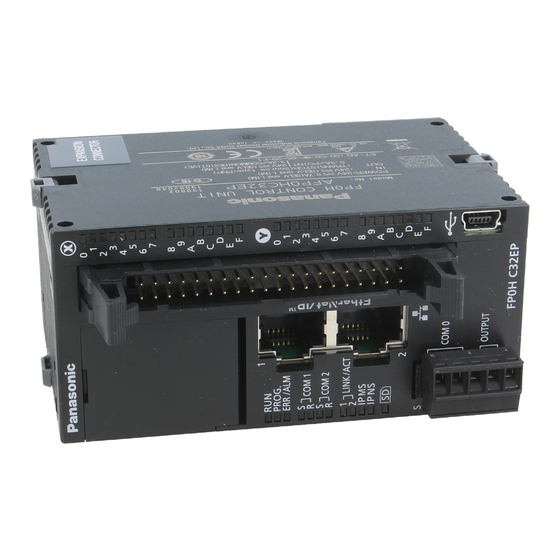
FP0H EtherNet/IP Function 1.2 Names and Functions of Parts 1.2.1 Control Unit ① ② Names and Functions of Parts Number Name Description It is mounted to the FP0H Control Unit (Ethernet type). It is used for connecting to Ethernet and EtherNet/IP. ①... -
Page 15: Led Displays When Plc Operates
1.2 Names and Functions of Parts 1.2.2 LED Displays When PLC Operates The state of the PLC can be confirmed from the lighting state of the LEDs when the PLC is operating. The PLC states indicated by the LEDs are as follows. MS (Module status indicator) <Green/Red>... - Page 16 FP0H EtherNet/IP Function LED displays when PLC is started The MS and NS LEDs turn on in the following order when the FP0H is started. Each lighting time of the lighting order 1 to 4 is 0.25 seconds. Lighting state Lighting order Green ON Red ON...
-
Page 17: Restrictions
1.3 Restrictions 1.3 Restrictions Connecting to External Devices LAN ports 1 and 2 have the same IP address and MAC address. • Do not connect the cables from the two LAN ports to the same switching HUB. • When performing dasiy chain connection, do not connect devices in a ring shape. ... - Page 18 FP0H EtherNet/IP Function...
-
Page 19: Cyclic Communication
Cyclic Communication... -
Page 20: Cyclic Communication Function
Cyclic Communication 2.1 Cyclic Communication Function 2.1.1 Overview of Cyclic Communication The cyclic communication is a function to perform data transmission with constant intervals (RPI) between PLC and PLC or PLC and I/O device on the EtherNet/IP network. In the cyclic communication, one device opens a communication line which is called connection for a destination device. -
Page 21: Operation Of Cyclic Communication
2.1 Cyclic Communication Function 2.1.2 Operation of Cyclic Communication The communication behavior in the cyclic communication varies according to the settings of connections. Description Input Only Data is sent in the input direction only (From target to originator) Exclusive Owner Data is sent bi-directionally. -
Page 22: Data Refresh Of Cyclic Communication
Cyclic Communication 2.1.3 Data Refresh of Cyclic Communication In the cyclic communication, data is refreshed in synchronization with operation cycle and RPI. The refresh of sent data and received data is controlled for each RPI. <Receiver side> <Sender side> Input Output refresh refresh... -
Page 23: Data Area Specifications Using Tag/Instance
2.1 Cyclic Communication Function 2.1.4 Data Area Specifications Using Tag/Instance In the cyclic communication, the data send and received areas are specified using "Tag" or "Instance". • For "Tag", the areas are specified by symbols. For "Instance", they are specified by numbers. -
Page 24: Cyclic Communication Of Fp0H
Cyclic Communication 2.2 Cyclic Communication of FP0H 2.2.1 Connection using FP0H as originator FP0H Originator Connection 2 Sending/Receiving data Connection 1 Receiving data Low-order PLC I/O device Input Only Exclusive Owner Target 1 Target 2 Register target low-order PLCs and I/O devices in "Scan List" of FP0H and register connection information. -
Page 25: Connection Using Fp0H As Target
Use Programming software FPWIN GR7 for the registration. The EDS file of FP0H can be downloaded from our website. • https://industrial.panasonic.com/ac/e/dl_center/software/ For using the FP0H as a target, the both methods, tag and instance, are • available. However, the selectable instance IDs for the instance method are... -
Page 26: Example Of Configuration When Fp0H Is Originator And Target
Cyclic Communication 2.2.3 Example of Configuration When FP0H is Originator and Target Example of Configuration When FP0H is Originator and Target Originator 1 Target 1 Connection 1 Connection 2 Sends data to FP7. Sends data from FP7. FP0H FP0H Connection 3 Connection 4 Connection 5 Receives data. -
Page 27: Setting Procedure
Setting Procedure... -
Page 28: Overview Of Settings
Setting Procedure 3.1 Overview of Settings 3.1.1 System Example This chapter describes the case of setting FP0H(A) in the following system example. Tag_Test1 LD30 LD39 IP:192.168.1.5 Originator Target Tag_Test1 LD30 FP0H(A) LD39 Tag_Test2 LD40 IP:192.168.1.6 LD49 Originator Target Tag_Test2 LD40 FP0H(B)... -
Page 29: Setting Procedure
3.1 Overview of Settings 3.1.2 Setting Procedure The setting procedure is as follows. Use Programming software Control FPWIN GR7 (hereinafter referred to FPWIN GR7) for the settings. Item Outline of operation Reference Enable EtherNet/IP communication in the "Ethernet settings" Initial setting of Ethernet /IP p.3-4 and make the initial setting of EtherNet/IP. -
Page 30: Initial Setting Of Ethernet /Ip
Setting Procedure 3.2 Initial Setting of Ethernet /IP 3.2.1 Ethernet Settings This is the setting for the communication function via LAN ports including EtherNet/IP. Use FPWIN GR7 for the setting. The following procedure is explained on the condition that FPWIN GR7 has already started. -
Page 31: Starting Ethernet/Ip Setting Screen
3.2 Initial Setting of Ethernet /IP 3.2.2 Starting EtherNet/IP Setting Screen The following procedure is explained on the condition that FPWIN GR7 has already started. PROCEDURE 1. Select "Option" > "EtherNet/IP Settings" from the menu bar. The EtherNet/IP setting screen appears. The following description assumes that the EtherNet/IP setting screen has been activated. -
Page 32: Ethernet/Ip Basic Configuration
Setting Procedure 3.2.3 EtherNet/IP Basic Configuration Make the EtherNet/IP basic configuration. The following procedure is explained on the assumption that the EtherNet/IP setting screen has been activated. PROCEDURE 1. Select "Setting" > "EtherNet/IP Basic Configuration" from the menu bar. The EtherNet/IP Basic Configuration dialog box appears. 2. -
Page 33: Items Of Ethernet /Ip Basic Configuration
3.2 Initial Setting of Ethernet /IP 3.2.4 Items of Ethernet /IP Basic Configuration Settings relating to cyclic communication operation Item Default Description Set whether to use the automatic allocation of devices or not (Yes/No). Devices for the I/O map setting and Auto Allocation Auto Allocation "Yes": connection setting are automatically... -
Page 34: Settings Of Connection Using Fp0H As Originator
Setting Procedure 3.3 Settings of Connection Using FP0H as Originator 3.3.1 Settings This section describes the setting method of the connection using the FP0H as originator. The FP0H(A) in the figure below is an object for the setting. Ten word data is sent from the data area (LD40 to 49) of the FP0H(B) to the data area (LD40 to 49) of the FP0H(A). -
Page 35: Registering Eds File Of Target Device
3.3 Settings of Connection Using FP0H as Originator 3.3.2 Registering EDS File of Target Device When using other companies' devices as targets, their EDS files should be registered in the EtherNet/IP setting tool. Please acquire EDS files from each vendor's website. Register EDS Files of target devices in "Device List". -
Page 36: Adding Target In Scan List
Setting Procedure 3.3.3 Adding Target in Scan List Add connected targets in the scan list. The following procedure is explained on the assumption that the EtherNet/IP setting screen has been activated. PROCEDURE 1. Select and right-click a registered target device (in this example, FP0H CONTROL UNIT...) from Device List. -
Page 37: Setting Ip Address Of Target
3.3 Settings of Connection Using FP0H as Originator 3.3.4 Setting IP Address of Target Set the IP address of the target added to Scan List. The following procedure is explained on the assumption that the EtherNet/IP setting screen has been activated. PROCEDURE 1. -
Page 38: Setting Tag/Instance
Setting Procedure 3.3.5 Setting Tag/Instance Set the communication method (Tag/Instance) corresponding to the target added to Scan List. The following procedure is explained on the assumption that the EtherNet/IP setting screen has been activated. PROCEDURE 1. Select the connection name from Scan List. The "Connection Setting"... - Page 39 3.3 Settings of Connection Using FP0H as Originator 3. According to the target, change "Tag Name/Instance Name" and "Data Size". (Note) The Instance ID and data size are changed from "Parameter Setting". In this example, "Tag Name = Tag_Test2", and "Data Size = 20 bytes (10 words)". KEY POINTS For some targets, "Application Type"...
-
Page 40: Specifying Data Area Corresponding To Tag/Instance
Setting Procedure 3.3.6 Specifying Data Area Corresponding to Tag/Instance For setting the data area manually, change the auto allocation to "No" in the "EtherNet/IP Basic Configuration". When it is set to "Yes", this procedure is not required. The following procedure is explained on the assumption that the EtherNet/IP setting screen has been activated. -
Page 41: Reference: Setting Of Target [Fp0H(B)]
3.3 Settings of Connection Using FP0H as Originator In this example, "Device Type = LD", "Device No. = 40" and "Data Size = 10". When "Exclusive Owner" is selected for "Application Type", specify "Output • Information (O>T)" for sending data from the originator to the target. 3.3.7 Reference: Setting of Target [FP0H(B)] For the target FP0H(B), add the I/O map and set as follows. -
Page 42: Settings Of Connection Using Fp0H As Target
Setting Procedure 3.4 Settings of Connection Using FP0H as Target 3.4.1 Settings This section describes the setting method of the connection using the FP0H as target, The FP0H(A) in the figure below is an object for the setting. Ten word data is sent from the data area (LD30 to 39) of the FP0H(A) to the data area (LD30 to 39) of FP7. -
Page 43: Adding I/O Map To Scan List
3.4 Settings of Connection Using FP0H as Target 3.4.2 Adding I/O Map to Scan List Add the I/O map in Scan List. The following procedure is explained on the assumption that the EtherNet/IP setting screen has been activated. PROCEDURE 1. Select and right-click "I/O Map - Scheduled Connections: 0" from Scan List. 2. -
Page 44: Registering Tag Name/Instance Id
Setting Procedure 3.4.3 Registering Tag Name/Instance ID Register the Tag Name/Instance ID specified from originator. The following procedure is explained on the assumption that the EtherNet/IP setting screen has been activated. PROCEDURE 1. Select the target I/O map from Scan List. "I/O Map Setting"... -
Page 45: Registering Data Area Corresponding To Tag/Instance
3.4 Settings of Connection Using FP0H as Target 3.4.4 Registering Data Area Corresponding to Tag/Instance For setting the data area manually, change the auto allocation to "No" in the "EtherNet/IP Basic Configuration". When it is set to "Yes", this procedure is not required. The following procedure is explained on the assumption that the EtherNet/IP setting screen has been activated. -
Page 46: Reference: Setting Of Originator [Fp7]
Setting Procedure 3.4.5 Reference: Setting of Originator [FP7] For the originator FP7, add the FP0H in Scan List and set as follows. Item Settings Target IP Address 192.168.1.6 Connection Name Input Only (Tag type) Tag Name Tag_Test1 Data Size 10 words 3-20... -
Page 47: Confirmation Of Load Factor Calculation
3.5 Confirmation of Load Factor Calculation 3.5 Confirmation of Load Factor Calculation 3.5.1 Load Factor Calculation The load factor is the calculated ratio of the number of actually used packets to the maximum number of packets which the FP0H can send/receive in one second by cyclic communication. •... -
Page 48: Saving Ethernet/Ip Settings
Setting Procedure 3.6 Saving EtherNet/IP Settings 3.6.1 Saving EtherNet/IP Settings in Project The following procedure is explained on the assumption that the EtherNet/IP setting screen has been activated. PROCEDURE Press the [OK] button on the lower right of the screen. 3.6.2 Saving/Reading EtherNet/IP Settings in File Save and read the settings specified in the EtheNet/IP Setting screen into a separate file from the project file. -
Page 49: Writing Ethernet/Ip Settings To Fp0H
3.6 Saving EtherNet/IP Settings PROCEDURE 1. Press [Save Settings] on the lower left of the EtherNet/IP Setting screen. The saving destination and file names appear. (The same operation is performed when selecting "File" from the menu bar.) 2. Enter a saving destination and file name, and press [Save] button. The settings specified in the EtherNet/IP Setting screen will be saved as a file whose extension is ".fp0heip". - Page 50 Setting Procedure 3-24...
-
Page 51: Tool Operation
Tool Operation... -
Page 52: Scan List Window
Tool Operation 4.1 Scan List Window 4.1.1 Display Contents of Scan List Window The information displayed in Scan List is as follows. ① ② ③ ④ ⑤ Window display when Item Description selected Shows the product name, (IP address) and the number The "Calculate Load of usable connections. -
Page 53: Operations In Scan List Window
4.1 Scan List Window 4.1.2 Operations in Scan List Window Scan List can be edited by selecting and right-clicking an item in Scan List. Available operations vary according to the selected item. When selecting the home unit Display item Description Device Property Shows the device property of the home unit. - Page 54 Tool Operation When selecting each I/O map Display item Description Delete I/O Map The selected I/O map is deleted from Scan List. Reallocate Device Devices are reallocated from the selected I/O map downward. (The target is I/O map only.) By specifying the LD device starting number, devices are automatically reallocated. When selecting the number of nodes Display item Description...
- Page 55 4.1 Scan List Window When selecting each node Display item Description Add Connection Connections are added to the selected node. Depending on target devices, more than one connection can be established for one node. Delete The selected node is deleted from Scan List. Delete All All nodes added to Scan List are deleted.
- Page 56 Tool Operation When selecting each connection Display item Description Edit Connection The connection setting of the selected connection is displayed. Delete Connection When there are more than two connection for one node, the selected connection is deleted. Device Property The device property of the selected connection is displayed. Device Setting The device setting of the selected connection is displayed.
-
Page 57: Device List Window
4.2 Device List Window 4.2 Device List Window 4.2.1 Display Contents of Device List Window The display contents of the Device List window are as follows. Display item Description By Vendor Sorts registered EDS files by vendor. By Device Sorts registered EDS files by device type. Find button Displays only the EDS files found by pressing the button after entering a retrieval word. -
Page 58: Operations From Eds File Menu
Tool Operation 4.2.2 Operations from EDS File Menu Select and right-click the device name to be operated from Device List. (Or select "EDS File" from the menu bar.) Display item Description Register EDS File A new EDS file is registered in Device List. Delete EDS File The EDS file of the selected device is deleted. -
Page 59: Various Setting Screens
4.3 Various Setting Screens 4.3 Various Setting Screens 4.3.1 Operations in Device Setting Screen The operations of "Device Setting" are as follows. Item Default Description Set whether to make the communication with nodes valid or Valid/Invalid invalid. Valid Flag When set to Invalid, the device is set as a reserved device and exempt from the communication. -
Page 60: Operations In Connection Setting Screen
Tool Operation 4.3.2 Operations in Connection Setting Screen The operations of "Connection Setting" are as follows. ① ③ ② (1) Common information Item Description Node Name Shows the node name of the target. The node name can be changed in "Device Setting". Device Name Shows the device name of the target. - Page 61 4.3 Various Setting Screens The timing that the target sends data is selected from Cyclic or COS (Change of state). COS is basically a cyclic communication, however, it also performs transmission when Input Send Trigger sent data changes. Some devices do not support COS. The FP0H does not support COS. Transmission disable time (RPI of input information x 1/4) is displayed when "Input Send COS Transmission Trigger"...
- Page 62 Tool Operation (2) Input Information (T>O): Target to Originator (Output Information (O>T): Originator to Target *Available for Exclusive Owner only) Item Description Set the transmission interval for the cyclic communication. The usable RPI range depends on target devices. Select a communication method that is selectable for the selected connection. Connection Type Point to Point / Multicast The items vary according to the communication method of each connection.
- Page 63 4.3 Various Setting Screens Item Description Shows the device registration number. Device Type Select Device Type from WX, WY, WR, WL, DT and LD. Device No. Set the starting number of the device. Data Size: Set the data size secured from the device number. (Example) When Device Type is "WL", Device No.
-
Page 64: Operations In I/O Map Setting Screen
Tool Operation 4.3.3 Operations in I/O Map Setting Screen The operations in "I/O Map Setting" are as follows. Item Description I/O Map No. Shows the I/O map number currently being set. Communication Set the communication method (Tag/Instance)with originator. method Tag Name/Instance Set a tag name when Communication Method is set to Tag. -
Page 65: Display Contents Of Calculate Load Factor Screen
4.3 Various Setting Screens 4.3.4 Display Contents of Calculate Load Factor Screen The display contents of the Calculate Load Factor screen are as follows. ④ ① ② ③ (1) Whole Unit Communication Load Factor Item Description Unit Load Factor Shows the the communication load factor (%) of the whole unit. Shows the communication volume per second "the total of Receivie (pps) and Send Whole Unit (pps) (pps)"... - Page 66 Tool Operation (3) Scan List Communication Load State Shows the calculation result of the communication load of the communication in which the FP0H is originator. Item Description Load Factor Breakdown Shows the load factor breakdown of each target. The load factor calculated from the communication band defined in EDS files of Adapter (Target) Load Factor each target.
-
Page 67: Display Contents Of Device Property Screen
4.3 Various Setting Screens 4.3.5 Display Contents of Device Property Screen The device property information registered in the EDS file can be confirmed. Display item Description Icon Shows the device icon set in the EDS file. When EDS files are unregistered, "?" is displayed. It is possible to "Change Icons"... -
Page 68: Switching Tabs In Each Setting Screen
Tool Operation 4.3.6 Switching Tabs in Each Setting Screen By switching the tabs on each setting screen, the displayed screen can be changed. Displayed screen Switchable screens Calculate Load Factor "Calculate Load Factor", "Device Property (Home unit)" Device Setting "Device Setting", "Device Property (Selected node)" Connection Setting "Connection Setting", "Device Setting", "Device Property (Selected node)"... -
Page 69: Startup And Operation
Startup and Operation... -
Page 70: Startup Operation Of Cyclic Communication
Startup and Operation 5.1 Startup Operation of Cyclic Communication 5.1.1 When FP0H is Originator When the FP0H is originator, the FP0H operates in the following order after it is powered on. Power ON Resolved. IP address fixed flag Resolves IP address. (R9342) turns ON. - Page 71 5.1 Startup Operation of Cyclic Communication Note when starting the system using the EtherNet/IP function at high speed: • When the power supply of an Ethernet switch is turned ON at the same time as the start of the system, a normal switch (unmanaged) is activated in a few seconds.
-
Page 72: When Fp0H Is Target
Startup and Operation 5.1.2 When FP0H is Target When the FP0H is target, the FP0H operates in the following order after it is powered on. Power ON Resolved. IP address fixed flag Resolves IP address. (R9342) turns ON. Starts each communication application task. -
Page 73: Checking Ethernet/Ip Communication State
5.2 Checking EtherNet/IP Communication State 5.2 Checking EtherNet/IP Communication State 5.2.1 Unit Annunciation Relays There are the following unit annunciation relays. Device Description R9350 EtherNet/IP preparation done = 1, Other states = 0 R9351 Cyclic communication: All nodes communicating normally =1, Others = 0 R9352 Cyclic communication: All nodes stop =1, Others = 0 R9353... -
Page 74: Run/Idle Bit
Startup and Operation 5.2.3 RUN/IDLE Bit The RUN/IDLE bit is sent from a PLC or I/O device to indicate the operation state of a device during the cyclic communication. 1 is sent for the RUN state, and 0 is sent for the IDLE state. ... -
Page 75: Judgement And Operation Of Abnormality
5.3 Judgement and Operation of Abnormality 5.3 Judgement and Operation of Abnormality Abnormality judgement is performed on the following contents. Abnormality judgement Description If connection is not established when starting the cyclic communication, the Cyclic communication start wait operation is retried after the connection timeout period, however, the time communication abnormal node flag is set after the elapse of this time. -
Page 76: Delay Time Of Communication Data
Startup and Operation 5.4 Delay Time of Communication Data 5.4.1 Delay time of sent data When a destination device in the cyclic communication controls the data sent from the FP0H to it, each delay time of the FP0H and destination device should be considered. ... -
Page 77: Delay Time Of Reception Data
5.4 Delay Time of Communication Data 5.4.2 Delay Time of Reception Data When the FP0H receives the data sent from a destination device in the cyclic communication, each delay time of the destination device and FP0H should be considered. Delay on the destination device side The delay time of a destination device is the total of the delays caused by input processing and transmission processing. - Page 78 Startup and Operation 5-10...
-
Page 79: Instruction References
Instruction References... -
Page 80: High-Level Instructions Used For Ethernet/Ip Control
Instruction References 6.1 High-level Instructions Used for EtherNet/IP Control 6.1.1 Information Acquisition of EtherNet/IP (F465 ETSTAT) Instruction format F469 K100 UNITSEL F465 “EIP” “ALL” ETSTAT (Note 1): The figure above shows the case of specifying a communication unit slot number (Ethernet communication = K100) using F469 UNITSEL instruction. - Page 81 6.1 High-level Instructions Used for EtherNet/IP Control Processing • Reads the parameter information or status information specified by [S1] and [S2], and stores it in the area starting with [D]. • The number of words in the storage area starting with [D] varies according to the type of read data and the target.
- Page 82 Instruction References Specification of [S2] and objects to be read • The read contents vary according to the character string set in [S2]. • The number of read words varies according to the maximum registered node number. Character string set in [S2] and read object (●: Read, Blank: Not read) No.
- Page 83 6.1 High-level Instructions Used for EtherNet/IP Control Restrictions on combinations of operands [S1] and [S2] ”A” in the table below indicates the available combinations. An operation error occurs when other combinations are specified. NODE NORMAL STOP • Read content 1 (When S1 is "EIP" and S2 is "ALL" or "ALL + Number": 1 to 6 words) No.
- Page 84 Instruction References • Read content 5 (When S1 is "EIP" and S2 is "ERR": 1 to 2 words) No. of Name Description words Max. registration node number Registered maximum node number Node that the cyclic communication error Cyclic communication abnormal node table 0 to 1 (Note 1) occurs •...
- Page 85 6.1 High-level Instructions Used for EtherNet/IP Control Setting example Example 1) When specifying the reading of EtherNet/IP communication state [S1]... "EIP" [S2]... "ALL" [D]...DT20 Value DT20 Max. registration node number DT21 0000 0001 1111 1111 Cyclic communication registration node table (Node nos. 1 to 9) DT22 0000 0000 1011 1111 Cyclic communication normal node table (Node nos.
- Page 86 Instruction References Example 5) When specifying the reading of cyclic communication registration node table When the maximum registered node number is "0", only the value of [D] is updated and the values after [D+1] are not updated. [S1]... "EIP" [S2]... "NODE" [D]...WR100 Value WR100 Max.
- Page 87 6.1 High-level Instructions Used for EtherNet/IP Control Example 11) When specifying the reading of cyclic communication abnormal node table When the maximum registered node number is "0", only the value of [D] is updated and the values after [D+1] are not updated.
- Page 88 Instruction References 6-10...
-
Page 89: Reference Information
Reference Information... -
Page 90: Calculation Method Of Load Factor
Reference Information 7.1 Calculation Method of Load Factor The communication load factor is a value obtained by dividing the number of communication packets that an EtherNet/IP device sends/receives per second by a cyclic communication allowable communication band (the number of packets that can be sent/received per second). The load factors of FP0H and each target should be 100% or less. - Page 91 7.1 Calculation Method of Load Factor [Calculation 3] Calculation of unit communication load factor (%) Calculate it from the number of sent/received packets (pps) and sent/received data size. [Example 5] When the number of sent packets is 2000 pps, sent data size is 256 bytes, the number of received packets is 125 pps, and received data size is 86 bytes Communication load factor (Send) 2000 pps / 5000 pps x 100% = 40%...
- Page 92 Reference Information Load factor of target The load factor is calculated from the EDS information [Capacity] of each target. When EDS information is not registered, "Impossible to calculate" is displayed. Number of communication packets sent/received per second (pps) Adapter communication load factor = X 100% Cyclic communication allowable communication band (pps)
-
Page 93: Cyclic Communication: List Of Abnormal Statuses
7.2 Cyclic Communication: List of Abnormal Statuses 7.2 Cyclic Communication: List of Abnormal Statuses The details of status numbers when cyclic communication errors occur are as follows. Abnormal status Status name (Hexadecimal) 0100 CONNECTION IN USE OR DUPLICATE FORWARD OPEN 0103 TRANSPORT CLASS AND TRIGGER COMBINATION NOT SUPPORTED OWNERSHIP CONFLICT... - Page 94 Reference Information Abnormal status Status name (Hexadecimal) PRODUCING SYMBOL DOES NOT EXIST 012E 012F INCONSISTENT APPLICATION PATH COMBINATION 0130 INCONSISTENT CONSUME DATA FORMAT 0131 INCONSISTENT PRODUCE DATA FORMAT 0132 NULL FORWARD OPEN FUNCTION NOT SUPPORTED 0133 CONNECTION TIMEOUT MULTIPLIER NOT ACCEPTABLE 0203 CONNECTION TIMED OUT UNCONNECTED REQUEST TIMED OUT...
-
Page 95: Plc Link And Ethernet Switch
7.3 PLC Link and Ethernet Switch 7.3 PLC Link and Ethernet Switch There are two methods for improve the transmission efficiency with switching hubs. Multicast filter function This function is used to suppress unnecessary multicast packet transmission. (FP0H) EtherNet/IP function Receive Send... - Page 96 Reference Information QOS (Quality of Service) function The transmission of EtherNet/IP packets takes a priority over Ethernet communications other than EtherNet/IP communication in the hub. (FP0H) The transmission of EIP packets takes a priority over Ethernet communications other High 100Mbit/s than EIP in the hub.
-
Page 97: Appendix
Appendix... -
Page 98: Supported Data Types
Appendix 8.1 Supported Data Types The following table shows the data types supported by the FP0H control unit. The names and data codes of the supported data types are prescribed by the Common Industrial Protocol (CIP). Supported Data size Data code Description data type Boolean logic with logical values TRUE and... - Page 99 Manual No. Date Record of Changes WUME-FP0HEIP-01 Oct. 2017 1st Edition WUME-FP0HEIP-02 Jun. 2018 2nd Edition Responded to the addition of EDS files for EtherNet/IP devices manufactured by Panasonic. Error correction WUME-FP0HEIP-03 May 2019 3rd Edition "Chapter 8: Appendix" added...