Table of Contents
Advertisement
Quick Links
SERVICE MANUAL
Ver 1.0 2002.09
The XT-P50V is composed of the following models.
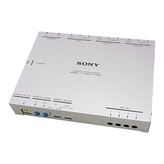
TV tuner unit
TV Antenna
Wireless Remote Commander
Tuner unit
Reception format
PAL
Power requirements
12 V DC, from car battery
(negative ground)
Power consumption
Approx. 0.5 A
Inputs
Video/audio (Sony BUS compatible)(1)
Sony BUS (1)
TV aerial (4)
Outputs
Video/audio (Sony BUS compatible)(2)
Sony BUS (1)
Approx. 185.5 × 31 × 137 mm
Dimensions
(W × H × D)
Mass
Approx. 0.7 kg
Channel coverage
CCIR
CHINA
2 - 4
1 - 5
CH
CH
VHF LOW
48.25
-
49.75
MHz
MHz
62.25
85.25
MHz
MHz
5 -12
6 - 12
CH
CH
VHF HIGH
175.25
-
168.25
MHz
MHz
224.25
216.25
MHz
MHz
21 - 69
13 - 57
CH
CH
UHF
471.25
-
471.25
MHz
MHz
855.25
863.25
MHz
MHz
IF VIDEO
38.90
38.90
MHz
MHz
IF AUDIO
33.40
32.40
MHz
MHz
Sony Corporation
9-874-168-01
2002I0500-1
e Vehicle Company
C 2002.09
Published by Sony Engineering Corporation
XT-P50V
VCA-116
RM-X124
SPECIFICATIONS
UK
ITALY
AUSTRALIA
–
A - C
0 - 4
CH
CH
-
53.75
-
46.25
MHz
MHz
–
82.25
95.25
MHz
MHz
–
D - H2
5 - 12
CH
CH
-
175.25
-
102.25
MHz
MHz
–
224.25
224.25
MHz
MHz
21 - 69
21 - 69
28 - 69
CH
CH
CH
-
471.25
-
471.25
-
527.25
MHz
MHz
MHz
855.25
855.25
814.25
MHz
MHz
MHz
38.90
38.90
38.90
MHz
MHz
MHz
32.90
33.40
33.40
MHz
MHz
MHz
XT-P50V
Wireless remote commander RM-X124
Power requirements
Operable range
Dimension
Mass
Design and specifications are subject to change without notice.
-
-
-
AEP Model
UK Model
E Model
Australian Model
Chinese Model
CR2025 lithium battery
Approx. 2.5 m
50 × 86 × 11.5 mm (W × H × D)
Approx. 36 g (including a battery)
MOBILE TV TUNER
Advertisement
Table of Contents

Related Manuals for Sony XT-P50V


Summary of Contents for Sony XT-P50V
- Page 1 XT-P50V SERVICE MANUAL AEP Model UK Model Ver 1.0 2002.09 E Model Australian Model Chinese Model The XT-P50V is composed of the following models. TV tuner unit XT-P50V TV Antenna VCA-116 Wireless Remote Commander RM-X124 SPECIFICATIONS Wireless remote commander RM-X124...
-
Page 2: Table Of Contents
To the power remote cord (blue) of the monitor* Blue (when connected to the monitor) Blau * If the Sony BUS connection is used, this connection is not necessary. an Stromversorgungskabel (blau) eines Monitors* (bei Anschluss an einen Monitor) - Page 3 XT-P50V RCA interconnects 3 (5.3 m) Bus cable 2 (5.3 m) Cinch-Verbindungen 3 (5,3 m) Buskabel 2 (5,3 m) Leave clearance of at least 50 mm. Mindestens 50 mm Abstand lassen. Short CONTROL Kurz OUTPUT CONTROL Do not bend sharply.
- Page 4 The XAV-7W is shown for the Sony BUS connection and the • Do not wipe the aerial body, rods, or cables with alcohol, installation. Wet conditions will reduce the adhesive strength XVM-R75 is shown for the other connection in this operating and may cause the aerials to fall off.
-
Page 5: Test Mode
TEST MODE ELECTRICAL ADJUSTMENTS MICROPROCESSOR VERSION CHECK DIVERSITY VCO FREQUENCY ADJUSTMENT Connection: Checking Method: 1. Set TV SYSTEM switch of XT-P50V to 2. frequency 2. Connect XAV-7W and turn on the power for OFF screen sta- counter TP130 tus. TV Tuner Unit 3. - Page 6 XT-P50V Adjusting and Connecting Location: – HIDEAWAY BOARD (Component Side) – J104 INPUT VIDEO jack RV100 OSD Adjustment CT100 Diversity VCO Frequency Adjustment – HIDEAWAY BOARD (Conductor Side) – TP139 TP130 TP131...
-
Page 7: Diagrams
XT-P50V SECTION 4 DIAGRAMS 4-1. BLOCK DIAGRAM – AUDIO Section – L101 L103 L102 VIDEO +31V (Page 8) ANT IN NOISE CANCELLER IC104 +B 9V, +B 9V, +B 5V, VIDEO • R-ch is omitted due to same as L-ch. 35mA... -
Page 8: Block Diagram -Video Section
XT-P50V 4-2. BLOCK DIAGRAM – VIDEO Section – VIDEO SELECT SWITCH, ON SCREEN DISPLAY VIDEO AMP VIDEO AMP CONTROLLER IC106 IC109 IC110 VIDEO J103 (2/2) V OUT OUTPUT1 (Page 7) 10 CVIN VOUT VIDEO J103 (2/2) DATA INPUT CONTROL VIN2... -
Page 9: Block Diagram -Bus Control/Power Supply Section
XT-P50V 4-3. BLOCK DIAGRAM – BUS CONTROL/POWER SUPPLY Section – BUS ON/OFF SWITCH Q109 CN101 CONTROL CN103 (FOR CHECK) SONY BUS (SONY BUS) INTERFACE LINKOFF IC101 SIRCS CLK OUT SCLK SCLK CLOCK UNI CLK DATA DATA OUT DATA UNI SI... -
Page 10: Note For Printed Wiring Board And Schematic Diagrams
XT-P50V 4-4. NOTE FOR PRINTED WIRING BOARD AND SCHEMATIC DIAGRAMS • Waveforms Note on Printed Wiring Board: Note on Schematic Diagram: 1 IC100 1 (CT) 6 Q200-1 (Drain) qa IC113 3 • X : parts extracted from the component side. -
Page 11: Schematic Diagram -Hideaway Board (1/3)
XT-P50V 4-5. SCHEMATIC DIAGRAM – HIDEAWAY Board (1/3) – • • See page 10 for Waveforms. See page 16 for IC Block Diagrams. TU100 (1/3) TV TUNER UNIT (V5-E60CT) ANT IN Q100 Q103 ANTENNA 1 SWITCH ANTENNA 3 SWITCH Q101... -
Page 12: Schematic Diagram -Hideaway Board (2/3)
XT-P50V 4-6. SCHEMATIC DIAGRAM – HIDEAWAY Board (2/3) – • • See page 10 for Waveforms. See page 16 for IC Block Diagrams. C262 (2/3) J103 R279 D132 R151 MA3091WK VIDEO BUS_L R156 C209 R276 INPUT 0.01 R274 C261 C203... -
Page 13: Schematic Diagram -Hideaway Board (3/3)
C190 R229 R288 R289 C272 R292 R287 47 16V 4.7k 4.7k DETECT 100k SYSTEM CONTROLLER CONTROL TP800 C187 OTHERS OTHERS (FOR SONY BUS) 0.01 IC108 C217 D123 M38039FFFP-081 C186 C137 L106 MA729 R211 0.01 R228 0.01 22µH C216 100k TP804... -
Page 14: Hideaway Board (Component Side)
XT-P50V 4-8. PRINTED WIRING BOARD – HIDEAWAY Board (Component Side) – • Semiconductor Location Ref. No. Location D100 D101 C-14 D102 HIDEAWAY BOARD (COMPONENT SIDE) D103 D104 D105 D107 D108 D109 D111 R279 D138 D112 Q119 Q118 R220 D113 R288... -
Page 15: Printed Wiring Board -Hideaway Board (Conductor Side)
PRINTED WIRING BOARD – HIDEAWAY Board (Conductor Side) – • Semiconductor Location HIDEAWAY BOARD Ref. No. Location (CONDUCTOR SIDE) CN100 CN101 J104 J102 J103 D110 CONTROL OUTPUT2 OUTPUT1 INPUT (FOR SONY BUS) D115 AUDIO VIDEO AUDIO VIDEO AUDIO VIDEO D116 D117 I-12 D118 I-12 D120 D133 CN100 CN101... - Page 16 XT-P50V • IC Block Diagrams IC100 TL1451ACDB IC101 BA8272F-E2 IC104 TA2005SN BUFF PILOT CANCEL BUFF PULSE TRIGGER GATE VERF. BUFF +2.5V – BUFF RESET REFERENCE SWITCH VOLTAGE ERROR AMP2 COMPA- RATOR2 +2.5V VERF OUTPUT2 SHORT CIRCUIT VERF VERF PROTECTION COMPARATOR OUTPUT1 –...
- Page 17 XT-P50V IC111 NJM2123V (TE2) IC116 S-875271CUP-AHA-T2 PROTECT SW 2 CIRCUIT IN2 A+ V OUT V IN IN1 A+ IN2 A– REGULATOR VOLTAGE DETECT IN1 A– OUT2 OUT1 IN2 B– POWER ON/OFF IN1 B– IN2 B+ IN1 B+ SW R SW C...
-
Page 18: 4-10. Ic Pin Function Description
Battery detection signal input “H”: battery on BUCKUP VPP signal input terminal System reset signal input from the SONY bus interface and reset signal generator “L”: reset RESET For several hundreds msec. after the power supply rises, “L” is input, then it changes to “H”... - Page 19 XT-P50V Pin No. Pin Name Description Destination setting terminal of TV tuner unit NICAM Normally: fixed at “L”, “H”: hong kong and south africa area models N.C.O Not used OSD data clear control signal output to the on screen display controller “L”: all clear 55, 56 N.C.O...
-
Page 20: Exploded View
XT-P50V SECTION 5 EXPLODED VIEW NOTE: • -XX and -X mean standardized parts, so they • Items marked “*” are not stocked since they may have some difference from the original are seldom required for routine service. Some one. delay should be anticipated when ordering •... -
Page 21: Electrical Parts List
XT-P50V SECTION 6 ELECTRICAL PARTS LIST HIDEAWAY NOTE: • Due to standardization, replacements in the • Items marked “*” are not stocked since they When indicating parts by reference parts list may be different from the parts speci- are seldom required for routine service. - Page 22 XT-P50V HIDEAWAY Ref. No. Part No. Description Remark Ref. No. Part No. Description Remark C185 1-107-826-11 CERAMIC CHIP 0.1uF C254 1-128-526-11 ELECT 100uF C186 1-163-021-11 CERAMIC CHIP 0.01uF C255 1-126-795-11 ELECT 10uF C256 1-126-795-11 ELECT 10uF C187 1-163-021-11 CERAMIC CHIP 0.01uF...
- Page 23 XT-P50V HIDEAWAY Ref. No. Part No. Description Remark Ref. No. Part No. Description Remark D127 8-719-026-18 DIODE MA3091WK L105 1-410-687-11 INDUCTOR CHIP 1.2MH D128 8-719-801-78 DIODE 1SS184 L106 1-414-755-11 INDUCTOR CHIP 22uH D129 8-719-422-16 DIODE MA8039-L-TX L107 1-412-030-11 INDUCTOR CHIP 22uH...
- Page 24 XT-P50V HIDEAWAY Ref. No. Part No. Description Remark Ref. No. Part No. Description Remark R121 1-216-033-00 METAL CHIP 1/10W R184 1-216-864-11 SHORT CHIP R185 1-216-864-11 SHORT CHIP R122 1-216-817-11 METAL CHIP 1/10W R187 1-216-803-11 METAL CHIP 1/10W R123 1-216-817-11 METAL CHIP...
- Page 25 XT-P50V HIDEAWAY Ref. No. Part No. Description Remark Ref. No. Part No. Description Remark R259 1-216-833-11 METAL CHIP 1/10W < VIBRATOR > R260 1-216-833-11 METAL CHIP 1/10W X100 1-567-890-51 VIBRATOR, CRYSTAL (8MHz) R261 1-216-857-11 METAL CHIP 1/10W X101 1-567-504-11 OSCILLATOR, CRYSTAL (4.434MHz)
- Page 26 XT-P50V Ref. No. Part No. Description Remark Ref. No. Part No. Description Remark PARTS FOR INSTALLATION AND CONNECTIONS ************************************** 3-310-656-01 TAPE, MAGIC 3-310-658-01 TAPE (B), MAGIC 1-824-788-11 CORD, CONNECTION (POWER) 1-590-519-21 CORD (WITH CONNECTOR) (BUS) HOOK-AND-LOOP TAPE BUS CABLE 1-824-336-11 CORD, CONNECTION (RCA) ×...