
Related Manuals for Sony MVS-8000X SystemMVS-7000X System


Summary of Contents for Sony MVS-8000X SystemMVS-7000X System
- Page 1 Multi Format Switcher System MVS-8000X System MVS-7000X System (With CCP-8000 Series Center Control Panel) User’s Guide Volume 1 [English] Software Version 12.10 and Later 1st Edition (Revised 2)
- Page 2 NOTICE TO USERS © 2011, 2013 Sony Corporation. All rights reserved. This manual or the software described herein, in whole or in part, may not be reproduced, translated or reduced to any machine readable form without prior written approval from Sony Corporation.
- Page 3 Functions Newly Supported in Version 12.10 The functions newly supported in the MVS-8000X/7000X system version 12.10 are as follows. Functions relating to operability Functions See page Classifi- Menu cation supported Vol.1 Vol.2 Transitions AUX MIX 3232 Chapter Chapter transitions 7333.12 3 Chapter Functions relating to the switcher Functions...
-
Page 4: Table Of Contents
Chapter 2 Menus and Control Panel Table of Contents Names and Functions of Parts of the Control Panel ........30 Control Panel: Example Configuration 1 Volume 1 (With Standard Transition Modules) ..........30 Control Panel: Example Configuration 2 (With Simple Transition Modules) ... 31 Chapter 1 MVS-8000X/7000X Control Panel: Example Configuration 3 Functions... - Page 5 CCP-6324 3M/E Control Panel ....71 Bus Selection ..........89 Cross-Point Control Block (CCP-6224/6324) AUX Panel-less Function ......92 in AUX Operating Mode ....72 Signal Assignment and Selection ....92 Multifunction Flexi Pad Control Block ..73 Signal Name Display ........94 Basic Menu Operations ......
- Page 6 Simple Transition ........120 Applying a DME Effect to a Key ....146 Basic Operations for Simple Other Key Setting Operations ....148 Transitions ........120 Key Adjustments (Multifunction Flexi Pad Display of the Key Output Status and Key Control Block) ........149 Priority ..........
- Page 7 Saving, Canceling, and Deleting Edited Wipe Chapter 7 Frame Memory Patterns ..........182 Overview ..........202 Still Image Operations ......204 Preparations ..........204 Chapter 6 DME Wipes Interpreting the Frame Memory Menu ..204 Overview ..........183 Selecting an Input Image ......206 Types of DME Wipe Pattern ......
- Page 8 Secondary Color Correction Operations... 245 Chapter 8 Color Backgrounds, Copy Luminance Processing Operations ..... 245 and Swap, and Other Settings Spot Color Adjustment ......246 Output Video Processing Operations ..247 Color Background ........228 YUV Clip Operations ........ 248 Color Background Settings Menu .....
- Page 9 Transformation Operation Modes ....271 Applying Special Effects (Nonlinear Effect Settings) ..........313 Graphics Display ........273 Wave Settings ..........313 Three-Dimensional Parameter Display ..274 Mosaic Glass Settings ........ 315 Special Effects ........... 274 Flag Settings ..........315 Global Effects ..........282 Twist Settings ..........
-
Page 10: Volume 2
Corner Pinning Settings ......347 Effect Menu ..........383 Global Effect Operations ......349 Snapshot Menu .......... 384 Overview ........... 349 Shotbox Menu ........... 385 Operations Common to All Global File Menu ..........386 Effects..........349 Engineering Setup Menu ......387 Combiner Settings ........ - Page 11 Control of VTRs, Extended VTRs, and Disk Keyframe Loop (Repeated Execution of a Recorders ......... 421 Specified Range) ......453 Manual Operation ........421 Undoing an Edit Operation ......454 Controlling the Tape/Disk Transport ..422 Duration Mode Setting ....... 454 Checking VTR/Disk Recorder/Extended VTR Transition Mode Settings for User Information ........
- Page 12 Block ..........490 Chapter 14 Snapshots Creating a Shotbox Register Using the Menus ..........491 Overview ..........472 Shotbox Execution ........493 Snapshot Types ......... 472 Shotbox Execution From the Numeric Keypad Snapshot Attributes ........472 Control Block ........493 Snapshot Operations From the Numeric Shotbox Execution in the Flexi Pad Control Keypad Control Block ......
- Page 13 Macro Editing Using Menus ....511 Importing Frame Memory Data ...... 540 Macro Register Editing ......511 Exporting Frame Memory Data ...... 541 Online Editing of Macro Events ....511 Directory Operations ....... 542 Offline Editing of Macro Events ....514 Displaying the Directory Menu ......
- Page 14 Reset and Initialization (Initialize Assigning a Region to the Region Selection Menu) ..........555 Buttons in the Numeric Keypad Control Block or Multifunction Flexi Pad Installation and Device Setup (Install/Unit Control Block ........570 Config Menu) ........555 Setting Transition Control Block Button Installing Software ........
- Page 15 Exporting Source Names and Destination Settings for the Flexi Pad and Wipe Snapshot Names ..........584 Menu ..........604 Making Settings for Audio Mixer ....584 Setting the Button Operation Mode ...... 604 Assigning a Cross-Point Button to Enable/ Setting the Operation Mode of the [ALL] Disable Side Flags ......
- Page 16 Selecting the Primary Input to be Used in the Setting the Interface Between the DME and Format Converter ......614 the Switcher ........633 Setting the Frame Delay Function ....614 Setting the AUX Bus Output and Reentry Input ..........634 Selecting the Format Converter Conversion ........
- Page 17 Releasing the Assignment of a GPI Output Serial Tally Settings (Serial Tally Port ..........644 Menu)..........658 GPI Output Settings (GPI Output Assign Setting or Changing the Serial Tally Menu) ..........644 Settings..........658 Making DCU GPI Output Settings ..... 644 Making the Serial Tally Source Address Settings..........
- Page 18 Correspondence Between Events and Symbols ........... 667 Symbols and Parameters ......668 Example of File Contents ......672 About the Macro Attachment List Display ..........673 M/E and PGM/PST Banks ....... 673 Auxiliary Bus Control Block ....674 Other Blocks ..........675 Menu Operations Not Recorded in a Menu Macro ..........
-
Page 19: Chapter 1 Mvs-8000X/7000X Functions
MVS-8000X/7000X Functions Chapter System nomenclature Introduction The following terms are used for systems, depending on the combination of installed options, and the signal format. System configuration and features Term for system This manual is the User’s Guide for the MVS-8000X/ System with installed option boards HD system 7000X Multi Format Switcher system. -
Page 20: Features Of The Mvs-8000X/7000X Multi Format Switcher System
Powerful external device interfaces By connecting to a Sony routing switcher or similar, a large system can be built. From the control panel, it is also possible to operate other equipment, including VTRs and disk recorders. -
Page 21: Basic Video Processing
Powerful frame memory functions Basic Video Processing The frame memory can hold approximately 1000 frames in an HDTV system (approximately 2000 frames in 720P/ 59.94 format), or approximately 5000 frames in an SDTV system in 480i/59.94 format, or approximately 4000 This section introduces basic functions used for video frames in 576i/50 format, and allows eight frames (four frames in 1080P format) to be recalled simultaneously. - Page 22 cross-point selections on the A and B buses are Simultaneously changing the background interchanged. and keys You can change any of the eight keys (downstream keys on Inserting and deleting a key the PGM/PST bank) and the background at the same time. You can insert one or more of the eight keys (downstream keys on the PGM/PST bank).
-
Page 23: Keys
• Clip transition • Cut Transition type: wipe There are two modes for carrying out a transition: auto transitions are carried out by a button operation, and manual transitions are carried out using the fader lever. It is also possible to combine these two modes. Independent Key Transitions In addition to common transitions, it is possible to carry out independent transitions on the keyers of the M/E banks... -
Page 24: Wipes
is termed the “key fill.” The system component • Random and diamond dust wipe patterns responsible for processing a key is referred to as a keyer. Each switcher bank has eight keyers, each providing the You can combine two selected patterns (referred to as “main”... -
Page 25: Copy And Swap
frame, when these areas are filled with a separate image Copy and Swap selected from the utility 1 bus. This function can be used to copy and swap the settings among the M/E-1 to M/E-3, and PGM/PST banks or between keyers. The following settings can be copied or swapped. -
Page 26: 3D Support
Program output for “Main” 3D Support Background B Installing the switcher upgrade software in an MVS- Background A 8000X/ 7000X, and the DME upgrade software in an MVE-8000A, MVE-9000, or MKS-7470X/7471X, enables the processing of video in 3D mode. For details, see “3D Support” (page 260). Key (Key 1 to Key 8 are available on the main side.) Program output for “Sub”... -
Page 27: Creation Of Special Effects And Management Of Data And Operations
• Devices supporting P-Bus (Peripheral II protocol) • Devices supporting GPI of Data and Operations • VTRs • Disk recorder (Sony disk 9-pin protocol and video disk communications protocol, Odetics protocol) This section introduces functions used for creation of • Extended VTR (Abekas A53 protocol) special effects, control of external devices or switcher operations, and data management. -
Page 28: Snapshots
Menu macros Snapshots The term “menu macro” refers to the function whereby a sequence of menu operations is saved as data in memory, The term “snapshot” refers to a function whereby the so that it can be recalled as required to automatically various settings required to apply a particular effect to an execute the same sequence of operations. -
Page 29: Setup
Setup Various settings are required, in order to operate the switcher, control panel, DME, external devices, and so on, connected together in a single system. This is referred to as “setup,” and you can carry out the setup operations from the Engineering Setup menu. The settings in the Engineering Setup menu are grouped under the following headings. -
Page 30: Chapter 2 Menus And Control Panel
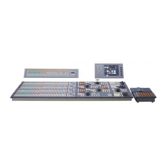
Menus and Control Panel Chapter Names and Functions of Parts of the Control Panel The maximum number of M/E banks supported by the Notes MVS-8000X/7000X system is given below. • On the MVS-8000X, M/E-5 cannot be used. M/E-5 MVS-8000X operation and settings are disabled, even if they appear Five M/E banks maximum (PGM/PST, M/E-1 to M/E-4) in the menu. -
Page 31: Control Panel: Example Configuration 2 (With Simple Transition Modules)
Keyframe control block (page 51) Menu control block (page 59) Key control block (page 42) Auxiliary bus control block (page 56) Device control block (page 45/ page 48) Memory card/USB adaptor block (page 60) “Memory Stick”/USB connections block (page 60) M/E-1 bank Utility/ Shotbox... -
Page 32: Control Panel: Example Configuration 3 (With Compact Transition Modules)
Control Panel: Example Configuration 3 (With Compact Transition Modules) The following illustration shows a typical configuration, with compact transition modules used in the transition control block. Transition control block (compact type) (page 68) Control panel configuration 3 (with compact transition modules) Cross-Point Control Block In the cross-point control block, you can select the signals to be used in this M/E bank or PGM/PST bank. - Page 33 Reentry buttons Key 2 row Key 1 row 7 M/E bank display 3 Key bus selection buttons 1 Cross-point buttons 8 Macro buttons Reentry buttons Background B row 4 UTIL button 6 Dedicated SHIFT button Background A row 2 XPT HOLD buttons 5 Source name displays a Cross-point buttons Name...
- Page 34 Assigning a delegation function to the key Name Description 1 row • The buttons in this row select the key 2 or Key 2 row key 4 signals to be inserted into the video You can assign the key/AUX bus delegation function to on this M/E bank or PGM/PST bank.
- Page 35 • Every time the button is pressed, it toggles between the Name Description on and off states for key 1 and key 2 rows. For • Use this button to set a macro attachment background A and background B rows, utility buses PRE MCRO (pre macro) remain disabled.
-
Page 36: Cross-Point Control Block In Key/Aux Bus Delegation Mode
Cross-Point Control Block in Key/AUX Bus Delegation Mode For details of assignment, see “Assigning a Key or AUX You can assign key and AUX buses to the key 1 row Bus to a Button in the Key 1 or Key 2 Row” in Chapter 19 buttons in the cross-point control block for use as delegation buttons so that signal selection can be made in (Volume 2). -
Page 37: Transition Control Block (Standard Type)
e DSPLY [display] button f DEST button Press to light this button, in order that the source name / When both the [DSPLY] button and this button are on, the bus name displays show the signal names or bus names key bus names or AUX bus names are displayed. - Page 38 Name Description In a background transition, the new video fades in as the current video fades out. NAM (non- The current and new video signals are additive mix) compared, and the signal with the higher luminance level is given priority in the output. SUPER MIX The current video is maintained at 100% Name Description...
- Page 39 Name Description • This shows the “transition rate” (the time Transition rate display from the beginning of a transition to its completion) set for an auto transition, in frames. • You can set the transition rate using the Name Description numeric keypad control block, Flexi Pad Pressing this button, turning it on, enables the control block, or menu.
-
Page 40: Flexi Pad Control Block (Standard Type)
j Key delegation buttons Name Description These buttons delegate this independent key transition • Press the corresponding one of these control block to a desired keyer. Press one of the [KEY1] KEY1 ON to KEY8 ON to [KEY8] buttons (or the [DSK1] to [DSK8] buttons in buttons to cut key 1 to key 4 in or out (DSK1 ON instantaneously. - Page 41 Name Description 1 Mode selection buttons EFF (effect) To recall the master timeline or run an effect, use this in combination with the buttons in the 5 XPT HOLD status display memory recall section. 6 Numeric display SHOTBOX To recall or execute a shotbox, use this in 4 UNDO combination with the buttons of the memory button...
-
Page 42: Key Control Block
e XPT HOLD (cross-point hold) status display Name Description A bus for which cross-point hold is set appears as a green • After recalling a register, press this button to light. UNDO return to the state before recalling the f Numeric display register. - Page 43 Name Description Name Description • Use the signal selected on the key fill bus, AUTO SEL Press one of the [M/E 1] to [M/E 5], and [P/P] buttons to select the bank (an M/E bank or the (selection) delegation and the paired key source signal. The PGM/PST bank) to which the key control setting of key fill and key source pairs is block is delegated.
- Page 44 A maximum of four consecutively numbered DME Name Description channels from the two sets, DME 1 to 4 and DME 5 to 8, Apply a border of a uniform thickness to the can be assigned to one keyer. (border) whole key. On the MVS-8000X, when the signal format is 1080P DROP BDR Apply a border to two sides of the key (for...
-
Page 45: Device Control Block (Trackball)
transition), hold down this button, and press the DME Name Description channel selection button. • When you press this button, it lights FM FEED (frame momentarily amber, then for the currently m TRACE button memory selected keyer, the key processed signals When a DME channel is already allocated to another keyer feed) are selected for frame memory sources 1... -
Page 46: Operation Buttons
Overview of assigned operation Selected buttons [FX CTRL] Leave this button off for operation. Alternatively, for details of operation of this button, refer to the help information for the MPES-FX01 Programmable Effector software. b Operation buttons The following buttons are used to carry out the Selected Overview of assigned operation corresponding operations. - Page 47 Name Description Name Description • When this button is pressed, the pattern • Pressing this button once returns the two- SHIFT/CLR (center) WORK position returns to the center. dimensional transformation settings to the • When the [USER] button is selected, the BUFR (clear defaults.
-
Page 48: Device Control Block (Joystick)
When the effect run control mode is enabled When the [LOC SIZE], [LOC XYZ], or [ASP PS] button By turning the Z-ring, you can run the keyframe effect, is held down, the trackball operation is switched to fine independent of the STOP NEXT KF, EFF LOOP, and control (fine mode). -
Page 49: Device Control Block (Search Dial)
• The button on the end of the joystick When the resizer control mode is enabled • [LOC SIZE] button Move for operations in the X-, Y-, and Z-axes. • [LOC XYZ] button When the following buttons are held down, the joystick •... - Page 50 c SBOX (shotbox) buttons Name Description Assign a shotbox saved in registers 1 to 99. When you • When pressed, these buttons light green, SET START press a button, the assigned shotbox is selected, and “START TC”, “STOP TC” or “DUR” appears TC, SET executed.
-
Page 51: Keyframe Control Block
Name Description Name Description • When pressed simultaneously with the Sets the search dial to jog mode. [PLAY] button, this button lights red (the SHTL Sets the search dial to shuttle mode. [PLAY] button lights amber), and the image (shuttle) from the selected device is recorded. - Page 52 Name Description • When this button is pressed, a new INS (insert) keyframe is inserted after the current keyframe. • Pressing this button while holding down the [SHIFT] button inserts a new keyframe before the current keyframe. • During macro editing, pressing this button registers an event after the current event.
- Page 53 Name Description UNDO When this button is pressed, the last executed keyframe (during macro editing, macro event) Effect indicator insertion, modification, or deletion, or paste operation is canceled. d Duration setting buttons The following buttons are used to set the duration of a keyframe.
-
Page 54: Numeric Keypad Control Block
i STOP NEXT KF (stop next keyframe) button AUTO INS (auto insert) button When this button is pressed, turning it on, the effect When editing a macro, press this button, turning it on, to execution range is from the current time to the next enable the auto insert function, so that every control panel keyframe. - Page 55 Name Description Name Description • Select all regions. RCALL Press this button to switch to the mode for • When any region is already selected, (recall) recalling a snapshot, effect, shotbox or macro from a register. pressing this button makes all regions unselected.
-
Page 56: Fade To Black Control Block
Fade to Black Control Block Name Description When this button is pressed, the signal (preset) selected on the background B row of the 3 AUTO button PGM/PST bank is selected on the edit preview bus. 1 FTB button M/E 1 to The preview signal (M/E-1 PVW, M/E-2 PVW, M/E 5, P/P M/E-3 PVW, M/E-4 PVW, M/E-5 PVW, P/P... - Page 57 3 DEST button m Level selection buttons k AUX mix buttons l RTR button 2 Selected source name displays 8 2ND button 1 AUX delegation buttons 7 KEY button 9 Source name displays 4 Selected bus display 6 XPT HOLD buttons 5 Cross-point buttons 0 SHIFT button a AUX delegation buttons...
-
Page 58: Auxiliary Bus Control Block (For Router Control)
l RTR (router) button In the case of a module without source name displays, this button is invalid. Press this button, turning it on, to assign the auxiliary bus control block to router control. k AUX mix buttons When AUX bus is selected using the AUX delegation For details of the names and functions of parts for router button, press this button to execute an AUX mix transition. -
Page 59: Menu Control Block
See “Using the Auxiliary Bus Control Block for Router If the source names and destination names are set in the Setup menu to “Sw’er Local” mode, then the description Control Setting Button” in Chapter 19 (Volume 2). names appear here. h 2ND button c DEST (destination) button After selecting a destination with the destination selection... -
Page 60: Memory Card/Usb Adaptor Block
Knobs These adjust the parameter values appearing in the menu. For details on the devices that can be connected, consult your Sony representative. d User preference buttons These recall the functions or menus assigned to them in the Setup menu. -
Page 61: Utility/Shotbox Control Block
For details on the devices that can be connected, consult • Do not strike, bend, or drop the “Memory Stick.” your Sony representative. • Do not disassemble or modify the “Memory Stick.” • Do not allow the “Memory Stick” to get wet. -
Page 62: Transition Control Block And Flexi Pad Control Block (Simple Type)
b Memory recall buttons button goes off). In the case of a shotbox function, pressing You can use these buttons to recall frequently used menus, the button executes the assigned shotbox function, and the utility functions, shotbox registers, or macro registers that button lights yellow. - Page 63 Transition control block and flexi pad Name Description control block (with [INH] button) In a background transition, the new video fades in as the current video fades out. qs INH button NAM (non- The current and new video signals are additive mix) compared, and the signal with the higher luminance level is given priority in the output.
- Page 64 appears over key 2 on the program monitor, the OVER Name Description indicator for key 1 lights. • Move this vertically to carry out a transition. The following is the Flexi Pad control block. Fader lever • When a transition type selection button to g Mode selection buttons which the [KF] button function has been assigned is lit, you can use this as a key...
-
Page 65: Independent Key Transition Control Block (Simple Type)
Name Description Independent Key Transition Control Switches the key with a DME wipe. Block (Simple Type) Inserted or deleted instantaneously. • When setting is made in the Setup menu to The left side of this control block controls key 3, and the SHIFT right side controls key 4. -
Page 66: Downstream Key Control Block
For details, see the section “Assigning a Function to the Independent Key Transition Control Block (Simple Type)” in Chapter 19 (Volume 2). Downstream Key Control Block 1 Key delegation buttons 5 Key source name display/key snapshot buttons 4 Key snapshot setting buttons 2 Independent key transition type selection... -
Page 67: Downstream Key/Fade-To-Black Control Block
Downstream Key/Fade-to-Black Name Description Control Block • Press these to instantaneously cut the DSK1 (downstrea downstream keys 1, 2, 3, and 4 in. m key 1) • When a key is already inserted, pressing ON to DSK4 the button cuts it out. 4 Key source name display/key snapshot buttons ON buttons •... -
Page 68: Transition Control Block (Compact Type)
g Preview selection buttons Name Description Press one of these buttons to select a signal on the edit • Press these to cut in the corresponding preview bus. Each of these buttons can be assigned to any DSK1 ON, DSK2 ON downstream key 1 or 2. - Page 69 2 Transition type selection buttons 6Key status display 1 Next transition selection buttons 8 Independent key transition execution 7 PRIOR SET button section 4 Wipe direction selection buttons 3 Transition execution section 5 TRANS PVW button a Next transition selection buttons b Transition type selection buttons Press these buttons, turning them on, to determine what the You can assign these buttons in setup to any transition...
- Page 70 Name Description Name Description • Pressing this button carries out an auto The color matte (unpatterned display) is PST (preset) AUTO COLOR MIX inserted during transition, replacing the TRANS transition of the set transition rate current video by the color matte, and then (transition) (duration).
-
Page 71: Ccp-6224 2M/E Control Panel
For details, see “Setting the Key Priority in the Transition buttons: Press the corresponding one of these buttons Control Block” (page 98). to cut key 1 to key 8 in or out automatically at the set transition rate. When the key corresponding to the h Independent key transition execution section button appears in the final program output, the button KEY1 TRANS (transition) to KEY8 TRANS (DSK1... -
Page 72: Cross-Point Control Block (Ccp-6224/6324) In Aux Operating Mode
2 Transition control block (compact type) 3 Device control block (trackball) 4 Multifunction Flexi Pad control block 1 Cross-point control block a Cross-point control block c Device control block (trackball) For details of operations, see “Cross-Point Control For details of operations, see “Device Control Block Block”... -
Page 73: Multifunction Flexi Pad Control Block
For details of AUX mix transition operation, see “AUX used as AUX bus cross-point selection buttons, with the Mix Transitions” (page 119). source name display showing the source names or the bus names (AUX panel-less function). c AUX CTRL (AUX control) button This switches the cross-point control block to the AUX AUX delegation buttons operating mode. - Page 74 4 Alphanumeric display 1 Mode selection buttons 2 EDIT ENBL button 7 Adjustment knobs 3 Region selection buttons 5 Memory recall section 6 Adjustment knob displays a Mode selection buttons b EDIT ENBL (edit enable) button Pressing the following buttons selects the mode. By pressing this, turning it on, you can carry out the following operations.
-
Page 75: Basic Menu Operations
Name Description Basic Menu Operations M/E 1, Select the M/E-1, M/E-2, and PGM/PST M/E 2, P/P regions respectively. USER4 Selects the USER4 region. Overview DEV1 Selects the device 1 region. • Displays buttons in the memory recall MORE In the MVS system, all detailed settings for basic section for regions not assigned to a region selection button, so that they can be operations such as transitions, keys, wipes, and DME are... -
Page 76: Accessing Menus
• Changing the top menu selection button assignment in To display the top menu from the top menu setup has no effect on the top menu list. list In the same way as for the top menu selection buttons in To shut down the menus the menu control block, press each button to display the particular top menu in the menu display. -
Page 77: Example Of Displaying A Menu
Buttons Menus Function MISC Misc Settings for side flag, safe title, transition page 233 settings, and connection to external devices STATS Status Status display page 236 DME special effect settings page 288 GLB EFF Global Effect Global effect settings page 349 Router Router settings page 237... - Page 78 qs b (previous) button and B (next) button 5 Status area 6 Function button area 2 Menu page number button 7 Parameter group button 0 Keyframe status 1 Menu title button 4 HF buttons 9 Previous page button qa Default recall button 8 Knob parameter buttons 3 VF buttons M/E-1 >Key1 >Type menu...
- Page 79 indication [Parent] appears, this displays the parent 1) When an external hard disk drive is connected directory. c VF buttons These indicate the larger subdivisions of this menu. j Keyframe status Depending on the selected item, the menu screen contents This shows the keyframe status of the reference region.
-
Page 80: Names And Functions Of Parts Of The Top Menu Window
Names and Functions of Parts of the Top Menu Window 1 Top menu selection buttons 8 Shut down button 7 Add Favorite button 6 Close button 2 Input display 3 Numeric entry section 4 Clear button 5 Enter button a Top menu selection buttons g Add Favorite button These are the same as the top menu selection buttons in the Pressing this button allows the currently displayed menu to... -
Page 81: Names And Functions Of Parts Of The Numeric Keypad Window
c Input value Names and Functions of Parts of the This is the value being input into the numeric keypad Numeric Keypad Window window. d Close button 1 Item display This closes the numeric keypad window. 2 Max./min. value indication e TC (timecode) button 3 Input value When the numeric keypad window is opened for a setting... -
Page 82: Names And Functions Of Parts Of The Color Pallet Window
1 Item display 2 Input string 3 Close button 4 BS button qd Line feed button 5 Caps Lock button qs Enter button 6 Shift button 7 Space button qa Right button 8 Clear button 0 Left button 9 Del button a Item display g Space button This is the name of the parameter being set in the keyboard... - Page 83 1 Color palette buttons 2 Operation buttons 3Color display 4 Numeric keypad a Color palette buttons d Numeric keypad Press one of these to enter the corresponding color in the Use this to enter numeric values for parameters. display. By default the following settings are available. For details of use, see page 81.
-
Page 84: Menu Operations
Pressing a button of this type displays a further menu, Menu Operations allowing more detailed settings (Example: [Chroma Adjust] in the Type menu). The method of menu operation is basically the same when Setting Parameters using a mouse with an external monitor, but with mouse clicks in place of button presses. -
Page 85: Going Back To The Previous Menu
To switch the subsidiary menu site on and Notes The default recall function does not return the horizontal Assign [SUB MENU SITE] to a menu control block top (H) and vertical (V) position settings to their default state menu selection button or user preference button. individually. -
Page 86: Shortcut Menu
Shortcut Menu Registering a Menu To the Shortcut Menu In the Home >Favorites >Shortcut menu, select the desired group. Display the menu you want to register, and then press Press [Group Edit]. [Add Favorite]. The following menu appears. The currently displayed menu is automatically registered to a blank button. - Page 87 Press [Clear]. This completes the assignment of the menu to the button. A confirmation message appears. Repeat steps 2 to 8 to complete the “Favorites” menu. Press [Yes]. This deletes the settings. To copy button settings To register a menu on a button In the Home >Favorites >Button Edit menu, press the You can register 15 buttons in one group.
-
Page 88: Chapter 3 Signal Selection And Transitions
Signal Selection and Transitions Chapter Video Processing Flow The switch from the current video stream (appearing on The following illustration shows the flow of operations for the corresponding program monitor) to a new video stream carrying out a transition on an M/E bank or the PGM/PST is referred to as a transition. -
Page 89: Signal Selection
Signal Selection You carry out signal selection with the cross-point buttons The number of buttons in each cross-point row may be 16, in the cross-point control block of each M/E bank or the 24, or 32, but here the description is of the 32-button case PGM/PST bank, and the buttons in the auxiliary bus as an example. - Page 90 • You can assign a key and AUX bus to the key 1 row of The following table illustrates the correspondence cross-point buttons, and select the signal in the key 2 between buses and cross-point button rows, and the row. delegation operations.
- Page 91 Bank Bus name Cross-point button row Delegation operation AUX1 to AUX48 buses 1st row, 2nd row Turn on the appropriate buttons in Auxiliary bus control block accordance with the signal assignment Frame memory source 1 and made in the Setup menu. frame memory source 2 buses DME 1 to DME 8 video buses DME 1 to DME 8 key buses...
-
Page 92: Aux Panel-Less Function
Selecting the AUX bus d) Only valid when the dedicated [SHIFT] button operation mode is set in setup to “Key5-8 Select.” For other settings, assignment is not possible. e) An assignment to the delegation buttons is required in setup, to assign the Switch the operation mode with the [AUX CTRL] bus for operations. - Page 93 For details of the [SIDE FLAG] button, see “Assigning a Cross-point control block button numbers Cross-Point Button to Enable/Disable Side Flags” in Button Number when the Number when the Chapter 19 (Volume 2). shift button is not shift button is pressed pressed Switching button numbers...
-
Page 94: Signal Name Display
• For details of audio mixers that can be connected, each switcher bank. However, when using the CCP-6224/ contact your Sony service or sales representative. 6324, buses may be assigned with the cross-point button • When the signal is switched with a snapshot, keyframe, rows for keys 1 and 2 as the auxiliary bus control block. -
Page 95: Transitions
Super mix Transitions In this dissolve, the current video is maintained at 100% output for the first half of the transition as the new video is mixed while increasing progressively to 100%, then the current video is progressively reduced from 100% to zero Selecting the Next Transition in the second half with the new video maintained at 100% output. -
Page 96: Procedure For Basic Transition Operation
Procedure for Basic A cut switches instantaneously from the current video to the new video. When the next transition is a key transition, Transition Operation the key cuts in or out instantaneously. The positions of the principal buttons used for basic transition operation are as follows. - Page 97 For details of the settings, see the relevant section. To change the keys and background presets in Setup menus simultaneously: Press the [ALL] Super mix: “Super Mix Settings” (page 102) button. Preset color mix: “Color Matte Settings” (page 103) To allocate a particular next transition button to the Wipe: “Basic Procedure for Wipe Settings”...
-
Page 98: Key Priority Setting
• For details of audio mixers that can be used, contact your Key Priority Setting Sony service or sales representative. If a number of keys are already inserted in the current video, you can check or change the key priority, that is to say, the order in which the keys are overlaid. - Page 99 KEY PRIOR button Key priority: 3, 1, 4, 2 Next transition selection buttons Key 1 selected. PRIOR SET button Transition control block (standard type) Key priority: 1, 3, 4, 2 Changing the currently inserted key To change the priority of more than one key, repeat this operation as required.
-
Page 100: Setting The Key Priority By A Menu Operation
• To select [Key5] to [Key8], or [DSK5] to [DSK8] Notes requires an assignment (see page 397). • The key priority establishes a separate priority order It is not possible to select the same key for two or more priority numbers. within each of the groups of keys 1 to 4 and keys 5 to 8. - Page 101 The topmost key as seen on the program monitor is priority In <Lower Group>, select the other group. 1, and the keys underneath are numbered 2, 3, 4 away from Set the priority for the other group. the viewer (see page 100). To display the key priority for after the transition, press the [KEY PRIOR] button in the transition control block, turning it on.
-
Page 102: Selecting The Transition Type By A Menu Operation
Selecting the Transition Super Mix Settings Type by a Menu You can set the output levels of the current and new video Operation signals at the mid-point of the transition, in the range 0 to 100%. You can also select the required transition type by a menu Notes operation. -
Page 103: Color Matte Settings
When only the background is changed Color Matte Settings You can specify the color matte by luminance, saturation, and hue values. Also, in place of a color matte you can use an image selected on the utility 2 bus. Current video Notes •... - Page 104 When a key is inserted When, with a key inserted, a key is selected in the next transition Key fades out Key state preserved When a key is selected When no key is selected as the next transition Key gradually removed Key fades in Preset color mix (when set to preserve key state) Setting the color matte...
-
Page 105: Executing A Transition
You can also display the transition rate, independent key Executing a Transition transition rate, and fade-to-black transition rate for each of the M/E and PGM/PST banks, and change the settings (see page 234). There are two modes of executing a transition: an auto Notes transition by button operation or a manual transition using the fader lever. - Page 106 Example: A value of 9 seconds 23 frames appears as Setting the transition rate in the numeric “9.23” and a value of 10 seconds 1 frame appears as keypad control block “10.0.” Numeric keypad Setting the transition rate in the Flexi Pad TRANS RATE button Display control block...
-
Page 107: Pattern Limit
• Enter a value of up to three digits. The button displays in the memory recall section • To cancel the input, press any of the mode selection change as shown in the following illustration, and the Multifunction Flexi Pad control block switches to the buttons. - Page 108 using the Wipe menu or DME Wipe menu to access the Setting the pattern limit by a menu Edge/Direction menu for the M/E or PGM/PST bank. operation Notes When a wipe is selected as the transition type, in the M/E or PGM/PST menu, select first VF5 ‘Wipe,’ then •...
-
Page 109: Executing An Auto Transition
Depending on the way in which the transition was executed, the action will be as follows. • When you press the [CUT] button, the pattern limit is immediately released, and the image switches instantaneously. • When you press the [AUTO TRANS] button, until the state of the next transition, the transition is carried out over the duration given by the transition rate. -
Page 110: Combinations Of Auto And Manual Transitions
Combinations of Auto and Manual Transitions Using the [AUTO TRANS] button, the [CUT] button, and the fader lever, use the following procedures. Moving the fader lever during an auto transition During an auto transition started by pressing the [AUTO TRANS] button, operating the fader lever immediately enables the fader lever, and the [AUTO TRANS] button goes off. - Page 111 • When a transition applies to a combination of more than Normally, when a background transition is carried out on an M/E bank, the signals selected on the A and B rows of one of the background and keys 1, 2, 3, 4, 5, 6, 7, and 8, cross-point buttons are interchanged at the end of the then the transition for all of these must be in the same transition.
-
Page 112: Transition Preview
Transition Switcher setup Panel setup Transition Preview Preview mode (Transition menu) (Operation <Transition >Custom Button Preview> group menu) <Trans Pvw> group With the preview output of the M/E banks and PGM/PST – One Time One Time bank, you can check the effect of a transition in advance. To carry out a transition preview, press the [TRANS Notes PVW] button in the transition control block. -
Page 113: Independent Key Transitions
Independent Key Transitions What is an independent key transition? In addition to common transitions, it is possible to carry out independent transitions on the keyers of the M/E banks and PGM/PST bank. These are called “independent key transitions.” Wipe and mix By carrying out an independent key transition in (dissolve) are carried out simultaneously. - Page 114 Time offset execution If the [AUTO TRANS] buttons for the two transitions are Example 1: When the independent key transition [AUTO TRANS] button is pressed later pressed with a time offset, the following is the result. Note that in both cases the common transition is a wipe and the independent key transition is a mix (dissolve).
-
Page 115: Basic Independent Key Transition Operations
Basic Independent Key Transition Example 2: When the common transition [AUTO TRANS] button is pressed later Operations Key delegation buttons Key source name display/key snapshot buttons Independent key transition (mix) Common transition (wipe) Independent key transition execution section Independent key transition type selection buttons Independent key transition control block (standard type) The transition... -
Page 116: Setting The Independent Key Transition Type By A Menu Operation
If, in the Setup menus, you set insertion and deletion Independent key transition operations as independent modes, make the settings for the next when using the CCP-6224/6324 Control transition in the independent key transition control Panel block. Separate settings are required both when inserting a Independent key transition execution section key and when deleting it. -
Page 117: Setting The Independent Key Transition Rate
In the numeric keypad control block, hold down the Setting the Independent Key [TRANS RATE] button, and in the independent key Transition Rate transition control block, press the delegation button [KEY1] to [KEY8] ([DSK1] to [DSK8] in the PGM/ PST bank) for the key for which you want to set the There are two ways of setting the transition rate: using the transition rate. -
Page 118: Fade To Black
If required, press the [TC] button to switch the input Fade to Black mode (frame count input or timecode input). • Enter a value of up to three digits. • To cancel the input, press any of the mode selection buttons. -
Page 119: Setting The Fade To Black Transition Rate
Setting the Fade to Black Transition AUX Mix Transitions Rate In addition to M/E and PGM/PST, you can make Setting the fade to black transition rate transitions between two AUX buses. In the PGM/PST menu, select first VF7 ‘Misc,’ then HF1 ‘Transition.’... -
Page 120: Simple Transition
Notes Simple Transition When executing an AUX mix translation bus, always select an odd-numbered bus. Selecting an even- numbered bus will not execute a transition, even if Basic Operations for Simple AUX mix transitions are enabled. Transitions In the row of cross-point buttons, select the image for before the transition. -
Page 121: Display Of The Key Output Status And Key Priority
See “Setting the Transition Rate” (page 105) and To change the background only: Press one of the “Pattern Limit” (page 107) as required. [MIX], [NAM], [WIPE], and [DME] buttons. The [KEY1] and [KEY2] buttons go off, and the system changes to the background transition mode. -
Page 122: Independent Key Transitions With A Simple Transition Module
Carrying out a transition using a simple- Left lever Right lever A bus B bus type independent key transition control position position output output block Bottom Bottom 100% Center Center Select the transition type for key 3 or key 4 using the •... -
Page 123: Chapter 4 Keys
Keys Chapter Color vector key Overview The key signal is created from a combination of the luminance and chrominance components of the key source signal. When perfect keying is not possible with a A key is an effect in which a part of the background image luminance key, this allows a key signal to be created even is replaced by an image or superimposed text. -
Page 124: Key Modifiers
Chroma key Name Effect Image A key signal based on a particular color is used to cut out Border This applies a uniform the background, and the key fill is then inserted. The width border to the edge of the key. You inserted signal is also referred to as the foreground, and the can adjust the border composite image is called a chroma key image. -
Page 125: Key Memory
Edge type and key fill/key source position would otherwise be keyed to be protected, or to correct the key if it is not of the desired shape. The key edge modification function has two modes: a mode (“key drop ON mode”) in which the key fill/key For details of masking operations, see “Masks”... -
Page 126: Key Default
the next time the same cross-point button is selected these Key Setting Operations settings are recalled automatically. There are two modes for key memory: simple mode and Using Menus full mode. The parameters stored in each mode are as follows. Simple mode: key type, clean mode (including the plane setting for chroma keying), key position, key There are two ways of making key settings: either using... -
Page 127: Key Type Setting
When chroma key is selected: Select [Chroma Switching button Adjust] to access the Chroma Adjust menu (see page 132), and make the required settings. When a wipe pattern key is selected: In the M/E-1 >Wipe menu (see page 163), select the pattern and set any modifiers, then return to the M/E-1 >Key1 menu. -
Page 128: Selecting Key Fill And Key Source
The Type menu appears. Parameter group [2/2] In the <Key Fill> group, select either of the following Knob Parameter Adjustment Setting values for use as key fill. Y Filter Luminance 1 to 9 signal filter Key Bus: signal selected on the key 1 fill bus coefficient Matte: signal from the dedicated color matte C Filter... - Page 129 source signal. Alternatively, hold down the key delegation button in the transition control block and press a cross-point button in the key 1 row to select the key source signal. Notes • In the above-stated key 1 row operation, you can only select a key signal assigned to a cross-point button.
-
Page 130: Chroma Key Composition And Basic Settings
Carrying out a color mix for key fill Chroma Key Composition and Basic When [Matte] is selected for key fill, you can combine Settings color 1 and color 2. For the combination, you can use not only a key wipe generator pattern, but also the dedicated In creating a chroma key image, either a normal mix or an pattern for key edge color mix. -
Page 131: Key Adjustments (Menus)
Adjust the following parameter. Key Adjustments (Menus) Knob Parameter Adjustment Setting values Luminance Luminance level 0.00 to 100.00 This section describes key adjustments made by a menu operation. You can adjust the following functions by a menu operation. • Chroma Key Adjustment (page 131) •... - Page 132 In the M/E-1 >Key1 menu, select HF1 ‘Type,’ then select [Chroma] in the <Key Type> group. Select [Chroma Adjust]. The Chroma Adjust menu appears. Angle Select [Sample Mark] in the <Auto> group. Reference color specified by Hue The foreground video only appears on the monitor, setting Crop with a white box-shaped sample selector.
- Page 133 Making color cancel adjustments Knob Parameter Adjustment Setting values If the background color is leaking into the foreground –3.00 to +3.00 Left Move left edge video, turning the color cancel function on allows you to of the color cancel key eliminate this leakage.
-
Page 134: Key Edge Modifications
Knob Parameter Adjustment Setting values Key Edge Modifications –100.00 to Gain Key gain +100.00 To modify the key edge of key 1 on the M/E-1 bank, use the following procedure. Luminance Luminance 0.00 to 100.00 In the M/E-1 >Key1 menu, select HF2 ‘Edge.’ Adjusting the chroma key shadow The Edge menu appears. - Page 135 When drop border or shadow is selected: The Notes setting parameter values depend on the on/off To enable the [UTIL] button, its operation mode setting of key drop and the selection of 4H mode/ must be set to [Hold] beforehand. 8H mode (see page 125).
- Page 136 The edge fill Matte Adjust menu appears. Parameter group [2/2] In the <Edge Matte> group, select [Mix Color], Knob Parameter Adjustment Setting values turning it on. H Phase Key horizontal Left edge position position value Adjust the following parameters. shown V Phase Top edge Key vertical...
-
Page 137: Masks
When turning [Multi] on and replicating the Notes pattern If in the pattern selection described below you select “Mask Pattern,” and “Box” for the main mask, the Knob Parameter Adjustment Setting values “Size” parameter here cannot be adjusted. Set “Size” H Multi Number of 1 to 63... - Page 138 In the M/E-1 >Key1 menu, select HF3 ‘Main Mask.’ When turning [Position] on and setting the pattern position The Main Mask menu appears. Knob Parameter Adjustment Setting values In the <Mask Type> group, select the mask type. –200.00 to Position H Horizontal Key Mask: Masks a part of a key.
-
Page 139: Applying A Dme Effect To A Key
• When the dedicated interface is used to connect the In the <Mask Type> group, select the mask type. DME, the number of keys to which DME effects Key Mask: Masks a part of a key. (including DME wipes) can be applied simultaneously Bkgd Mask: Masks a part of a background. - Page 140 • If the selected DME is channel 7 or channel 8, turn Assigning a DME to a key on the [KEY4] button in the key 2 row, then select In the M/E-1 >Key1 menu, select HF5 ‘Processed the signal in the key 4 row (DME utility 2 bus). Key/Resizer.’...
-
Page 141: Specifying The Key Output Destination
Using the key processed keyer signals or Notes signals to which a DME effect is applied in In setup (Engineering Setup >Switcher >Device Interface frame memory (frame memory feed) menu), if “Dual DME units” is selected, the second To use the key processed keyer key fill and key source channel video signal is also selected on the AUX bus. -
Page 142: Video Processing
When key blink is selected Key Setting Operations Knob Parameter Adjustment Setting values with the Key Control Blink Rate Length of blink 1 to 100 cycle Block Duty Proportion of 0.00 to 100.00 cycle for which key inserted This section describes the basic procedures for key settings When edge blink is selected using the key control block. -
Page 143: Selecting The Key Type
When the [CVK] button is lit green Selecting the Key Type Parameter group [1/2] To select the key type, press one of the key type (see page Knob Parameter Adjustment Setting values 123) selection buttons in the key control block. +109 to –7 Y Clip Reference level for Y... -
Page 144: Selecting Key Source
When [Mix Color] is on, and Key Adjustments (Key the [MORE] button is lit green Control Block) Knob Parameter Adjustment Setting values Luminance Color 2 0 to 100 luminance Saturation Color 2 0 to 100 This section describes the various key adjustments saturation provided by the control panel key control block. - Page 145 a) In the “4H mode” and when [Fine Key] (page 135) is on, the setting value edge function is active. To activate the separate edge range is 0 to 4. function, press [Separate Edge], setting it on, in the Edge menu for the key.
-
Page 146: Masks
When pattern is selected Knob Parameter Adjustment Setting values Knob Parameter Adjustment Setting values Soft Edge softness 0 to 100 Size Pattern size 0 to 100 • For a normal edge, when [SOFT EDGE] is enabled, “Key Drop” mode turns on. Soft Edge softness 0 to 100... - Page 147 - MVS-8000X Using the DME channel selection buttons, select the DME channel (DME1 to DME8) for applying the Key to DME wipe Number of keys Applicable effect. which pattern for to which DME block background effects can be The lit colors of the [DME1] to [DME8] buttons effects applied indicate the DME assignment.
-
Page 148: Other Key Setting Operations
To check the DME assignment status, hold down just Notes the [MON] button. • On the MVS-8000X, when the signal format is 1080P, While it is held down, the lit color of the [DME1] to this operation cannot be carried out. [DME8] buttons shows the key assignment status. -
Page 149: Key Adjustments (Multifunction Flexi Pad Control Block)
applied and set the time for which the show key mode is Key Adjustments maintained after releasing the button in the Setup menu. (Multifunction Flexi Pad For details see “Settings for the Show Key Function” in Chapter 20 (Volume 2). Control Block) Using the auto delegation function To couple the selection in the key delegation buttons of the... -
Page 150: Selecting The Key Source
Pressing the [PAGE 1/4] > [PAGE 2/4] > [PAGE 3/4] [PAGE 4/4] buttons further changes the display as follows, then pressing [PAGE 4/4] returns to the original display shown in the illustration. [PAGE 1/4] With these buttons in the memory recall section, you can carry out the following key adjustment. - Page 151 [AUTO STRT] button: Automatically adjusts the chroma Selecting the key edge signal key. When the [SMPL MARK] button is off, pressing [EDGE MAT] button: When this is On, the signal this does not carry out automatic chroma key generated by the dedicated color matte generator is adjustment.
-
Page 152: Resizer
Using a DME currently used on another Resizer keyer [OVERRIDE] button: When one DME channel is in use, holding down this button and pressing a DME channel Resizer allows you to apply DME-like effects such as button ([DME1] to [DME8]) allows you to forcibly image shrinking, magnification and movement, rotation as select this channel. - Page 153 Key control block operations for key In the M/E-1 >Key1 >Processed Key/Resizer menu, press [Resizer], turning it on. shrinking, magnification, rotation and movement Adjust the following parameters with the knobs. Delegation buttons Parameter group [1/2] Adjustment RESIZER button knobs Knob Parameter Adjustment Setting values –99.9999 to Location X...
- Page 154 Parameter group [2/2] Device control block operations for key shrinking, magnification, rotation and Knob Parameter Adjustment Setting values movement Change 0.0 to 99 aspect ratio vertically RSZR CTRL button Change 0.0 to 2.0 Trackball Delegation buttons aspect ratio horizontally vertically at a time To specify the direction of rotation, press the [ROT X] or [ROT Y] button, turning it on.
-
Page 155: Resizer Interpolation Settings
Resetting parameters Resizer Crop/Border Settings This operation is the same as DME three-dimensional parameter resetting. Making a crop setting for a key for which For details, see “Entering Three-Dimensional Parameter resizer is on Values” (page 286). For example, to make the crop settings for key 1 of the M/ E-1 bank, use the following procedure. -
Page 156: Applying Resizer Effects
Knob Parameter Adjustment Setting values Knob Parameter Adjustment Setting values Simultaneously 0.00 to 3.00 –100.00 to Top edge adjust width of (4:3) +100.00 top and bottom 0.00 to 2.25 –100.00 to borders (16:9) Left Left edge +100.00 Simultaneously Value of H –100.00 to adjust width of shown... -
Page 157: Edge Enhancement
Applying a drop shadow In the M/E-1 >Key1 >Processed Key/Resizer menu, press [Resizer], turning it on. In the M/E-1 >Key1 >Processed Key/Resizer Press [Enhanced Effect]. >Enhanced Effect menu, press [Dual Rszr Effect], turning it on. The Enhanced Effect menu appears. Press [Drop Shadow], turning it on. - Page 158 However, <Mosaic/Defocus Mode> appears in place Knob Parameter Adjustment Setting values of <Defocus Mode>. Horizontal gain 0.00 to 100.00 adjustment Notes Vertical gain 0.00 to 100.00 If defocus is enabled, and in the <Mosaic/Defocus Mode> adjustment group you select Video/Key, then the crop and mask are Both horizontal H value is disabled.
-
Page 159: Setting Rotation Of The Resizer
Restrictions on resizer effects Knob Parameter Adjustment Setting values Perspective 0.0000 to Change Restrictions on the use of effects perspective 99.9999 Of the resizer effects, using mask, drop shadow, or wide key border requires two units of hardware for the resizer Canceling Virtual Images function. -
Page 160: Key Snapshots
The system switches to key snapshot mode, and the Key Snapshots key source name display/key snapshot buttons show the status of registers 1 to 4 for key 1. Off: Nothing is saved in the register. Lit orange: Settings are saved in the register. Key settings other than the key on/off status and the key For a register holding a snapshot, the register name is priority can all be instantaneously saved in a dedicated... -
Page 161: Key Snapshot Operations Using A Simple Transition Module
Key snapshot operation on the The [1] button lights yellow, and the key snapshot is recalled. Multifunction Flexi Pad control block To cancel the recall operation, press the [UNDO] By default, the [KEY SS] key snapshot mode selection button. button does not appear in the Multifunction Flexi Pad control block. - Page 162 Notes Key source name display/key snapshot buttons If you save a key snapshot in a register for which the The functions of the key 3 control block button is lit orange or yellow, the existing contents of and key 4 control block are the same. the register are overwritten.
-
Page 163: Chapter 5 Wipes
Wipes Chapter Overview Basic Procedure for Wipe Settings A wipe is a transition from the current video stream to a new video stream, using a wipe pattern. You carry out wipe setting operations principally using the Changing the background by means of a wipe is referred to as a “background wipe,”... -
Page 164: Pattern Mix
Select the wipe pattern group with the pattern group When a random wipe is selected (pattern number selection button. 273) Standard: standard wipes Knob Parameter Adjustment Setting values Enhanced: enhanced wipes H Size Tile width 0.00 to 100.00 Rotary: rotary wipes V Size Tile height 0.00 to 100.00... - Page 165 • An End value of 100.00 or more signifies that the main and sub patterns are still combined when the transition complete. • If the Start and End values are the same, the main and sub patterns are interchanged instantaneously at the corresponding point in the transition.
-
Page 166: Setting Wipe Modifiers
In the same way as for the main pattern, select the sub Full: fully linked mode pattern. Semi: semi-linked mode The patterns that can be selected for the sub pattern Applying the effect of a diamond dust wipe depend on the pattern selected for the main pattern (see to the selected pattern (Dust mix) the following table). - Page 167 • Modulation The parameter Split No specifies the number of splits. • Spring The parameter Spacing specifies the spacing between • Spiral adjacent patterns. The following sections show examples of modifying the In the M/E-1 >Wipe menu, select HF4 ‘Edge/ main pattern.
- Page 168 Border: border Knob Parameter Adjustment Setting values Soft: soft edge Saturation Saturation 0.00 to 100.00 Soft Border: soft border 359.99 to 0.00 Set the parameters according to the selection in step 2. When you select [Mix Color] for a two-color combination, see the next paragraph.
- Page 169 To adjust color 1, set [Color 1] on, and to adjust color Knob Parameter Adjustment Setting values 2 set [Color 2] on, then adjust the parameters. Soft Edge softness 0.00 to 100.00 Knob Parameter Adjustment Setting values If you selected Pattern in step 4, if required, the following modifiers can be added.
- Page 170 To set the wipe position using the trackball or The parameter Angle determines the angle of pattern joystick rotation. • A value of –100.00 of the parameter Angle corresponds You can also set the wipe position using the trackball or joystick in the device control block.
-
Page 171: Aspect Ratio
In the <Rotation> group, select the rotation type. Knob Parameter Adjustment Setting values Angle: Incline the pattern through a fixed angle. –100.00 to Aspect Aspect ratio Speed: Rotate at a fixed rate. +100.00 Magnitude: Rotate through a particular angle during the course of the transition. - Page 172 You can set pattern replication independently for the main pattern and sub pattern. In the M/E-1 >Wipe menu, select HF5 ‘Main Modify.’ The Main Modify menu appears. Press [Multi], turning it on. Pairing Off Pairing On Set the following parameters. •...
- Page 173 The parameter Shape determines the form of the Depending on the desired effect, in the <Modulation> group select one of the following. modulation. 1: sine wave, 2: triangular wave, 3: rectangular wave H (Horizontal modulation): Modulate the pattern, applying waviness in the horizontal direction to Notes edges.
-
Page 174: Wipe Modify Clear
Applying a spiral effect to the wipe pattern Modifiers Type of wipe (Spiral) Standard Enhanced Rotary Mosaic Random/ diamond This deforms the pattern spirally. dust Aspect ratio Pattern replication Pairing Modulation (H/V) Spiral Off Spiral On Modulation • The parameter Magnitude determines the size and (Fringe) direction of the spiral. -
Page 175: Wipe Settings For Independent Key Transitions
Notes Wipe Settings for In an independent key transition, you can only use the Independent Key standard wipe patterns (pattern numbers 1 to 24). To select a wipe pattern for independent key1 on the M/E- Transitions 1 bank, use the following procedure. In the Key1 Wipe Adjust menu, select [Pattern Select]. - Page 176 To set the wipe position using the trackball or pressing the [Y] button, turning it on, you can restrict joystick movement to the vertical direction. You can also set the wipe position using the trackball or To set the wipe position by a menu operation joystick in the device control block.
-
Page 177: Wipe Snapshots
Knob Parameter Adjustment Setting values Wipe Snapshots –200.00 to Magnitude Angle of rotation through +200.00 course of transition You can snapshot and save a wipe pattern together with the current settings of its modifiers and pattern limit in a a)See page 170. dedicated register for recall when required. - Page 178 • If you carry out a pattern mix, and both the main pattern and sub pattern are selected, then the Numeric memory recall button shows the main pattern. display The pattern appears on the button you pressed, which WIPE button lights yellow.
-
Page 179: Wipe Snapshot Operations With The Menus
• When both the main pattern and sub pattern are selected The indication of the memory recall button reverts from the wipe pattern or register name to the register number. for a pattern mix, the button in the memory recall section shows only the main pattern. -
Page 180: Wipe Pattern Operations In The Multifunction Flexi Pad Control Block
Selecting the Wipe Pattern Wipe Pattern Operations in the Multifunction Flexi Press the [WIPE] button, and select the region with the region selection buttons. Pad Control Block Notes To select [M/E 4] or [M/E 5], a previous button Recalling a Wipe Snapshot assignment in the Setup menu is required (see page 396). - Page 181 When border is selected Knob Parameter Adjustment Setting values Parameter group [1/2] –200 to +200 Horizontal position Knob Parameter Adjustment Setting values Vertical position –200 to +200 Border width 0 to 100 Parameter group [2/2] Buttons for setting the wipe direction NORM (normal): Sets wipe to normal (forward) Knob Parameter Adjustment...
-
Page 182: Saving, Canceling, And Deleting Edited Wipe Patterns
Saving, Canceling, and Deleting Edited Wipe Patterns Saving the edited wipe pattern as a snapshot Holding down the [WIPE] button, press the button in the memory recall section for the register in which you want to save. The button you pressed lights yellow. Buttons for registers in which wipe snapshots are already saved light orange. -
Page 183: Chapter 6 Dme Wipes
DME Wipes Chapter Overview A DME wipe is a wipe transition that uses a DME effect to Notes change from one video image to the next. It is also possible to carry out a DME wipe on a key using There are two types of DME wipe: those which can be the resizer (see page 195). - Page 184 Pattern Effects Pattern numbers groups One-channel Two-channel Three-channel mode mode mode — Slide The new video slides in over the old video. 1001 to 1008 2601 to 2608 — Squeeze The new video appears squeezed over the old video, and 1021 to 1031 2621 to 2628 progressively expands to cover it.
-
Page 185: Dme Wipe Pattern Variation And Modifiers
Effects Pattern numbers Pattern groups One-channel Two-channel Three-channel mode mode mode — — Sparkle 1391, 1393, The new video appears over the old video with a nonlinear effect applied, such as broken glass, explosion, or melt. 1394, 1396, 1398, 1399 Next this returns to the original video as the effect gradually reduces. -
Page 186: Relation Between Dme Wipes And Other Effects
• 1031 Relation Between DME Wipes and When this pattern number is selected, with the Other Effects progress of the transition the pattern center automatically moves initially from the set position The relations between DME wipes and other effects are as toward the center of the screen (see page 189). -
Page 187: Basic Procedure For Dme Wipe Settings
- MVS-8000X Basic Procedure for DME Key to DME wipe Number of keys Applicable which pattern for to which DME block Wipe Settings background effects can be effects applied simultaneously applied You carry out DME wipe setting operations principally Other than Keys 1 No DME using the DME Wipe menu for each bank. - Page 188 • Wave/Ripple: wave and ripple When Frame in-out (for two channels) is selected • Page Turn/Roll: page turn and page roll • Pattern numbers 2851 to 2854 • Frame I/O/P in P: frame in/out and picture-in- Knob Parameter Adjustment Setting values picture •...
-
Page 189: Setting Dme Wipe Modifiers
Parameter group [2/2] Modifying the DME wipe pattern edge Knob Parameter Adjustment Setting values In the M/E-1 >DME Wipe menu, select HF4 ‘Edge/ 0.01 to 100.00 Height Height of brick Direction.’ –100.00 to The Edge/Direction menu appears. Side H Center Side H horizontal +100.00... - Page 190 The DME wipe pattern displayed on the screen moves Depending on whether the DME wipe pattern is in one-channel mode or two-channel mode, proceed as to the position of the specified button. follows. Setting relative positions to move the DME For a pattern in one-channel mode: press [1st Ch], wipe pattern turning it on.
- Page 191 Parameter group [2/2] Display indications when multiple channels are selected at the same time Knob Parameter Adjustment Setting values The indications on the knobs show the settings of the –100.00 to Bottom Crop the lowest-numbered channel. When you turn the knobs to bottom of the +100.00 adjust the settings, this changes the settings on the...
-
Page 192: Dme Wipe Modify Clear
“Dead Zone” Transition Transition Cropping Cropping t: transition execution time t: transition execution time y: change in transition and y: change in transition and cropping amount cropping amount Setting the timing of transition completion When the execution mode for a DME wipe crop transition DME Wipe Modify Clear is set to [Last 5%], you can select the timing of transition completion from 70% ([Last 30%]), 95% ([Last 5%]), and... -
Page 193: Dme Wipe Settings For Independent Key Transitions
In the <Pattern Select> group of the Key1 DME Wipe DME Wipe Settings for Adjust menu, press [1ch] for one-channel mode or [2ch] for two-channel mode. Independent Key The Pattern Select menu appears. Transitions Select the desired DME wipe pattern group with one of the following buttons. - Page 194 Setting the DME wipe pattern size (Size) To set the operation for DME wipe crop transition execution For applicable pattern numbers, see page 186. In the <Crop Mode> group of the Key1 DME Wipe Adjust menu, press [Crop], turning it on. In the Key 1 DME Wipe Adjust menu, press [Size], turning it on.
-
Page 195: Resizer Dme Wipe Setting
• Frame in-out (pattern numbers: 7201 to 7208, 7221 Resizer DME Wipe Setting to 7224) Press the desired pattern to select it. You can carry out a DME wipe on a key using the resizer. For more about resizer DME wipe modifiers, see “Setting Independent Key Transition DME Wipe Modifiers”... -
Page 196: Dme Wipe Snapshots
For details of the operating procedures, see “Wipe Snapshot Operations With the Menus” (page 179). DME Wipe Snapshots You can snapshot and save a DME wipe pattern together with the current settings of its modifiers and pattern limit in a dedicated register for recall when required. There are 10 DME wipe snapshot registers for each of the M/E and P/P banks. -
Page 197: Creating User Programmable Dme Patterns
The following transition modes are available. Creating User Channels Transition mode Effect group Programmable DME One-channel Single transition Slide, Split, Door, mode mode Page turn, Page Patterns roll, Squeeze, Mirror, Sphere, Character Trail, Wave, Ripple, 2D With a user programmable DME, you can use DME effects Trans, 3D Trans, Sparkle, Split created through the use of keyframes for a transition on the... - Page 198 • Create the first transition to end such that the image can want during the transition, press [H Invert] or [V Invert], turning it on. be seen within the screen. At this point, press the • Create the last keyframe with the image inverted so the [PAUSE] button in the keyframe control block, turning back side is visible, and with the size at full size.
- Page 199 • In the <Transition Mode> group of the Key Frame - Channel 1: since the priority is low, it will not be >DME User PGM menu, select [Frame I/O]. visible on the screen, so no particular restrictions apply. Notes on picture-in-picture (two-channel mode) - Channel 2: create the image full-size.
-
Page 200: Dme Wipe Pattern Operations In The Multifunction Flexi Pad Control Block
DME Wipe Pattern Operations in the Multifunction Flexi Pad Control Block Recalling a DME Wipe Snapshot The operation of recalling a DME wipe snapshot in the Note that the operation of the following buttons is the same Multifunction Flexi Pad control block is the same as the as when editing a wipe pattern. -
Page 201: Saving, Canceling, And Deleting Dme Wipe Snapshots
Parameter group [2/2] Parameter group [2/2] Knob Parameter Adjustment Setting values Knob Parameter Adjustment Setting values –100 to +100 Luminance 0 to 100 Cropping ratio of the image Saturation 0 to 100 from the top 0 to 359 –100 to +100 Cropping ratio of the image from the left... -
Page 202: Overview
Frame Memory Chapter Video format Memory capacity Overview 720P/50 Approx. 1400 frames 720P/59.94 Approx. 1700 frames Frame memory is a function whereby a frame of input SD system: video can be frozen and written to memory, for further use (Without ancillary data) as material for editing. -
Page 203: Operation Modes
Use of frame memory This is convenient for handling the video and key signals together in frame memory. For example, when There are eight frame memory channels, FM1 to FM8, and you select a video signal on frame memory source bus each channel independently allows a freeze image to be 1, the key signal assigned to it is automatically saved or recalled. -
Page 204: Still Image Operations
Preparations Still Image Operations Allocating the frame memory outputs (FM1 The frame memory functions provides the following still to FM8) to cross-point buttons image file functions. To output a frame memory image to a monitor, for • Capturing and Saving an Input Image (page 207) example, the output signal from the frame memory (FM1 •... - Page 205 1 Auto store status display 2 Display of available image capacity 3 Target FM selection buttons 4 Pair selection button 7 Frame memory folder selection area Frame memory 5 Pair button selection area 9 Find button 6 File selection area 8 Direct Recall button Frame Memory menu...
-
Page 206: Selecting An Input Image
e Pair button Press one of these to select which of the selected outputs (FM1 and FM2 in the example shown) the operation Press this button, turning it on, to enable pair mode. applies to. f File selection area The following information appears on the button. You can select from the displayed still image files or clip Status display files. -
Page 207: Selecting Outputs And Target Frame Memory
Selecting the signal on a frame memory On: Operate on FM1 (3, 5, 7) and FM2 (4, 6, 8) as a pair. source bus Off: Operate on FM1 (3, 5, 7) and FM2 (4, 6, 8) As an example, to select a signal on frame memory source individually. - Page 208 Select the target frame memory. Saving a freeze image (Store) For the procedure, see “Selecting outputs (FM) and You can save an image in temporary memory which has target frame memory” (page 207). been placed with the freeze function as a file in memory. You can save a single image in a single file and apply a name of up to eight characters to the file.
-
Page 209: Recalling Still Images
Use the knobs to adjust the following parameters. Recalling Still Images Knob Parameter Adjustment Setting values You can recall an image file saved in memory, and allocate to any of the FM1 to FM8 outputs. –200.00 to +200.00 Video Gain Overall gain of the video signal Recalling a still image... -
Page 210: Image Output
been moved is filled with black. There are two ways of This recalls the still image file, which is assigned to the FM you selected in step 2. carrying out this repositioning. Normal mode: Movement in the horizontal direction is in To recall in direct recall mode two-pixel increments. -
Page 211: Continuously Capturing Still Images (Record)
In the Frame Memory menu, select VF3 ‘Reposition/ Notes Lock’ and HF2 ‘Lock.’ The folder selected here is the destination folder for The Lock menu appears. writing the freeze image. It is not possible to change the selection of this folder In the frame memory selection area, select the FM after the following step 5. - Page 212 For details of assigning to region selection buttons, see Chapter 19 “Control Panel Setup (Panel)” (Volume 2). Knob Parameter Adjustment Setting values Register Effect 1 to 99 register In the Frame Memory menu, effect creation follows the number image file names. Of the eight characters in the file names, if files have the same characters except for the last three Notes characters they are treated as an image file group, and the...
-
Page 213: Frame Memory Clip Function
To cancel creating the effect Frame Memory Clip Press [Cancel]. Function Notes • The effect is built with the selected files, in increasing order of the last three characters of the What is a “frame memory clip”? file name. If you do not want to include some of Movies can be read into frame memory, and recalled and these files in the effect, first delete or rename them. -
Page 214: Frame Memory Clip Operations
• Enable: Frame Memory Clip In this state, ancillary data is present, and can be played back. This is the status when [Ancillary Enable] in the Operations Frame Memory >Clip menu is On. This is the status after a clip recording operation. This status information is saved in a file, and is followed when the file is recalled. -
Page 215: Clip Playback
In step 7 above, instead of pressing [Recall], press Frame memory [Direct Recall]. selection area Pair selection buttons Press the thumbnail for the file you want to recall. Frame memory Target selection buttons folder selection area To display the subsidiary file in front With the direct recall mode on, press [Sub Display], turning it on. - Page 216 To set loop playback, press [Loop], turning it on. To stop playback, press [STOP] or any of the [SHTL], [JOG], [CUE], [REW], [FF], and [ALL STOP] To start playback, press [Play]. During playback, to buttons. stop, press [Stop]. For details of the buttons in the device control block (search dial), see “Device Control Block (Search To cue up Dial)”...
-
Page 217: Clip Creation
For details of the buttons in the device control block Frame memory Folder selection (trackball) or device control block (joystick), see “Device selection area area Control Block (Trackball)” (page 45). Operation target Pair selection selection buttons buttons For details of the playback start point, stop point, and duration settings, see the previous item, “Using the device control block (search dial) to play back clips”... -
Page 218: Clip Output
The Folder menu appears. The status area shows a list Notes of the current folder settings. It is not possible to delete the default folder (named “Default”). Select [New]. A keyboard window appears. Clip Output Enter the folder name, and press [Enter]. As for still image operation, you can use the reposition and Changing the folder name lock functions. -
Page 219: Clip Transition Operations
For details of When a clip transition is selected as the transition type, if devices that are used for playback, contact your Sony one of the wipe direction selection buttons in the transition service or sales representative. - Page 220 Position of frame 0 Reference axis Background transition display area Clip transition display area Using either of the following methods, set the end point of the background transition. • Move the fader lever to the desired position, and in the <BKGD Transition Set Timing> group press [Stop].
-
Page 221: Image Data Management
Splitting a pair file into two single files Image Data Management Notes Carrying out the following operation automatically You can carry out the following operations on the files in switches [Pair] to Off. which images are saved. • Pair File Processing (page 221) The following description applies to the case of FM1and •... -
Page 222: Renaming Files
The Delete menu appears. In the status area, whether Knob Parameter Adjustment Setting values pair mode is on or off, all of the saved files appear as thumbnails. File selection 1 to maximum value If necessary, turn the knob check the contents of the Select the folder which contains the file to be deleted. -
Page 223: External Hard Disk Drive Access
• When the signal format is 1080P, this function cannot be Carrying out formatting erases any existing data on the used. hard disk. Consult your Sony service representative or sales Press [Yes]. representative about the hard disk drives that can be connected. -
Page 224: Recalling Files
The Ext HDD Backup/Restore menu appears. LPT0, LPT1, LPT2, LPT3, LPT4, LPT5, LPT6, LPT7, For each partition, a list of the directory names and LPT8, LPT9 number of files appears. If in Dual Simul mode, select the switcher to operate (see page 223). -
Page 225: Managing Images Using A Ddr/Vtr
This starts the backup, and when completed a message Managing Images Using a appears. DDR/VTR Stop the recording at the external device, and press [OK]. To save the file list in memory, press [File >File Name Using a DDR/VTR for High-speed Data]. -
Page 226: Extracting Images From Video Tape
Example 2: When a video signal clip is followed Start playback at the external device, and immediately after that press [Yes]. by a key signal clip with the same number of frames (pair file) Notes V: video Make sure to include that the red or blue image K: key inserted at the beginning when the backup was made. - Page 227 Knob Parameter Adjustment Setting values File number 1 to maximum 00:00:00 to Viewer Timecode for maximum selected image Managing Images Using a DDR/VTR...
-
Page 228: Color Background
Color Backgrounds, Copy and Swap, and Other Settings Chapter Basic Color Background Setting Color Background Operations The dedicated generators generate color signals, and these Making a single-color matte (Flat Color) can be used as color backgrounds in video effects. If you are not using the “color mix” function to combine Color background selection two colors, use the following procedure. - Page 229 Ptn Select menu (standard wipe patterns 1 to 24), and When turning [Angle] on in the <Rotation> group you can then adjust the following parameters. and slanting the pattern Knob Parameter Adjustment Setting values Knob Parameter Adjustment Setting values –100.00 to Size Pattern size 0.00 to 100.00...
-
Page 230: Copy And Swap
Target Target keyer Target data Copy and Swap bank M/E-1 Keys 1 to 8 Key settings excluding M/E-2 the following data items: • Setup data M/E-3 Overview of Copy and Swap • Key snapshots M/E-4 M/E-5 • Key memory You can copy or swap the settings among the switcher PGM/ Downstream keys 1 to 8 banks or between keyers. -
Page 231: Copy And Swap Operations
Target keyer and data Target Target Target data bank bank • Background DME ch1 to M/E-1 DME wipe settings. • Border M/E-2 It is not, however, possible to carry out copy or • Sepia M/E-3 swap involving independent key transition DME •... - Page 232 • DME: Copying and swapping data by DME channels • M/E copy • Format Converter: Copying format converter data • Keyer copy For an overview of the concepts involved, see “Copy and • Wipe copy Swap” (page 230). For details of color corrector copy •...
-
Page 233: Misc Menu Operations
DME override Misc Menu Operations In the menu control block, press the top menu selection button [MISC], then select VF1 ‘Enable’ and HF1 ‘Port Enable.’ In the Misc menu, you can carry out the following operations. The Misc >Enable >Port Enable menu appears. •... -
Page 234: Safe Title Settings
Enabling or disabling control from the Displaying a List of Transition Rates editing keyboard and Changing the Settings In the menu control block, press the top menu In the Misc >Transition >Key/ME/FTB menu, for each selection button [MISC], then select VF1 ‘Enable’ and bank you can display a list of the M/E (or PGM/PST) HF2 ‘Plug-In Editor.’... -
Page 235: Setting The Aux Mix Transition Rate
• Press the arrow keys to scroll the reverse video Notes cursor. • Turn the knob. When a clip transition is selected as the transition type, it is not possible to change the transition rate in this menu. Knob Parameter Adjustment Setting values To set the independent key transition rate AUX bus... -
Page 236: Aux Menu Operations
AUX Menu Operations Status Menu The Status menu shows the following information. AUX Bus Settings • Operating status of the DME Making video process settings for an AUX Viewing the DME operating status To view the DME operating status, press the top menu selection button [STATS] in the menu control block. -
Page 237: Router Control Menu Operations
For details, see “Using the Auxiliary Bus Control Block for Router Control” in Chapter 19 (Volume 2). Router Control Menu Operations Press [Change Xpt]. The Router >Router Control >Router Control >Change Xpt menu appears. Using the Router >Router Control >Router Control menu, Destination Select buttons appear in groups of 16. -
Page 238: Video Process
Applicable bus Menu used for Video Process operation page M/E-1 to M/E- Key fill buses M/E-1 to M/E-5 page 5 banks for keys 1 to 8 menus The term “video process” is applied to adjustments to the Background A Video Process page luminance and hue of the input video signal. - Page 239 • Settings for a particular input signal: “Signal input settings” in Chapter 20 (Volume 2) • Key fill bus settings: “Video Processing” (page 142) • Settings for frame memory source buses 1 and 2: “Setting video processing” (page 208) • Settings for Aux 1 to 48 buses: “Making video process settings for an AUX bus”...
-
Page 240: Chapter 9 Color Corrector
Color Corrector Chapter Restrictions on color corrector and M/E Preparations combination When the Signal When the color corrector color corrector format output is selected The color corrector enables video signal color correction output is not selected (black balance/white balance adjustment, gamma correction, knee correction, etc.). -
Page 241: Overall Color Corrector Operations
Selecting the color correction input signal Overall Color Corrector After assigning CCR1 and CCR2 to AUX buses, use the following procedure. Operations Press the AUX delegation buttons assigned to CCR1 (or CCR2). Enabling Color Corrector In the cross-point button row, select the signal to which you want to apply color correction. -
Page 242: Color Corrector Functions
Swapping color corrector data Color Corrector Refer to the procedure described in the previous item “Copying color corrector data.” In step 3, press [Swap] Functions instead of [Copy]. To undo copy or swap In the Copy/Swap menu, press [Undo]. This section describes the color corrector functions. The state before carrying out the copy or swap is restored. - Page 243 Black balance adjustment: setting the output level for a Depending on the selection in step 3, adjust the following parameters. 0% level input signal. White balance adjustment: setting the output level for a When Black or Gamma is selected 100% level input signal. Gamma correction: adjusting the curvature of the gamma Knob Parameter Adjustment Setting values...
- Page 244 When turning [Position] on and setting the pattern Notes position When [Mask 2] is selected in the Secondary CCR Knob Parameter Adjustment Setting values menu, linked to this setting it automatically changes from [Mask 2] to [Mask 1]. –200.00 to +200.00 Position H Horizontal position...
-
Page 245: Secondary Color Correction Operations
Notes Bright/Middle point Under Dark point The mask function is common to the primary color Over Bright point Middle/Dark point correction, secondary color correction, and spot color Dark Middle Bright adjustment functions. Input signal luminance level Secondary Color Correction There are three modes for luminance processing, as Operations follows. -
Page 246: Spot Color Adjustment
Applying luminance processing Knob Parameter Adjustment Setting values In the CCR menu, press VF1 ‘CCR1’ and HF5 Over B Degree of 15.00 to 70.00 ‘Luminance Process.’ softness at Soft Over Bright point The Luminance Process menu appears. Mid B Soft Degree of 15.00 to 42.50 softness at In the <Luminance Process>... -
Page 247: Output Video Processing Operations
Adjusting the color of the specified region Knob Parameter Adjustment Setting values (key) Saturation Saturation 0.00 to 100.00 0.00 to 100.00 In the CCR menu, press VF1 ‘CCR1’ and HF6 ‘Spot CCR/Output.’ In the <Spot CCR> group, press [Spot CCR] to display the parameters, and adjust the replacement color. -
Page 248: Yuv Clip Operations
Applying output video processing effects When Luminance is selected Knob Parameter Adjustment Setting values In the CCR menu, press VF1 ‘CCR1’ and HF6 ‘Spot CCR/Output.’ –6.85 to +109.13 White Clip White clip adjustment The Spot CCR/Output menu appears. –6.85 to +109.13 Dark Clip Dark clip adjustment... - Page 249 Knob Parameter Adjustment Setting values Red value is shown Simultaneous adjustment a) When Dark is selected b) When White is selected To return the parameters to their default settings In the <RGB Clip> group, press [Unity]. Color Corrector Functions...
-
Page 250: Chapter 10 Special Functions
Special Functions Chapte As an example, to enable side flags for background B row Side Flags on the M/E-1 bank, use the following procedure. In the menu control block, press the top menu selection button [MISC], then select VF1 ‘Enable’ and HF3 ‘Side Flags.’... -
Page 251: Wipe Action On Images With Side Flags
Wipe from a 4:3 image to a 16:9 image Notes • The operations of enabling or disabling the side flags Side flag areas 16:9 image by menu operation and by control panel button operation are linked. • When the auto side flags are on, selecting a 4:3 video material automatically lights the [SIDE FLAG] button, but if you press this button, turning it off, the side flags are temporarily disabled. - Page 252 DME wipe from a 4:3 image to another 4:3 Notes image (when side flags are on for both • When using the DME through SDI interface with [Auto images) Crop] being off, side flags are not added to the new image during DME wipe.
-
Page 253: Multi Program 2
Basic operation sequence For the method of obtaining an install key, contact your Enter the BZS-8200X or BZS-7200X install key (first time Sony representative. only) To obtain a key, you may be required to submit the unique device ID of the switcher you are using. You can check the Set Multi Program 2 operating mode for each switcher unique device ID in the Install menu of the switcher. -
Page 254: Basic Operations (Required)
• Including Multi Program 2 data in keyframes and Assigning output signals for Multi snapshots Program 2 mode • Changing the key assignment for each output • Assigning sub preview output to preview selection To assign signals to outputs buttons in the fade-to-black control block Use the Engineering Setup >Switcher >Config >M/E •... - Page 255 For details, see “Assigning Output Signals” in Chapter 20 For details of the transition control block, see “Transition Control Block (Standard Type)” (page 37) and (Volume 2). “Transition Control Block (Compact Type)” (page 68). Assigning main and/or sub to switcher For details of the control panel, see “CCP-6224 2M/E banks For each switcher bank for which Multi Program 2 mode...
-
Page 256: Examples Of Operations In The Multi Program 2 Mode (When Sharing A Switcher Bank)
For details, see “Assigning Functions to User Preference separate transition control block button assignments for Buttons” or “Assigning a Function to a Memory Recall main and sub. Button in the Utility/Shotbox Control Block” in Chapter 19 (Volume 2). Notes When using one M/E bank as “Main&Sub”, separate settings are not possible. - Page 257 For details, see “Cross-Point Settings (Xpt Assign Menu)” Notes in Chapter 19 (Volume 2). M/E Config data is saved, even when this setting is Off. Enabling DME wipe operations for sub Changing the key assignment for each By factory default, DME wipe operations are inhibited for In Multi Program 2 mode you can change the key sub background.
-
Page 258: Functions Added In Multi Program 2 Mode
• The selection order of reentry signals affects the number of the Engineering Setup >Router/Tally >Router menu, select other than [128 × 128]. of lines by which the output signal is lowered. • If a delay occurs in the image, even when the through For details, see “Assigning Switcher Inputs and Outputs to mode is set, the ancillary data does not pass through. -
Page 259: Differences Between Multi Program 2 Mode And Standard Mode
Differences between Multi Program 2 Mode and Standard Mode The differences from operation in standard mode are as follows. Item Main Keys Keys 1 to 8 can be used Keys 2 to 8 only can be used • Only standard patterns can be used Patterns Same as standard mode Wipes... -
Page 260: 3D Support
• The link state is maintained even when M/E Config is changed. Set the link setting again, as required. Ask your Sony representative about entering the install • Since keys 2 to 4 are shared between main and sub, when key. -
Page 261: Preparations
For some signals, such as titles, the same signal is used for both left and right. Specify whether to use a combination of left and right signals in the same slot or different slots Display the Engineering Setup >System > Install/Unit Image showing view Image showing view Config >... - Page 262 Left signals Right signals Left signals Right signals Input 99 Input 100 Slot 3 Slot 10 Premium input 1 Premium input 2 Input 101 Input 102 Premium input 3 Premium input 4 Input 103 Input 104 Premium input 19 Premium input 20 Input 119 Input 120 If [1-2 Mode] is selected on MVS-7000X...
-
Page 263: Output Connectors
Display the Engineering Setup >Switcher > Config Using pairs of primary input numbers reversed >3D Config menu. right-to-left Press [L/R Input Exchange], setting it to On, to swap the Press [Input Link]. left and right signals, and reverse the indications in the list. The Input Link menu appears. - Page 264 If [1-21 Mode] is selected on MVS-7000X Left signals Right signals Slot 14 Left signals Right signals Output 25 Output 26 Slot 9 Slot 10 Output 27 Output 28 Output 1 Output 25 Output 2 Output 26 Output 43 Output 44 Slot 15 Output 20 Output 44...
-
Page 265: Restrictions In 3D Mode
Selecting the signal output from a DME Knob Parameter Adjustment Setting values monitor output connector Select the 1 to 8 number of consecutive Display the Engineering Setup >DME >Output numbers from >Monitor Output menu. the selected link number Press [DME1] or [DME2] to select the DME to operate on. -
Page 266: Video Creation In 3D Mode
Video Creation in 3D Mode M/E Configuration Switching Adjusting the parallax using the DME By adjusting the parallax (see page 260), you can control the degree of depth perception. On the MVS-7000X, a single mix/effect board MKS- 7210X can be shared among a number of M/E banks. Display the Global Effect >Ch1 to Ch4 >3D Mode menu. - Page 267 For no assignment to any M/E, select [Disable]. Press [Execute]. In each of the <M/E Split (1st Board)> to <M/E Split (3rd Board)> groups, select one of [1ME] to [4ME]. Restrictions in 3M/E mode and 4M/E mode In 3M/E mode and 4M/E mode, the following restrictions apply.
- Page 268 Classification 3M/E mode 4M/E mode Side flags M/E-2 Side flags cannot be used. M/E-2, M/E-3 Side flags cannot be used. • For the dedicated interface, DME M/E-1, M/E-2 The same restrictions as those for All M/Es and 4M/E apply. can be used in only one place for each M/E.
-
Page 269: Chapter 11 Dme Operations
DME Operations Chapte plane of the monitor screen, and the Z-axis is defined perpendicular to the plane of the monitor screen. The coordinates do not move even if the image moves. DME (Digital Multi Effects) allows you to add three- dimensional effects such as image movement, rotation, magnification and shrinking, as well as a wide variety of special effects. - Page 270 Y-axis Rotation around Y-axis in local coordinate space Z-axis + X-axis X-axis Z-axis – Y-axis Rotation around Y-axis in global coordinate space The plus direction on the Z-axis is depth into the a) The value in parentheses is for HD Local coordinate space and global coordinate space image or monitor screen.
-
Page 271: Transformation Operation Modes
Operation mode Limits of three-dimensional Operation mode Default value transformation parameters Location XYZ 0.0000 –999.9999 to +999.9999 Location XYZ HD format: Rotation, Spin 0.0000 –333.3333 to +333.3333 Axis Location 0.0000 format: 16:9 –250.0000 to +250.0000 Location Size 1.0000 –999.9999 to +999.9999 Rotation, Spin Aspect 1.0000... - Page 272 Image movement in the source coordinate space Image rotation in the target coordinate space Movement on the X-axis Movement on the Y-axis Rotation around the X-axis Rotation around the Y-axis Movement on the Z-axis Rotation around the Z-axis Image movement in the target coordinate space Spin When rotating the image in Rotation mode, it may not always be possible to achieve the kind of rotation around...
-
Page 273: Graphics Display
• Because shrinking and magnification of the image in the The X-axis and Y-axis values define the position of the target coordinate space is a conversion of the two- view point. The Z-axis value defines its distance from the dimensional image displayed on the monitor, shrinking image. -
Page 274: Three-Dimensional Parameter Display
Coordinate axes Shrinking the graphics display This is a three-dimensional display of coordinates in local You can shrink the graphics display so that you can see or global coordinate space. You can check the origin of the beyond the range displayed on the normal monitor screen. axes and the directions of the X-, Y-, and Z-axes. - Page 275 Functions that can be used differ with the models of DME. Name Effect/Image For details, see “Functional Differences With Models of Key Border Adds borders to keys or gives a key DME” (page 410). (See page 292.) consisting of an outline only. Edge effects Name Effect/Image...
- Page 276 Name Effect/Image Name Effect/Image Wipe Crop Crops the video image to be visible inside (See page 300.) or outside a wipe pattern. Background Radial Rainbow Examples of Art Edge source [Rainbow Matte] Flex Shadow Allows a shadow to be added to the image (See page 296.) using only one DME channel.
- Page 277 Name Effect/Image Name Effect/Image Multi Move Shrinks the image and lines up a number Mosaic Divides the image into small tiles so that it (See page 305.) of copies vertically and horizontally. You (See page 307.) looks like a mosaic. You can specify the can specify the center point of the size and aspect ratio of the tiles.
- Page 278 Nonlinear effects Name Effect/Image Sketch Provides a sketch-like effect based on the Name Effect/Image (See page 307.) outlines of the image, using different touches such as sketch, edge color, Wave Produces a drawing, relief, and sharp. (See page 313.) wave-like effect in the image.
- Page 279 Name Effect/Image Name Effect/Image Broken Glass Partitions Kaleidoscope Creates an (See page 319.) the image (See page 323.) image like a view into a like broken glass, with kaleidoscope. shards flying outward. Flying Bar Divides the Lens Creates an (See page 320.) image into (See page 323.) image like a...
- Page 280 Corner Pinning effect Name Effect/Image Sphere Winds the Name Effect/Image (See page 326.) whole image onto a Corner Pinning Provides the effect of inserting the sphere. (See page 347.) foreground in the background, allowing the four corners to be positioned freely, so that the image fills the quadrilateral outlined by the corners.
-
Page 281: Background Color
Lighting effects Name Effect/Image Motion Decay Blurs the Name Effect/Image (See page 333.) motion of a moving Lighting Provides the effect of light striking the video by (See page 329.) image. creating afterimages of the moving video. You can make afterimages stardust trails. -
Page 282: Global Effects
MKS-7470X/7471X DME board set (MVS- 7000X only) Installing this in the MVS-7000X allows DME to be operated as though part of the switcher. Each board supports two channels, and a maximum of two Horizontal Input signal Vertical boards (four channels) can be used. inversion inversion There are two types of interfaces available for connecting... -
Page 283: Three-Dimensional Transformation Operations
MVE-9000 multi format DME processor Three-Dimensional The MVE-9000 is a “Digital Multi Effects” with multi- format support. Transformation For the MVE-9000, an optional MKE-9021A Input/Output Board is available as a dedicated interface for integrated Operations use with the switcher. There are two types of interfaces available for connecting DMEs to the switcher: the dedicated interface and the SDI Use the device control block to carry out three- interface. - Page 284 AXIS LOC (location): When this button is lit, the pressed first lights in green, while buttons pressed trackball moves the rotational axis of the image in the subsequently light in amber. X-axis and Y-axis directions, and the Z-ring moves the axis in the Z-axis direction.
-
Page 285: Three-Dimensional Parameter Display
To change the perspective on the image: With the To reduce the rate of change of the parameters [TRGT] button selected in step 2, press the [ASP (fine mode) PERS] button, turning it on. Carry out the trackball or Z-ring operations while You can change the perspective of the image on holding down the [SRC] or [TRGT] button. -
Page 286: Entering Three-Dimensional Parameter Values
Displaying the three-dimensional Entering Three-Dimensional parameters in the DME menu Parameter Values In the menu control block, select the top menu selection button [DME]. In addition to setting three-dimensional parameter values The DME menu appears. The status area shows the three- with the trackball and Z-ring, you can enter them directly dimensional parameters currently controlled by the device from the numeric keypad control block. -
Page 287: Graphics Display Operation
As the initial DME state, you can specify whether to use Knob Parameter Adjustment Setting values the factory default settings or user settings in the Setup menu. Scale Degree to 0.00 to 100.00 which the graphics For details see “Selecting the State After Powering On display is (Start Up Menu)”... -
Page 288: Applying Special Effects (Operations Common To Special Effects)
Applying Special Effects (Operations Common to Special Effects) In this section, explanations of the operating procedures for individual special effects begin with selections from Virtual image the DME menu. The following are common operations that you must do prior to selecting from the DME menu. [Wrap Around] on In the device control block, select the target DME channel. -
Page 289: Applying Special Effects (Edge Effects)
16:9 mode Applying Special Effects Parameter group [1/2] (Edge Effects) Knob Parameter Adjustment Setting values Border width Left value shown on left and right sides Border Settings Border width Top value shown on top and bottom sides Adding a border Border width Left value shown on all sides... -
Page 290: Crop Settings
Parameter group [2/2] Knob Parameter Adjustment Setting values Saturation Saturation 0.00 to 100.00 Knob Parameter Adjustment Setting values –4.00 to +4.00 (SD) 359.99 to 0.00 Left Crop position –12.00 to +12.00 on left side If Mix Color or Ext Video selected, the border color (HD) changes according to the mix color signal or external video –4.00 to +4.00 (SD) -
Page 291: Beveled Edge Settings
Knob Parameter Adjustment Setting values Knob Parameter Adjustment Setting values Simultane- Value of H shown Soft Softness of 0.00 to 100.00 ously adjust edges width of all four edges Notes 16:9 mode Edges cannot be softened when the Crop effect is disabled. -
Page 292: Key Border Settings
Knob Parameter Adjustment Setting values Knob Parameter Adjustment Setting values Saturation Saturation 0.00 to 100.00 Simultane- 0.00 to 100.00 359.99 to 0.00 ously adjust width of left a) For the All adjustment, the value for Left is shown. and right key borders To soften the inside of the edges and the boundaries Simultane-... - Page 293 The valid ranges of the parameter values depend on the Parameter group [2/2] combination of signal format (SD/HD) and aspect ratio (4:3/16:9) selected in the system, as follows. Knob Parameter Adjustment Setting values Width of top 0.00 to 4.50 (SD) 4:3 mode edge 0.00 to 18.00 (HD)
- Page 294 Knob Parameter Adjustment Setting values Example: Moving the right edge position in the “minus” direction. Simultane- Value of Outer H ously adjust shown softness of all inner and outer edges. Setting the way in which art edge colors change In the <Art Edge Source> group of the Art Edge menu, select the color pattern to apply to the art edges.
- Page 295 4:3 mode Knob Parameter Adjustment Setting values RBW Soft Softness of 0.00 to 100.00 Knob Parameter Adjustment Setting values rainbow –8.00 to +8.00 (SD) Position of border –24.00 to +24.00 gradation region border in (HD) GRD Soft Softness of 0.00 to 100.00 horizontal gradation direction...
-
Page 296: Flex Shadow Settings
Knob Parameter Adjustment Setting values Luminance Luminance 0.00 to 100.00 Saturation Saturation 0.00 to 100.00 –540.0 to +540.0 Hue Offset Hue range Position determined Relationship between Hue and Hue Offset by H and V values For example, when the Hue value of Color 1 is 180.00, (When Angle (see and the Hue Offset value of Color 2 is –540.00, the step 3) is 0.) - Page 297 Applying a flex shadow a) The Soft parameter is valid only when [Internal] is selected in the <Flex Shadow Source> group. In the DME menu, select VF1 ‘Edge’ and HF5 ‘Flex In the <Flex Shadow Source> group, select the signal Shadow.’...
- Page 298 Adjust the following parameters. Skewing the flex shadow The valid ranges of the parameter values depend on the In the Flex Shadow menu, press [Skew], turning it on. combination of signal format (SD/HD) and aspect ratio (4:3/16:9) selected in the system, as follows. Adjust the following parameters.
- Page 299 Example 2: Flex Shadow is enabled on one channel only. Picture Video Video Flex shadow Before inversion Shadow No combine shadow is set. After inversion Before After inversion inversion When H is enabled When V is enabled Setting a combine shadow Combine shadow is enabled.
-
Page 300: Wipe Crop Settings
Press [Wipe Crop], turning it on. Press [Pattern Select]. The Pattern Select menu appears. From the displayed patterns (standard wipe patterns 1 to 24 and 304), press any pattern to select it. In this state, you can use the knobs to adjust the size of the pattern. - Page 301 H (horizontal modulation): Modulate the pattern to Notes apply waving in the horizontal direction. When pattern number 304 is selected, the effect of V (vertical modulation): Modulate the pattern to settings in the <Edge> group varies with the Size apply waving in the vertical direction. setting.
-
Page 302: Color Mix Settings
Press [Mix Pattern Select]. When Soft is selected The Mix Pattern Select menu appears. Knob Parameter Adjustment Setting values Soft Edge 0.00 to 100.00 Press any of the displayed patterns (standard wipe softness patterns 1 to 24) to select it. When Soft Border is selected In this state, you can adjust the pattern size and border Knob Parameter Adjustment... -
Page 303: Applying Special Effects (Effects On The Overall Video Signal)
Set the following parameters. Applying Special Effects Knob Parameter Adjustment Setting values (Effects on the Overall Luminance Luminance 0.00 to 100.00 Video Signal) Saturation Saturation 0.00 to 100.00 359.99 to 0.00 Modifying the color combination pattern Defocus Settings See the following pages. •... -
Page 304: Blur Settings
When Video/Key is selected (with SDI-interfaced When Key is selected (with SDI-interfaced DME) DME) Knob Parameter Adjustment Settings values Parameter group [1/2] Horizontal 0.00 to 100.00 defocusing of Knob Parameter Adjustment Setting values key signal V/K H Horizontal Video H value Vertical 0.00 to 100.00 defocusing of... -
Page 305: Multi Move Settings
Knob Parameter Adjustment Setting values Knob Parameter Adjustment Settings values Vertical 0.00 to 100.00 Vertical 0.00 to 100.00 defocusing of defocusing of video and video signal key signals Horizontal H value shown Horizontal H value shown and vertical and vertical defocusing of video signal defocusing of... -
Page 306: Sepia Settings
Masking the Sepia effect with a selected Knob Parameter Adjustment Setting values pattern –100.00 to +100.00 Aspect Aspect ratio of shrunken Press [Mask] to display the Mask menu, and set the pattern images type and modifiers (see page 310). a) Specify minus values to stretch the image in the vertical direction, and plus values to stretch the image in the horizontal direction. -
Page 307: Nega Settings
Masking the Posterization or Solarization Video output level Video output level effect with a selected pattern Press [Mask] to display the Mask menu, and set the pattern type and modifiers (see page 310). Nega Settings Video input level Video input level Applying the Nega effect Clip, Gain, Offset In the DME menu, select VF2 ‘Video Modify’... - Page 308 Select the method for applying outlines in the <Sketch a) 100.00 gives an image completely transformed by the Sketch effect. 0.00 is the original input image. Mode> group. b) The larger the Clip value, the narrower the outline width. Sketch: Apply an effect like a sketch. When Relief is selected Edge Color: Enhance the outlines.
-
Page 309: Metal Settings
To set the color of the sections other than the Knob Parameter Adjustment Setting values outlines for Draw –100.00 to +100.00 Y Gain Amount of Press [Matte], turning it on, and adjust the following gain for clip parameters to set the color of the sections other than adjusted the outlines. -
Page 310: Glow Settings
Knob Parameter Adjustment Setting values Knob Parameter Adjustment Setting values Gain 0.00 to 100.00 Degree of Clip Reference 0.00 to 100.00 dimming level for highlight Press [Flat Color] and set the parameters for the color detection of the depths of the picture. –100.00 to +100.00 Gain Amount of... - Page 311 Press [Position/Size]. When turning [Angle] on in the <Rotation> group and slanting the pattern Set the mask source parameters. Knob Parameter Adjustment Setting values The valid ranges of the parameter values depend on the –8.00 to +8.00 Angle Rotation combination of signal format (SD/HD) and aspect angle of ratio (4:3/16:9) selected in the system, as follows.
-
Page 312: Freeze Settings
In the <Freeze> group, press [Time Strobe], turning it Image 3: State with [Effect Gp1] and [Effect Gp2] set to On Set the parameters. The border or beveled edge Knob Parameter Adjustment Setting values effect is also masked. Duration Freeze 1 to 255 (frames) interval Live... -
Page 313: Applying Special Effects
Size: Create waves by reducing and expanding the Applying Special Effects image. This mode allows waves to be created in one direction only. (Nonlinear Effect Size not modulated. Settings) 1 and 2 are same size. You can add a variety of effects, including effects that change the shape of the image as a whole. - Page 314 Parameter group [2/2] To select the waveform Press [Form] and set the following parameters. Knob Parameter Adjustment Setting values –16.00 to +16.00 Offset V Vertical When H&V mode is selected –64.00 to +64.00 direction in which to Knob Parameter Adjustment Setting values offset wave 1 to 6...
-
Page 315: Mosaic Glass Settings
When H&V mode is selected Knob Parameter Adjustment Setting values Envelope Smoothness 0.00 to 100.00 Knob Parameter Adjustment Setting values of envelope Size H Amount of 0.00 to 100.00 in vertical horizontal direction wave modulation When Size mode is selected –8.000 to +8.000 Offset H Center point... -
Page 316: Ripple Settings
To apply the Twist effect 3 (TRIANGLE): Triangular wave 4 (RECTANGLE): Rectangular wave With the Twist menu displayed, set the following 5 (CIRCLE): Circular wave 6 (CUBIC): Cubic wave parameters. Parameter group [1/2] Ripple Settings Knob Parameter Adjustment Setting values Amp V Amplitude of 0.00 to 100.00... - Page 317 When Radial mode is selected When Both mode is selected Parameter group [1/2] Knob Parameter Adjustment Setting values Amp R Ripple 0.00 to 100.00 Knob Parameter Adjustment Setting values amplitude Amp R Ripple 0.00 to 100.00 along radius amplitude Freq R Ripple 0.00 to 100.00 along radius...
- Page 318 Parameter group [1/2] When other than Shape is selected Knob Parameter Adjustment Setting values Knob Parameter Adjustment Setting values –8.000 to +8.000 Offset R Direction in –8.000 to +8.000 Ripple center –32.000 to which to –32.000 to point in offset ripple +32.000 +32.000 horizontal...
-
Page 319: Rings Settings
Knob Parameter Adjustment Setting values Knob Parameter Adjustment Setting values –1.000 to +1.000 Size A Amount of 0.00 to 100.00 Spiral Amount of ripple movement modulation toward along periphery periphery accompanying transition –8.000 to +8.000 Offset A Center of modulation To set the partition method, press [Partition] and set range along periphery... -
Page 320: Flying Bar Settings
To apply the Broken Glass effect To apply the Blind effect Display the Broken Glass menu. With the Blind menu displayed, use the following The functions of the knobs in the Broken Glass menu are procedure. the same as those of the Rings menu (see page 319), with the exception of [Direction]. -
Page 321: Split Settings
a) Setting for SD 4:3, SD 16:9 Knob Parameter Adjustment Setting values b) Setting for HD 4:3, HD 16:9 –3.000 to +3.000 Degree of –12.000 to top and bottom +12.000 Split Settings separation a) Setting for SD 4:3, SD 16:9 You can set the degree to which the image is split, the split b) Setting for HD 4:3, HD 16:9 positions, and other parameters. -
Page 322: Mirror Settings
Parameter group [2/2] Knob Parameter Adjustment Setting values Knob Parameter Adjustment Setting values –8.000 to +8.000 Horizontal –32.000 to Width V Vertical width 0.00 to 100.00 border of partition +32.000 position –8.000 to –6.000 to +6.000 Angle Angle of Vertical –24.000 to partition line +8.000... -
Page 323: Kaleidoscope Settings
To cyclically repeat part of the original and its Knob Parameter Adjustment Setting value s reflection –4.000 to +4.000 Vertical Press [Cyclic], turning it on. –16.000 to original +16.000 image center position Lens Settings a) Setting for SD 4:3, SD 16:9 You can set the shape and aspect ratio of the lens, the b) Setting for HD 4:3, HD 16:9 angle, the magnification ratio, the curve ratio, the size, the... -
Page 324: Circle Settings
Parameter group [1/2] Panorama Settings Knob Parameter Adjustment Setting values You can set the horizontal and vertical curve ratio, and the Size H Horizontal 0.00 to 100.00 curve center position. size Parameter group [2/2] To apply the Panorama effect Knob Parameter Adjustment Setting values With the Panorama menu displayed, set the following parameters. -
Page 325: Roll Settings
To apply the Roll effect Knob Parameter Adjustment Setting values Angle of turn –0.250 to +0.000 Display the Roll menu. Angle –0.250 to +0.250 The knobs in the Roll menu have the same functions as –0.500 to +0.000 those in the Page Turn menu (see page 324). –8.000 to +8.000 a) When split mode is H&V Notes... -
Page 326: Sphere Settings
Knob Parameter Adjustment Setting values Sphere Settings –100.00 to +100.00 Spiral Degree of curvature of You can set the degree of winding onto the sphere, the transition radius, the horizontal position of the wound image, and path front and back side output for the image. When Rectangle, Star, Heart, or Ellipse was selected in step 1 Notes... -
Page 327: Melt Settings
To apply the Swirl effect To apply the Melt effect With the Swirl menu displayed, set the following With the Melt menu displayed, use the following parameters. procedure. Knob Parameter Adjustment Setting values In the <Direction> group, select the direction in which the image melts away. -
Page 328: Character Trail Settings
4 (RECTANGLE): Rectangular wave 5 (CIRCLE): Circular wave Knob Parameter Adjustment Setting values 6 (CUBIC): Cubic wave Density Degree to 0.00 to 100.00 7 (MELT1): Melting wave 1 which image 8 (MELT2): Melting wave 2 disappears To make the melting part stardust Random Trail type and 0.00 to 100.00... -
Page 329: Applying Special Effects (Lighting And Recursive Effects)
a) You can make the Lighting effect more effective by adjusting [Total Ambient] to lower the brightness of the entire image. This setting is Applying Special Effects used both by this effect and by the Spotlighting effect. (Lighting and Recursive Notes Effects) The Total Ambient parameter is not supported on the... - Page 330 Knob Parameter Adjustment Setting values Shade Luminance Luminance 0.00 to 100.00 Ambient area area Saturation Saturation 0.00 to 100.00 359.99 to 0.00 Highlight area Setting the bar shape of the shade area You select [Preset] in step 3 of “Applying the Lighting effect”...
-
Page 331: Trail Settings
Mat: An effect like light striking paper, cloth, or Trail Settings another diffusively reflective surface. Set the following parameters. Notes Turning Trail on when Motion Decay, Keyframe Strobe, Knob Parameter Adjustment Setting values or Wind is on turns it off automatically. Intensity Intensity of 0.00 to 100.00... - Page 332 settings, a selection of “Mix Color” or “Ext Video” in Signal formats: 1080P/50, 1080P/59.94, 1080PsF/ any of the other effects is disabled, and “Flat Color” is 23.976, 1080PsF/24, 1080PsF/25, 1080PsF/29.97, selected in its place. 720P/50, 720P/59.94 • When executing combining four channels of DME images, “Mix Color”...
-
Page 333: Motion Decay Settings
In the <Decay Mix Mode> group, select the way in Notes which the video signal is blurred. • The combine process function is not supported on the Soft: mix the live image and the afterimage. MVE-8000A. Hard: show the lighter of the live image and •... -
Page 334: Keyframe Strobe Settings
Keyframe Strobe Settings Notes The freeze timing setting is not required when the following signal formats are being used. Notes 1080P/50, 1080P/59.94, 1080PsF/23.976, When you turn on keyframe strobe, if the Trail, Motion 1080PsF/24, 1080PsF/25, 1080PsF/29.97, 720P/ Decay or Wind effect is on, it automatically goes off. 50, 720P/59.94 Leaving a trail of afterimages of the image Erasing the afterimages that remain in... -
Page 335: Wind Settings
• When you do not combine images, the Keyframe Strobe Selecting the signal for the afterimage effect only is applied, regardless of the selection in the portion <Combine Process> group. In the <Wind Source> group, select the image to fill the afterimage portion. -
Page 336: Spotlighting Settings
Test sphere function Knob Parameter Adjustment Setting values A test sphere is a translucent sphere virtually embedded in the center of the input picture to provide an intuitive way Amp H Horizontal 0.00 to 100.00 amplitude of the for you to check the position and direction of the spotlight. wave When you change the position or direction of a light –100.00 to... - Page 337 Setting lights Spotlight Light source types The following type of light sources are available (see figure). Parallel: Parallel light source Point: Point light source. As the light source is placed further away, the illuminated range becomes wider Image before movement and the light becomes weaker.
- Page 338 Ring settings Z-axis Shines the light with a hole in the middle, like a doughnut. Latitude=+0.25 Adjust the following parameters. Parallel rays Offset: Distance to move the center of the ring from the initial position (the position set when selecting the light source in the <Spot Mode>...
- Page 339 Setting the surface where light strikes the Knob Parameter Adjustment Setting values image Size X Image size in 0.50 to 16.00 X-axis direction ’ In the DME menu, select VF5 ‘Light/Trail and HF6 Size Y Image size in 0.50 to 16.00 .’...
- Page 340 To select a texture pattern Setting light sources Up to three light sources (Light 1 to Light 3) for In the Spot Lighting menu, press [Texture Ptn Select]. Spotlighting can be set by menus. The Texture Ptn Select menu appears. Light source menu Two lists appear in the status area.
- Page 341 Point: Point light source. The position can be set. d) Minus moves counterclockwise, plus moves clockwise. Line: Line light source. The position and angle can be • HD format set. Whole: Non-directional light source which Knob Parameter Adjustment Setting values illuminates the whole image (no settings).
- Page 342 c) –1.00 is one rotation in the counterclockwise direction. +1.00 is one the light effect is not applied to the background, even if rotation in the clockwise direction. you select BKGD or Both. • If the setting of [Brilliancy] in the <Fill Source> group To rotate the shape pattern of the Light Color Adjust menu (see page 343) is 100.00, the light effect is not applied to the background, even if...
- Page 343 a) –1.00 is one rotation in the counterclockwise direction and +1.00 is When you selected Hue Rotation one rotation in the clockwise direction. Knob Parameter Adjustment Setting values Notes Luminance Luminance 0.00 to 100.00 There is no Radius setting when Line is selected in the Saturation Saturation 0.00 to 100.00...
-
Page 344: Applying Special Effects (Other Effects)
these settings, a selection of “Mix Color” or “Ext Video” in any of the other effects is disabled, and Applying Special Effects “Flat Color” is selected in its place. (Other Effects) • When executing combining four channels of DME images, “Mix Color” and “Ext Video” cannot be selected. -
Page 345: Invert Settings
third channel signals, this will be turned off. For the from being affected, set the DME key source to Int Key, or output video, this is always on. choose an appropriate input key signal. Page Turn, Roll, Cylinder, Sphere, Spotlighting, global effects (Combiner, Brick, Shadow) Switching shaped video on or off (b) When key processing is done, a different... -
Page 346: Key Density Settings
H Invert: Invert video and key signals horizontally. Knob Parameter Adjustment Setting values V Invert: Invert video and key signals vertically. –7.31 to Clip Reference level for key signal +109.59 generation Key Density Settings –100.00 to Gain Key sensitivity +100.00 You can adjust the key density for the key signal input to the DME. -
Page 347: Corner Pinning Settings
Selecting an interpolation method for input Mode2 (soft): Suppress aliasing when expanding or reducing the picture. video signals Mode3 (sharp): Do not suppress aliasing when expanding or reducing the picture. In the DME menu, select VF6 ‘Input/Output’ and HF3 ‘Process.’ Applying the anti-moiré... - Page 348 Off: Use the area of the entire image, including the part hidden by cropping (shaded in the diagram below) for positioning Marker for selected corner Marker for selected corner Other markers In the <Corner Select> group, select the corner to operate on.
-
Page 349: Global Effect Operations
Knob Parameter Adjustment Setting values Global Effect Operations Zoom Degree of 1.00 to 16.00 zooming in on the corners Overview Global effects are special effects created by combining the images of successive channels. The Global Effect menu is used to add these effects. The following types of global effects are available. -
Page 350: Combiner Settings
The Global Effect >Ch1 - Ch4 menu appears. Combination of Ch1 and Ch2 / combination of Ch3 and Ch4 Combiner Settings Combiner When multiple channels are selected on one keyer or for one transition, the Combiner automatically combines the selected images. Up to four channels can be combined. Combiner You can also control the way in which the combination is carried out, as a mix or an overlap with priority set... - Page 351 Priority2: Select the channel with the second highest Combination Indication in priority. figure Priority3: Select the channel with the lowest priority. Ch1, Ch2, and Ch3 Pairwise mixing of Ch1 and Ch2, and Ch3 and Priority1: Ch1 Priority2: Ch2 Priority3: Ch3 For case “Ch1+Ch2, Ch3+Ch4”...
- Page 352 • To combine channels 2 and 3, press [Ch2+Ch3], Adjust the following parameter. turning it on. • To combine the previously combined combinations Knob Parameter Adjustment Setting values of channels 1 and 2, and channels 3 and 4, press Mix1 Mix degree for 0.00 to 100.00 [Ch1+Ch2] and [Ch3+Ch4], turning them on.
-
Page 353: Brick Settings
For case “Ch1+Ch2+Ch3” Knob Parameter Adjustment Setting values Soft1 Softness of 0.00 to 100.00 edges of channel 1 and channel 2 crossed section Soft2 Softness of 0.00 to 100.00 edges of Combinations of Ch1, Ch2, and Ch3 channel 2 and Upper side: Ch1 image channel 3 Side V: Ch2 image... - Page 354 a) Setting for SD 4:3, SD 16:9 b) Setting for HD 4:3, HD 16:9 Knob Parameter Adjustment Setting values –2.83 to +3.00 (SD) Position of Specify the way to insert the side images when the –8.50 to +9.00 (HD) top crop height is changed by pressing one of the following –4.00 to +3.83 (SD) Left...
-
Page 355: Shadow Settings
The Drop Shadow effect is enabled, and channel 2 Magnified or Top side becomes the channel for the shadow to the image. You shrunk to fit Actual size, upper can adjust the position and density of the shadow with left corner the knobs. - Page 356 To apply a shadow after combining the video images Use the Combiner function to select channel 1 + channel 2 + channel 3 + channel 4, then turn [Ch 1 + Ch 2 Shadow] Global Effect Operations...
-
Page 357: Appendix (Volume 1)
Appendix (Volume 1) Wipe Pattern List Interpreting the illustrations for patterns The black part of the pattern represents the old video, and the white part the new video, with the wipe taking place in the direction of the arrow. Standard Wipes Wipe Pattern List... -
Page 358: Enhanced Wipes
Enhanced Wipes Rotary Wipes Wipe Pattern List... -
Page 359: Mosaic Wipes
Mosaic Wipes • • - • • • 2iJO 2llll! .2111 2117 • .. • - • • • • 11 a 11 1 • - • • • 2'Z1 - • • - • - • • • • - • •... -
Page 360: Random/Diamond Dust Wipes
Random/Diam ond Dust Wipes 360 1 w;pe Patern LO<... -
Page 361: Dme Wipe Pattern List
DME Wipe Pattern List instead of utility bus 2 (U2) and utility bus 2 (U2) does not Notes appear. When 3M/E mode or 4M/E mode is selected on the MVS- 7000X, there are cases in which utility bus 1 (U1) appears DME Wipe Patterns Available in One-Channel Mode Slide Split... - Page 362 Door 2D trans 3D trans DME Wipe Pattern List...
- Page 363 Flip tumble Frame in-out Picture-in-picture DME Wipe Pattern List...
- Page 364 Page turn Page roll DME Wipe Pattern List...
- Page 365 Mirror Sphere Character trail Wave Ripple Split slide DME Wipe Pattern List...
-
Page 366: Dme Wipe Patterns Available In Two-Channel Mode
Sparkle Mosaic Defocus User programmable DME The illustrations for patterns 1901 to 1999 show an effect register number or register name. DME Wipe Patterns Available in Two-Channel Mode Slide DME Wipe Pattern List... - Page 367 Squeeze 3D trans Picture-in-picture Page turn DME Wipe Pattern List...
- Page 368 Page roll Brick Frame in-out User programmable DME The illustrations for patterns 2901 to 2999 show an effect register number or register name. DME Wipe Pattern List...
-
Page 369: Dme Wipe Patterns Available In Three-Channel Mode
DME Wipe Patterns Available in Three-Channel Mode Brick User programmable DME The illustrations for patterns 3901 to 3999 show an effect register number or register name. DME Wipe Pattern List... -
Page 370: Resizer Dme Wipe Pattern List
Resizer DME Wipe Pattern List Slide Squeeze Frame in-out Resizer DME Wipe Pattern List... -
Page 371: Menu Tree
Menu Tree Recalling Menus This section details the menu structure, and shows the top Some menus can also be accessed by pressing other menu selection buttons in the menu control block which buttons twice in rapid succession. are used to access the menus. For more details, see “Overview”... - Page 372 [M/E 1], [M/E 2], [M/E 3], [M/E 4], and [M/E 5] buttons to next page The functions in the Key2 to Key8 menus are the same as those in the Key 1 menu, with the following menu page numbers. Key2 menu: 112x, Key 3 menu: 113x, Key4 menu: 114x, Key5 menu: 151x, Key 6 menu: 152x, Key7 menu;...
- Page 373 [M/E 1], [M/E 2], [M/E 3], [M/E 4], and [M/E 5] buttons to previous page a) In Multi Program 2 mode, the menus for sub are displayed with 400 higher numbers than the above for main. Menu Tree...
-
Page 374: Pgm/Pst Menu
PGM/PST Menu [P/P] button to next page The functions in the DSK2 to DSK8 menus are the same as those in the DSK1 menu, with the following menu page numbers. DSK2 menu: 142x, DSK3 menu: 143x, DSK4 menu: 144x, DSK5 menu: 181x, DSK6 menu: 182x, DSK7 menu: 183x, DSK8 menu: 184x a) For VF1 to VF4, either of the groups Key1 to Key4 and Key5 to Key8 appears. - Page 375 [P/P] button to previous page a) In Multi Program 2 mode, the menus for sub are displayed with 400 higher numbers than the above for main. Menu Tree...
-
Page 376: Frame Memory Menu
Frame Memory Menu [FRAME MEM] button Color Bkgd Menu [COLOR BKGD] button Menu Tree... -
Page 377: Aux Menu
AUX Menu [AUX] button CCR Menu [CCR] button Menu Tree... -
Page 378: Copy/Swap Menu
Copy/Swap Menu [COPY SWAP] button Misc Menu [MISC] button Status Menu [STATS] button Menu Tree... -
Page 379: Dme Menu
DME Menu [DME] button Menu Tree... -
Page 380: Global Effect Menu
Global Effect Menu [GLB EFF] button Router Menu Device Menu [DEV] button Menu Tree... -
Page 381: Macro Menu
Macro Menu [MCRO] button Menu Tree... -
Page 382: Key Frame Menu
Key Frame Menu [KEY FRAME] button Menu Tree... -
Page 383: Effect Menu
Effect Menu [EFF] button Menu Tree... -
Page 384: Snapshot Menu
Snapshot Menu [SNAPSHOT] button Menu Tree... -
Page 385: Shotbox Menu
Shotbox Menu [SHOTBOX] button Menu Tree... -
Page 386: File Menu
File Menu [FILE] button Menu Tree... -
Page 387: Engineering Setup Menu
Engineering Setup Menu [ENG SETUP] button to following pages a) MVS-7000X only Menu Tree... - Page 388 [ENG SETUP] button to previous page to pages after to next page Menu Tree...
- Page 389 [ENG SETUP] button to page 387 to previous pages to following pages Menu Tree...
- Page 390 [ENG SETUP] button to previous pages to next page a) MVS-7000X only Menu Tree...
- Page 391 [ENG SETUP] button to previous pages Menu Tree...
-
Page 392: User Setup Menu
User Setup Menu [USER SETUP] button Diagnostic Menu [DIAG] button Menu Tree... -
Page 393: Disabled Operation And Settings Menus
Disabled Operation and Settings Menus On the MVS-8000X, the following operations and settings relating to M/E-5 are disabled. Menu number Menu 3111 Copy/Swap >Copy/Swap >M/E 3112 Copy/Swap >Copy/Swap >Key 3113 Copy/Swap >Copy/Swap >Wipe 3114 Copy/Swap >Copy/Swap >DME Wipe 3115 Copy/Swap >Copy/Swap >Matte 3116 Copy/Swap >Copy/Swap >Color 3213... - Page 394 Menu number Menu 6351 Snapshot >Key Snapshot >Attribute 6352 Snapshot >Key Snapshot >Lock 6353 Snapshot >Key Snapshot >Copy 6354 Snapshot >Key Snapshot >Move 6355 Snapshot >Key Snapshot >Swap 6356 Snapshot >Key Snapshot >Delete 6357 Snapshot >Key Snapshot >Rename 6411.1 Shotbox >Register >Store/Recall >Edit 7121 File >Effect >Effect 1-99 7121.1...
- Page 395 Menu number Menu 7334 Engineering Setup >Switcher >Transition 7334.1 Engineering Setup >Switcher >Transition >Preset Color Mix 7335 Engineering Setup >Switcher >Key/Wipe/FM/CCR 7335.1 Engineering Setup >Switcher >Key/Wipe/FM/CCR >Show Key 7335.2 Engineering Setup >Switcher >Key/Wipe/FM/CCR >Key Auto Drop 7336.2 Engineering Setup >Switcher >Link >Internal Bus Link >Link Bus Select 7336.5 Engineering Setup >Switcher >Link >GPI Link >GPI Link Adjust 7336.6...
-
Page 396: Using The M/E-4 Or M/E-5 Bank
Using the M/E-4 or M/E-5 Bank Assigning a Button for M/E-4 or M/E-5 Selection in the Setup Menu • In the factory defaults for this system, M/E-4 and M/E-5 Notes are not assigned to buttons on the control panel. • To select M/E-4 or M/E-5, assign buttons in the Setup On the MVS-8000X, M/E-5 cannot be used. -
Page 397: Using Keys 5 To 8
Using Keys 5 to 8 Notes Keys 5 to 8 cannot be used when the signal format is 1080P. Assigning Buttons for Selection of Keys 5 to 8 in the Setup Menu In the factory defaults for this system, keys 5 to 8 are not To select keys 5 to 8, assign buttons in the Setup menu assigned to buttons on the control panel. -
Page 398: Selecting Keys 5 To 8 For Next Transition
Selecting Keys 5 to 8 for Next Key row Dedicated [SHIFT] [KEY3]/[KEY4] button button Transition Key 1 [KEY3] button off Key 2 [KEY4] button off Key 1 [KEY3] button lit Key 2 [KEY4] button lit a) Button previously assigned in the Setup menu to selection of keys 5 to 8 To select the key 5 fill signal Turn on the dedicated [SHIFT] button. -
Page 399: Menus Accessed By Pressing A Button Twice
Menus Accessed by Pressing a Button Twice “XX” represents the last recalled page in each menu. For relevant buttons other than the top menu selection buttons, pressing twice in rapid succession directly recalls a related menu page. The following table lists these buttons of each control block, together with the menus they recall. - Page 400 Transition control block (standard type, compact type) Buttons Menus • M/E-1, 2, 3, 4, 5 >Key1, 2, 3, 4, 5, 6, 7, 8 page 193 DME (Independent key transition type selection button (standard type)) >Transition >DME Wipe Adjust >1ch Pattern Select •...
- Page 401 Key control block Buttons Menus • M/E-1, 2, 3, 4, 5 >Key1 >XX KEY1 page 126 • PGM/PST >DSK1 >XX • M/E-1, 2, 3, 4, 5 >Key2 >XX KEY2 • PGM/PST >DSK2 >XX • M/E-1, 2, 3, 4, 5 >Key3 >XX KEY3 •...
- Page 402 Downstream key control block Buttons Menus • M/E-1, 2, 3, 4, 5 >Key1 >XX DSK1 page 126 • PGM/PST >DSK1 >XX • M/E-1, 2, 3, 4, 5 >Key2 >XX DSK2 • PGM/PST >DSK2 >XX • M/E-1, 2, 3, 4, 5 >Key3 >XX DSK3 •...
- Page 403 Downstream key/fade-to-black control block Buttons Menus DSK1, DSK2 PGM/PST >DSK1, 2 >XX page 126 a) When a key other than DSK1 or DSK2 is assigned, the menu for the corresponding key appears. Transition control block and Flexi Pad control block (simple type) Buttons Menus •...
- Page 404 Multifunction Flexi Pad control block Buttons Menus • M/E1, 2, 3, 4, 5 >Key1 >XX KEY ADJ > KEY1 page 126 • PGM/PST >DSK1 >XX • M/E1, 2, 3, 4, 5 >Key2 >XX KEY2 • PGM/PST >DSK2 >XX • M/E1, 2, 3, 4, 5 >Key3 >XX KEY3 •...
-
Page 405: Menus Allowing A Return To Default Settings
Menus Allowing a Return to Default Settings Top menu selection button VF number Menu number Menu name name (HF number) M/E1 1110-series/1510-series Key1/Key5 Key2/Key6 1120-series/1520-series Key3/Key7 1130-series/1530-series 1140-series/1540-series Key4/Key8 Wipe 1150-series 1160-series DME Wipe Misc 1170-series M/E2 1210-series/1610-series Key1/Key5 1220-series/1620-series Key2/Key6 Key3/Key7 1230-series/1630-series... - Page 406 Menu number Menu name Top menu selection button VF number name (HF number) DSK1/DSK5 1410-series/1810-series 1420-series/1820-series DSK2/DSK6 DSK3/DSK7 1430-series/1830-series DSK4/DSK8 1440-series/1840-series 1450-series Wipe DME Wipe 1460-series 1470-series Misc Color Bkgd 1 COLOR BKGD 2210 Color Bkgd 2 2220 2410-series CCR1 CCR2 2420-series FRAME MEM...
- Page 407 Knob parameters to which default recall does not apply Menu number Menu name Button name Knob Parameter 1116 Transition [Wipe] in <ON Transition Type> Transition Rate group Pattern [Wipe] in <OFF Transition Transition Rate Type> group Pattern [Key Blink] and [Edge Blink] in Blink Rate <Blink>...
- Page 408 Knob parameters subject to restriction on default recall Menu number Menu name Button name Knob Parameter 2122.2 Composite >Pattern [Position] Position H Adjust Position V 2131 Reposition [Normal] [Black&White] Color Bkgd1 2210 [Position] 2412.1 Primary CCR >Mask1 [Position] Adjust 4116 DME >Edge >Wipe [Position/Size] Pattern...
-
Page 409: Spotlighting
Spotlighting Texture Patterns Material provided by Digital Archive Japan, INC. Shape Patterns Spotlighting... -
Page 410: Functional Differences With Models Of Dme
Functional Differences With Models of DME Function Menu number MVE-8000A MVE-9000 MKS-7470X/7471X Selection of signal to 4111 Flat Color only Flat Color Flat Color page 289 insert in the border Ext Video Ext Video Mix Color Mix Color Key Border 4113 page 292 Cannot be turned on... -
Page 411: Volume
Function Menu number MVE-8000A MVE-9000 MKS-7470X/7471X “Adding User 7316.9 Adding user texture patterns (for Spotlighting) Texture Patterns” in Chapter 18 (Volume 2) “Setting the Setting AUX bus output/ 7337.7 It is not possible to It is not possible to It is not possible to reentry input make settings for make settings for... - Page 412 The material contained in this manual consists of information that is the property of Sony Corporation and is intended solely for use by the purchasers of the equipment described in this manual. Sony Corporation expressly prohibits the duplication of any...
- Page 413 Sony Corporation MVS-8000X System MVS-7000X System (SY) 4-470-637-01 (1) © 2013...
- Page 414 Multi Format Switcher System MVS-8000X System MVS-7000X System (With CCP-8000 Series Center Control Panel) User’s Guide Volume 2 [English] Software Version 12.10 and Later 1st Edition (Revised 2)
- Page 415 NOTICE TO USERS © 2011, 2013 Sony Corporation. All rights reserved. This manual or the software described herein, in whole or in part, may not be reproduced, translated or reduced to any machine readable form without prior written approval from Sony Corporation.
-
Page 416: Chapter 12 External Devices
• RECALL (1-250), STORE (1-250), RECALL UNDO, • Devices supporting GPI • VTRs STORE UNDO, empty register search, AUTO SAVE, • Disk recorder (Sony disk 9-pin protocol, video disk RECALL MODE (RECALL, RECALL & REWIND) • EDIT ENABLE, EDIT UNDO communications protocol, Odetics protocol) •... -
Page 417: Control Of P-Bus Devices
Editing registers Control of P-Bus Devices You can carry out the following operations on the registers in which the data for controlling external devices is saved. • Copy • Move You can control P-Bus devices from this system through • Swap •... - Page 418 settings in this list will be saved as keyframe point Clearing an action setting data. The right list is for selecting the action. To clear the setting for separate devices Select the P-Bus device for which you want to set an In the list on the left of the status area, select the device action, by using any of the following methods to for which you want to clear the action setting.
-
Page 419: P-Bus Trigger
Press the [ENTER] button in the numeric keypad Enter the register number for which you want to carry out the Learn. control block. The setting range is from 1 to 250. Press [Enter]. P-Bus Trigger “P-Bus trigger” is a function whereby a button operation in the numeric keypad control block or keyframe control block outputs an action command to a P-Bus device. -
Page 420: Control Of Gpi Devices
The “GPI Port” list (on the right) is for selecting the Control of GPI Devices GPI trigger pulse output destination. Using either of the following methods, select the GPI timeline port you want to set on the GPI Timeline. You can control GPI devices from the control panel of this system, or through the GPI output port of a DCU. -
Page 421: Control Of Vtrs, Extended Vtrs, And Disk Recorders
for the GPI timeline port selected in the list on the left Control of VTRs, of the status area. Repeat steps 1 to 5 for other GPI timeline ports as Extended VTRs, and Disk required. Testing trigger output In this system, for up to 12 VTRs, disk recorders or Extended VTRs connected to a DCU, you can carry out the To test the trigger output, press [Test Fire]. -
Page 422: Controlling The Tape/Disk Transport
For details of the operation of the buttons, see Buttons used when the VTR/disk recorder/ “Transition Control Block” in Chapter 2 (Volume 1). frame memory operation mode is enabled • Setting a start point: For each selected VTR/disk DELAY: Press this button, turning it on, to enter a delay value from the numeric keypad control block. - Page 423 CUE: Pressing this button cues the tape, disk or frame To prevent overheating, if the search dial is on memory clip automatically to the start point. continuously for 10 seconds, it is automatically turned off. REW (rewind): Press this button to rewind the tape, disk However, in this state, if a movement of the dial is or frame memory clip.
-
Page 424: Checking Vtr/Disk Recorder/Extended Vtr Information
For details, see “Creating new files” (page 433). display protocol, Extended • Recording is not possible when using the Odetics VTR, Sony disk 9- protocol. pin protocol, or Odetics protocol is used Using the buttons of the device control block, select... -
Page 425: Cueup & Play
Cueup & Play status communications display protocol, Extended You can use the device control block or Device menu to VTR, Sony disk 9- save Cueup & Play settings (start point timecode, stop pin protocol, or Odetics protocol is point used... - Page 426 When two of the start point, stop point and duration are Enter the number of the register to be recalled with the numeric keypad buttons. set, the remaining one is automatically determined. To search for an empty register, instead of entering a For example, if you set the stop point in the following number, press the [.] (period) button.
- Page 427 Press the [SET STOP TC] button, and enter “200” VTR/disk recorder automatically in the same way as when automatically executing a keyframe effect. from the numeric keypad control block. This automatically sets DUR. In the numeric keypad control block, press the [EFF] 00:00:00:00 button, turning it on.
-
Page 428: Vtr/Disk Recorder/Extended Vtr Timeline
• To clear the start point, press [Clear] in the <Start The Device >DDR/VTR >Cueup & Play menu appears. TC> group. • To clear the stop point, press [Clear] in the <Stop The status area shows the device number, register number, status information, current time, start point, TC>... - Page 429 Timeline actions 1) If the setting when the [REWIND] button is pressed is for the first keyframe to be executed, then the first keyframe is executed, and The actions that can be used on the timeline are as follows. otherwise the setting for the Rewind Action is carried out. •...
- Page 430 • Press directly on the list in the status area. - Partial operating limitation: • Press the arrow keys to scroll the reverse video KF1 action Operating KF2 action cursor. setting status of file A setting • Turn the knob. Start Playing Variable Speed...
- Page 431 Press [Enter]. start point of the keyframe point with the numeric keypad control block. The new start point setting is reflected in the status [SET STOP TC] button (of the device control block area. (search dial)): Enable to input the timecode of the [SET DUR] button (of the device control block (search To set the stop point, in the <Stop TC>...
-
Page 432: Disk Recorder/Extended Vtr File Operations
Disk Recorder/Extended VTR File Notes • File update information is not shown when using the Operations video disk communications protocol. When “Simple VDCP” is selected as the protocol, the file data Material held on a disk recorder/Extended VTR is managed in units of files. You can recall a file to play it length is also not displayed. - Page 433 Recalling a file Enter a file name and press [Enter]. To recall a file from the file list, use the following procedure. When using the Sony disk recorder 9-pin protocol: Up to 23 characters. Notes When using the video disk communications...
-
Page 434: Regions
Keyframe Effects Chapte or clips on the eight frame memory outputs. The settings Regions made for frame memory images in the Freeze menu or other menus do not apply to snapshots or keyframes. • To reproduce a frame memory still image or a clip of them by recalling a snapshot or keyframe, you must have The term “region”... -
Page 435: Registers
Master snapshot registers Registers There are 99 master snapshot registers, numbered 1 to 99, for each control panel. They store snapshot regions and the register numbers saved in the regions. A register is an area of memory in a device which holds a snapshot (see chapter 16), keyframe, macro (see chapter 13), and so on. -
Page 436: Keyframes
disable temporary attributes. These temporary attributes Keyframes are set when the keyframe effect is recalled. Effect Editing A keyframe represents an instantaneous state of an image; it can be saved and recalled for reuse. For editing operations such as to insert, delete, or modify a keyframe, it is necessary to stop the effect at the corresponding point on the time axis. -
Page 437: Time Settings
Difference in keyframes to which a modify Changes in the effect duration caused by operation applies inserting a keyframe • When the effect is stopped on a keyframe, inserting a Effect Variable duration Constant duration keyframe increases the effect duration by the duration of position mode mode... -
Page 438: Paths
the duration of the deleted keyframe. Thus the effect M/E-1 to M/E-5, and P/P menus duration does not change. Item Paths that can be set Change in effect duration Deletion M/E1 to M/E5, P/P For each M/E and PGM/PST, path position settings for the following items are made simultaneously. - Page 439 Item Paths that can be set Item Paths that can be set Color Bkgd Overall path settings for color Skew Overall path settings for items backgrounds are made relating to skew are made Skew All Color Bkgd simultaneously. simultaneously. Skew X, Skew Paths for the X- and Y-axes Color Bkgd 1 Paths for color background 1...
-
Page 440: Effect Execution
DME Global Effect menu Item Paths that can be set Axis Loc Overall path settings for items Item Paths that can be set relating to image rotation axis are Axis All Global Effect All Overall path settings for DME global made simultaneously. -
Page 441: Master Timelines
Range of execution Specifying the region and edit points (see Each time the [RUN] button is pressed, the range of page 448) execution of the effect is from timecode 01:00:00:00 or the Select the region in which editing applies, and set the current time (the position at which the current effect is edit points. -
Page 442: Displaying The Timeline Menu
Displaying the Timeline Menu Recalling the timeline menu By displaying the Timeline menu, you can view keyframe effects on the timeline for each region, and the associated information. In the menu control block, press the top menu selection button [KEY FRAME]. Select HF1 ‘Time Line.’... -
Page 443: Settings In The Timeline Menu
• Press directly on the precedence order position in the i Total timeline length The total time of delays and effect duration appears in list on the left and the region you want to insert in the white. list on the right. •... -
Page 444: Recalling A Register
For no display, press [Display], turning it off. To Recalling a Register display, press once more, turning it on. When [Active Region] is off, regions with the “Display Off” setting are not displayed in the Timeline Use the numeric keypad control block or Multifunction menu. - Page 445 E: The selected register is empty for all currently Notes selectable regions. To select [M/E 4] or [M/E 5], a previous button assignment in the Setup menu is required (see page To apply a temporary attribute (effect dissolve), press 570). the [+/–/EFF DISS] button.
- Page 446 Press the [EFF] button, turning it on. Using any of the following methods, select the bank to be recalled. Press the button corresponding to the region you want To select bank 0: press the [BANK0] button. to select, turning it on. To select bank 1: press the [BANK1] button.
- Page 447 empty register common to all currently selectable This switches the memory recall section to the bank regions, press the [.] button again. selection mode. To search for an empty register in the 100 range, press [1], [0], [0], [.] (period) in that order. Similarly, to search for an empty register in the 200 range, press [2], [0], [0], [.] (period), and to search for an empty register in the 300 range, press [3], [0], [0], [.] (period).
-
Page 448: Specifying The Region And Edit Points
Specifying the Region and Edit Points Selecting the Region in Which Editing Applies Selecting by control panel Select the region in which the editing is applied by the When using the CCP-6224/6324 Control Panel, the effect consisting of keyframes, using the region selection buttons in the <Flexi Pad Module>... -
Page 449: Setting The Edit Points
In the <Region Select> group, press the button for the Notes region you want to select, turning it on. You can also specify edit points in the Multifunction Flexi Pad control block (see page 457). In the <Ref Region Select> group, press the button indication you want to make the reference region. -
Page 450: Creating And Editing Keyframes
Insertion Creating and Editing Keyframes Inserting keyframes To insert a keyframe in an existing effect, use the following procedure in the keyframe control block. For this operation you can use the numeric keypad control block and keyframe control block, or the Multifunction Press the [EDIT ENBL] button, turning it on. - Page 451 The different procedures for these cases are now Using the numeric keypad in the numeric keypad control block, carry out the following operations. described. • To set the first keyframe in the range to be modified, To modify from the edit point to a particular keyframe press the [CLR] button, then enter the keyframe number, and press the [ENTER] button to confirm.
-
Page 452: Deletion
Movement : Background A : Background B Moving keyframes Keyframe 1 Keyframe 2 Keyframe 3 Effect Press the [EDIT ENBL] button, turning it on. execution Stop the effect at the edit point you want to move. Modify keyframe 2. To move a number of keyframes in a single operation, (Changing the position of background B in the horizontal press the [FROM TO] button, turning it on, to specify... -
Page 453: Pause
The example shown means “from (keyframe) 2 to…,” Move the edit point to the position where you want to insert the copied keyframe. where the end keyframe is to follow. Press the [PASTE] button. With the numeric keypad buttons of the numeric keypad control block, enter the number of the last This inserts the keyframe you have copied after the keyframe in the loop range (end point). -
Page 454: Undoing An Edit Operation
Before addition Enter the keyframe number for the new start point, and Addition press the [ENTER] button. After addition Enter the keyframe number for the new end point, and : Loop range press the [ENTER] button. Example 3: If the keyframe at the end of the loop range The display shows the currently set loop count. - Page 455 Picture-in-picture (PinP): one-channel or two-channel, picture-in-picture transition mode First transition completion Compress: a type of picture-in-picture, in which the new Transition start Transition end point image is the background, and the currently visible image shrinks, and then expands to its original size (see example in the next item).
- Page 456 First transition First transition completion completion Transition end point Transition start Transition end point Transition start Effect execution Image created by interpolation Effect execution Background A Background B At the first transition completion point, if you move the image with the positioner, the transition appears as in the Image created by interpolation following figure.
-
Page 457: Keyframe Creation And Editing In The
Signals forming part of the background for Notes a DME wipe The DME channel selected as the reference region (lit For a two-channel mode page turn, page roll, brick, frame green) in the numeric keypad control block is reflected in-out, and so on, the part of the pattern shown in gray is in the <Transition Mode>... -
Page 458: Time Settings
[PSTE] button: Paste a keyframe (see page 452). Time Settings [ALL] button: Select all keyframes in an effect (see page 450). [STOR] button: Save the effect (see page 464). [INS] button: Insert a keyframe (see page 450) You can determine the execution time of an effect by [MOD] button: Modify a keyframe (see page 450). -
Page 459: Setting The Effect Duration
For example, to set 9 seconds and 20 frames, enter Using the numeric keypad in the numeric keypad 920. You can also use the [TRIM] button to enter a control block, enter the timecode value for the delay, as a maximum of four digits. difference value (see page 449). -
Page 460: Path Settings
Changing the path type for Curve Path Settings In the Path menu, press [M/E-1]. The M/E-1 menu appears. The term “path” (see page 438) refers to the specification of how interpolation is carried out from one keyframe to Press the Curve path type indication for the Key1 item the next. -
Page 461: Executing Effects
A path selection window appears. Executing Effects Press the indication for the desired path type, to select By means of the [RUN] button in the keyframe control CW: Rotate clockwise. block, you can play an effect as a continuously varying image. -
Page 462: Setting The Run Mode
Executing an effect manually Executing an effect up to the next keyframe In step 3 above, operate the fader lever. To use the transition control block fader lever as Press the [STOP NEXT KF] button, turning it on. a keyframe fader Press the [KF] button in the transition control block, Press the [RUN] button. -
Page 463: Executing An Effect In The Multifunction Flexi Pad Control Block
Executing an Effect in the Saving Effects Multifunction Flexi Pad Control Block When you recall an effect, the currently recalled effect is automatically saved in a register. This is referred to as the In the Multifunction Flexi Pad control block, press the auto save function. -
Page 464: Creating And Saving A Master Timeline
Saving an effect with the Multifunction Creating and Saving a Flexi Pad control block Master Timeline Press the [EFF] button, turning it on. This assigns the memory recall section to effect operations. Creating and Saving a Master Press the region selection button corresponding to the Timeline Using the Buttons in the region for which you want to save the register, turning Numeric Keypad Control Block... -
Page 465: Creating And Saving A Master Timeline Using The Buttons In The Multifunction Flexi Pad Control Block
This saves M/E-1 register 10 and P/P register 5 in Notes master timeline register 1. • It is not possible to undo a master timeline save. • Saving the master timeline does not carry out a save of Checking the regions saved on a master effects. -
Page 466: Creating And Saving A Master Timeline With The Menu
Press the [ENTR] button. Creating and Saving a Master The regions selected in step 3 and the register numbers Timeline With the Menu recalled in those regions are saved in the master timeline register. You can save a master timeline using the Effect >Master Timeline >Store menu. -
Page 467: Register Operations In The Menus
• Press directly on the list in the status area. • Press the arrow keys to scroll the reverse video Register Operations in cursor. the Menus • Turn the knob. Knob Parameter Adjustment Setting values Using the Effect menu, you can carry out the following 1 to 99 Master Master timeline... -
Page 468: Effect Status Display
Write-protecting the contents of the effect Knob Parameter Adjustment Setting values register Register Register number 1 to 99 Select number of 1 to 99 Notes registers It is not possible to write-protect an empty register. • To select all registers, press [ALL]. In the Effect menu, press VF2 ‘Effect 1-99’... - Page 469 Selecting multiple regions is also possible. Press the region display in the upper part of the list to display a selection window, then select the region in To select all regions, press [ALL]. the selection window. Selecting multiple regions is also possible.
-
Page 470: Displaying A List Of Effect Registers For Editing
Press [Delete]. Displaying the list of effect registers with status information Attaching a name to an effect register Press the menu title button at the top left of the Effect menu. In the Effect menu, press VF2 ‘Effect 1-99’ and HF7 The Effect >Status menu appears. - Page 471 Knob Parameter Adjustment Setting values Register Register selection 1 to 99 In the <Copy> group, press [From Select the copy destination register. In the <Copy> group, press [To Deleting the contents of a register (This applies to all regions.) In the Effect >Status menu, use the following procedure. Using any of the following methods, select the register you want to delete.
-
Page 472: Chapter 14 Snapshots
Snapshots Chapte For details, see “Key Snapshots” in Chapter 4 Overview (Volume 1). Wipe snapshot: This includes the wipe settings of each of the M/E and PGM/PST banks. The term “snapshot” refers to a function whereby the For details, see “Wipe Snapshots” in Chapter 5 various settings required to apply a particular effect to an (Volume 1). - Page 473 only for M/E-1, M/E-2, M/E-3, M/E-4, M/E-5, and not change when the snapshot is recalled. This function is called “bus override.” PGM/PST. This function is effective when cross-point hold is off, and you want to temporarily maintain the cross-point setting. Notes When cross-point hold is on, the above operation is not If both effect dissolve and auto transition are selected...
-
Page 474: Snapshot Operations From The Numeric Keypad Control Block
[M/E 1], [M/E 2], [M/E 3], [M/E 4], [M/E 5], [P/P]: Snapshot Operations These select the corresponding M/E-1, M/E-2, M/ E-3, M/E-4, M/E-5, and PGM/PST regions. From the Numeric Notes Keypad Control Block To select [M/E 4] or [M/E 5], a previous button assignment in the Setup menu is required (see page 570). - Page 475 The first pressed button lights green as the reference To apply attributes (see page 472), press the following buttons, turning them on. region, and subsequently pressed buttons light amber. Pressing one of the amber-lit buttons, while holding down [SNAPSHOT], turns the button green to indicate Attribute to apply Button its corresponding region as the new reference region.
-
Page 476: Snapshot Operations In The Flexi Pad Control Block
When a master snapshot is recalled, the region Snapshot Operations in selection buttons light according to the saved region information. the Flexi Pad Control To cancel a snapshot recall operation Block To cancel the recall, press the [UNDO] button. Notes In the Flexi Pad control block (standard type or simple It is not possible to cancel recalling a master snapshot. -
Page 477: Saving And Recalling Snapshots
To select bank 0: Press the [BANK0] button. Bank number Register numbers To select bank 1: Press the [BANK1] button. Bank 3 31 to 40 To select any bank from 0 to 9: Press the [BANK Bank 4 41 to 50 SEL] button, changing the memory recall section display as in the following figure;... - Page 478 For details, see “Assigning a Region to the Region Deleting a snapshot in the Flexi Pad Selection Buttons in the Numeric Keypad Control Block or control block (standard type or simple Multifunction Flexi Pad Control Block” (page 570). type) As an example, to delete a snapshot on the M/E-1 bank, As an example, to recall a snapshot on the M/E-1 bank, use use the following procedure.
-
Page 479: Snapshot Operations In The Multifunction Flexi Pad Control Block
[M/E 1], [M/E 2], [M/E 3], [M/E 4], [M/E 5], [P/P]: Snapshot Operations in These select the corresponding M/E-1, M/E-2, M/ E-3, M/E-4, M/E-5, and PGM/PST regions. the Multifunction Flexi Notes Pad Control Block To select [M/E 4] or [M/E 5], a previous button assignment in the Setup menu is required (see page 570). - Page 480 • When the reference region is other than M/E-x or P/ enter the desired register number from the numeric keypad. The number you entered appears in the P, and effect dissolve settings are possible alphanumeric display. To find an empty register, press the [.] (period) button without entering a number, and the number of an empty register appears in the alphanumeric display.
- Page 481 [USER 1] to [USER 8]: These select the User regions. To add a temporary attribute with the cross-point [DME 1] to [DME 8]: These select the DME control block buttons, press the following buttons, channels. turning them on. [RTR]: This selects the Router region. Button to press Temporary attribute to [ALL]: This selects all regions.
-
Page 482: Snapshot Operations In The Menus
See step 4 (page 479) in “Saving a snapshot in the Snapshot Operations in Multifunction Flexi Pad control block.” the Menus Hold down the [DEL] button, then hold down the button in the memory recall section displaying the number of the corresponding register. Operations in the Snapshot menu The button you pressed goes off, and this deletes the You can also set snapshot or key snapshot attributes in the... - Page 483 Using any of the following methods, select the When the region is set to RTR (Router) only, press register. [RTR Level]. • Press directly on the list in the status area. A window appears for selecting the router level. • Press the arrow keys to scroll the reverse video cursor.
-
Page 484: Snapshot Status Display
Press [Clip Event]. Attributes set Displayed character codes The Snapshot >Attribute >Clip Event menu appears. Ccr1, Ccr2 Cross-point hold is set for one of the CCR 1 and 2 buses. In the <Frame Memory Select> group, press the desired button. Cross-point hold is set for the Router region. -
Page 485: Creating And Saving A Master Snapshot
• Press directly on the list in the status area. Snapshot Register Editing • Press the arrow keys to scroll the reverse video cursor. You can carry out the following editing on snapshot • Turn the knobs. registers. You can use similar procedures also on master snapshot, Knob Parameter Adjustment Setting values wipe snapshot, DME wipe snapshot and key snapshot... -
Page 486: Recalling A Snapshot
Recalling a snapshot Applying attributes To apply an attribute to the snapshot represented by a lit- In the M/E-1 >Misc menu, press [Snapshot]. green memory recall button, use the following procedure. The Snapshot menu appears. To apply the cross-point hold attribute, in the <Attribute Xpt Hold>... -
Page 487: Chapter 15 Utility/Shotbox
Utility/Shotbox Chapte • For other actions, the button you pressed momentarily Utility Execution lights amber, and then the function is executed. Executing a Utility in the Utility/ The utility function refers to a function whereby you can assign an arbitrary action or a shortcut for frequently used menu to a particular button, then instantly recall the action Bank selection buttons or menu by pressing the button. -
Page 488: Executing Utilities With The Cross-Point Buttons In The Key 2 Row
Not lighted: buttons with nothing saved Press the [PRE MCRO] button, turning it on. Lit orange: buttons saving a utility command or Press one of the bank switching buttons (see previous menu shortcut figure), to select the bank. Press the memory recall button for which the action These buttons correspond to banks 1 to 5 in sequence you want to execute has been registered. -
Page 489: Shotbox
Shotbox Shotbox Register Creation The term “shotbox” refers to a function whereby for each specified region any snapshot or keyframe effect can be You can create (save) shotbox registers in the following recalled simultaneously. control blocks. The simultaneous recall setting data such as region names, •... -
Page 490: Block
[EFF] button lights green to indicate that a setting With the [SHOTBOX] button lit, press the [STORE] button, turning it on. operation is in progress for the purpose of saving snapshot data or effect data in a shotbox register. Press the required button, as follows, turning it on. Press the region button for the snapshot you want to To check the snapshot region: [SNAPSHOT] button save, turning it on. -
Page 491: Creating A Shotbox Register Using The Menus
Register in the Multifunction Flexi Pad Control Block,” Notes change the contents of the shotbox register, and save. In shotbox editing mode, when you press the [STOR] To check the region saved in a shotbox register button, the [SNAPSHOT] button or [EFF] button After step 5 in the previous item, “Creating a Shotbox lights, to indicate that snapshot data will be saved in Register in the Multifunction Flexi Pad Control Block,”... - Page 492 • To cancel a selection, press once more to return to Register lock setting: When the register is write- protected, an “L” (for “lock”) appears. the normal display. Empty status: When the register is empty, an “E” (for “empty”) appears. In the <Assign>...
-
Page 493: Shotbox Execution
• The number of the recalled register appears in the Shotbox Execution display. • The region selection buttons corresponding to the regions for which the effect is set light. • If auto run is set for the specified shotbox register, on You can recall (and run) shotbox registers from the recall the effect is immediately executed. -
Page 494: Shotbox Execution In The Utility/Shotbox
• The numeric display shows the selected bank • The pressed bank selection button lights amber. • The memory recall buttons show the names and number. • The buttons in the memory recall section show the states of the registers corresponding to the selected names and states of the registers corresponding to bank. -
Page 495: Shotbox Register Editing
Shotbox Register Editing You can carry out the following editing on shotbox registers. • Lock: Write-protect the contents of the register. • Copy: Copy data from one register to another. • Move: Move data from one register to another. • Swap: Swap the contents of two registers. •... -
Page 496: Chapter 16 Macros
Macros Chapte Control block Event Macros • Auto transition and cut for the Transition control block (standard transition execution section type) • Auto transition and key on/off for the independent key transition Overview execution section • Next transition setting The term “macro” refers to the function whereby a •... -
Page 497: Macro Creation And Editing
Control block Event Control block Event Recalling the following data Flexi Pad control Utility/Shotbox Recalling the functions assigned to • Snapshots block (simple type) control block memory recall buttons • Wipe snapshots a) In the case of an event that inserts or deletes a key, the key state at the time •... -
Page 498: Macro Execution
forward as a macro event, save the affected region together in the macro. Recall macro register 2, and Recall register 1. move to another event. Events requiring adjustment when creating a macro The following events require time for execution to Macro being edited Newly recalled macro complete, and therefore when executed within a macro... -
Page 499: Macro Operations In The Numeric Keypad Control Block And The Keyframe Control Block
For GPI input settings, see “Making Control Panel GPI Input Settings” (page 597) and “Making DCU GPI Input Macro Operations in the Settings” (page 641). Numeric Keypad Control Block and the Keyframe Control Block This section describes macro operations carried out in the numeric keypad control block and the keyframe control block. -
Page 500: Recalling A Macro Register And Executing A Macro
Notes EDIT ENBL button • It is not possible to execute more than one macro at a AUTO INS button time. PAUSE button • If the same register is recalled again during macro execution or when the macro is paused, the following operation depends on a setting in setup. - Page 501 This assigns the numeric keypad control block and Notes keyframe control block to macro editing, and the While carrying out macro editing in the numeric keypad [MCRO] button in the numeric keypad control block control block and keyframe control block, no macro and the [EDIT ENBL] button in the keyframe control operation other than macro recalling is possible in the block light red.
-
Page 502: Deleting An Event
If required, press the [AUTO INS] button in the Press the [ALL] button in the keyframe control block, turning it on. keyframe control block to toggle the auto insert mode on or off. Press the [MOD] button. Create the event. Deleting an event •... -
Page 503: Saving A Macro
control block, then specify the range in the numeric The [RCALL] button goes off, and the specified keypad control block. register data is copied to the paste buffer. • When auto insert mode is on, the data from the Press the [COPY] button. specified register is included after the edit point. -
Page 504: Macro Operations In The Standard Type Flexi Pad Control Block
The [RCALL] and [STORE STATS] buttons light. Macro Operations in the To cancel the saving of a macro To cancel the saving of a macro immediately after Standard Type Flexi Pad performing it, hold down the [STORE STATS] button and Control Block press the [UNDO] button. -
Page 505: Recalling A Macro Register And Executing A Macro
Banks and registers Press the button in the memory recall section showing the name of the register to be recalled. To allow operations on the 99 registers, the standard type Flexi Pad control block treats the registers in groups. These The button you pressed lights yellow, the macro groups are called banks, and there are 10 banks, numbered register is recalled, and the macro is executed. -
Page 506: Creating And Saving A Macro
Press to set a pause length. “xxx” is the number of the currently recalled register. Pressing this button saves the macro, and the Flexi Pad section switches back from macro editing mode to the recall operation mode. In the same way as in the numeric keypad control block, create the events you want to save in the macro. -
Page 507: Macro Operations In The Simple Type Flexi Pad Control Block
To cancel the saving of a macro Macro Operations in the To cancel the saving of a macro immediately after performing it, hold down the [STORE STATS] button and Simple Type Flexi Pad press the [UNDO] button. Control Block Inserting a pause event Press the [PAUS] button in the memory recall section. -
Page 508: Creating And Editing A Macro
Lit yellow: last recalled register The number of events executed, as shown in the Off: empty register memory recall section status display, is incremented by one. Press the button in the memory recall section showing Repeat step 3, executing the macro event by event. the register to be recalled. -
Page 509: Saving A Macro
Repeat steps 3 and 4 to register the required events in In the memory recall section, press the [INS] button. the macro. This adds the new event after the event specified in step 1. The numeric display shows the last registered event position, and the total number of events. -
Page 510: Macro Operations In The Multifunction Flexi Pad Control Block
Use one of the following operations to select the bank. Macro Operations in the To select bank 0: Press the [BANK0] button. To select bank 1: Press the [BANK1] button. Multifunction Flexi Pad To select any of banks 0 to 9: Press the [BANK SEL] Control Block button, then press the desired bank button (any of [0] to [9]). -
Page 511: Creating And Editing A Macro
You can select normal execution mode or step execution Macro Editing Using mode by a selection in the Setup menus (see page 606). Menus Creating and Editing a Macro To create or edit a macro, first recall the register in which Using any of the menus in the following table, you can edit the created macro will be saved, or the register holding the macro registers and macro events. -
Page 512: Event Number
To display the On Line Edit menu On Line Edit menu Recall the macro register (1 to 250) you want to edit 6 ALL button with the control panel, and select the macro editing 5 Macro register listing mode 1 Register number 1) With the numeric keypad control block, keyframe control block, Flexi Pad control block, or Multifunction Flexi Pad control block 2 Register name... - Page 513 • Data: Event details in the form of parameters and data To insert an event For details of the event components, see “Macro File On the control panel, if auto insert mode is on, switch Editing Rules” (page 665). it off. On the control panel, create a macro event.
-
Page 514: Offline Editing Of Macro Events
Operate the control panel to save the editing result. Off Line Edit menu To modify an event 4 Editing button group On the control panel, if auto insert mode is on, switch 1 Register or file number it off. 2 Register or file name 3 Macro listing In the macro register listing, press [<Prev] or [>Next] to select the event you want to modify. - Page 515 e Macro editing candidate list Select the desired item from the macro editing Shows the list of editing candidates for the selection from candidate list, and press [Set]. the editing button group. The selected item appears at the event insertion position in the macro listing, as an event component.
-
Page 516: Macro Attachment Assigning
The menu screen switches to the menu that was on the Macro Attachment screen immediately before the offline editing. To append an event Assigning This adds an event at the end of the macro. Press [Append]. Macro attachment is a function whereby a macro register A blank row is added at the end of the macro listing. - Page 517 Block Button Block Button • [DSK1 ON] and [DSK2 ON] Downstream key/fade • Background A row cross-point Cross-point control to black control block buttons block buttons • [DSK3 ON] to [DSK8 ON] • Background B row cross-point a) e) buttons buttons •...
-
Page 518: Setting And Canceling A Macro Attachment
You can enable and disable macro attachments for the POST MCRO button PGM/PST bank and M/E banks individually. PRE MCRO button Setting a macro attachment to a fader lever You can set a macro attachment to any particular position of a fader lever in the transition control block. Notes •... - Page 519 fader lever position where the macro attachment is set The cross-point button you pressed flashes green, and the register you recalled in step 1 is assigned to the appears in the following places. • Transition indicator in the transition execution button.
-
Page 520: Displaying The Macro Attachment List
A confirmation message appears. The macro attachment list includes the following columns. • Block: Shows the names of control panel blocks. • Button: Shows the names of macro attachment assigned Select [Yes]. buttons (of up to 30 characters). • Reg: Shows the names of assigned registers. Switching between button number mode •... -
Page 521: Executing A Macro By Macro Attachment
To disable macro attachment settings Executing a Macro by Macro Depending on the location of the button you want to Attachment disable, press the [MCRO ATTCH ENBL] button, turning it off. In this state, pressing a button for which a macro Notes attachment is set does not execute the macro. -
Page 522: Menu Macros
Recalling a Menu Macro Register Menu Macros and Executing a Menu Macro Menu macro operation is carried out by recalling a menu The term “menu macro” refers to the function whereby a macro register. sequence of menu operations is saved as data in memory, so that it can be recalled as required to automatically Notes execute the same sequence of operations. - Page 523 • Press directly on the menu macro register list. • Using the simple type Flexi Pad control block: page 507 • Press the arrow keys on the right list to scroll the • Using the Multifunction Flexi Pad control block: page reverse video cursor.
-
Page 524: Menu Macro Creation And Editing
Press the group name button. Create an event (carry out the menu operation you want to record as an event in the menu macro). Press the button to which the menu macro is assigned. For details of menus that can be recorded, see page To stop a menu macro during execution 522. - Page 525 Scrolling event display using the menu In the Macro >Menu Macro Register >Recall & Run menu, select the desired register on the menu macro macro listing register list (see page 522). Move the cursor to the event you want to display. Press [Menu Macro Edit].
-
Page 526: Menu Macro Register Editing
Screen when the keyframe status is not displayed Macro Timeline By recording macro recall and execute action on a timeline, in the same way as for key frames in an effect, you can automatically execute them in a sequence. This timeline is called a “macro timeline,”... -
Page 527: Creating And Editing A Macro Timeline
Forcibly ending a macro timeline Creating and Editing a Macro • If the timeline has completed but a macro is still Timeline executing, press the [REWIND] or [RUN] button in the key frame control block to forcibly end the macro This section describes how to set actions, and add timeline. - Page 528 pressed the first keyframe action is not executed. In this case, the Rewind Action setting is still valid. For details of the setting, see “Setting the First Keyframe When a Rewind is Executed” (page 603). Macro Timeline...
-
Page 529: Chapter 17 Files
Files Chapte When operating on individual files or registers Overview of File Save: Save the data in a register to the hard disk or memory card. Operations Load: Load a file from the hard disk or memory card. Copy: Copy a file within a directory or from one directory to another. - Page 530 Importing or exporting files to or from frame Images are placed with the upper left of the screen as the memory origin. Import: Import a file in a different format from hard disk When an image is smaller than the screen, the remainder of or memory card into frame memory after changing its the screen is filled with black.
- Page 531 Signal format Image size (H × × 720P/50 1280 720P/59.94 Importing 720P and 1080P movie material • To import movie material in 720P or 1080P format, it is necessary to treat each frame as a separate image file. • For 1080P format, the individual files must have numbers which start from an even number (E.g.: consecutive numbers from 0000).
-
Page 532: Operations On Individual Files
Operations on Individual Files You can save or load the contents of an individual file or register. Carry out these operations in the File menu. Displaying the Individual File Operation Menus In the menu control block, press the top menu Depending on the type of file to be manipulated, select selection button [FILE]. -
Page 533: Selecting Regions
Press the region names you do not want to select, Device selection area Region selection area turning them off. Press [OK]. Selecting a Device for Operations To carry out file operations, you need to specify the device holding the data (or file), as one of the following: register, hard disk, memory card, and so on. -
Page 534: Loading Files
therefore for correct operation the two files must always be Notes handled together. For key snapshots, snapshots, and effects, you cannot Between steps 3 and 4 of the procedure above, “Saving perform the following operation when [Src Patch Link] is Files,”... -
Page 535: Copying Files
• To select a single file, press the arrow keys to scroll Using any of the following methods, select the source and destination files. the reverse video cursor, or press directly on the list in the status area. • To select all files within the list, press [ALL] below the list. -
Page 536: Renaming Files
names, the other file name of the pair also changes Renaming Files automatically. • When a device other than a register is selected for the You can rename a file on the hard disk or memory card and operation, if you change one file name, the other file a register. -
Page 537: Deleting Files
Notes Notes • If you select [Register] in the operation device • In a still image file saved in the 1080P signal format, selection block, then with [Still] or [All] select there are two still image files for each frame. When a multiple files and change a file name, these still register is selected for the operation, if you delete one images are converted to a clip. -
Page 538: Saving The List Of Frame Memory Files To Hard Disk Or Memory Card
• Turn the knobs. • Turn the knobs. Knob Parameter Adjustment Setting values Knob Parameter Adjustment Setting values List L File selection in 1 to maximum List L Folder selection 1 to maximum the left list value value List R File selection in 1 to maximum Press [Rename]. -
Page 539: File Batch Operations
Batch Loading Files File Batch Operations To load files from hard disk or memory card, use the following procedure. You can batch process all files or registers. Carry out these operations using the File >All, External File >All menu. Notes It is not possible to recall a file from a category for which recall operations are locked (see page 563). -
Page 540: Importing And Exporting Files
In the operating device selection section to the left of Importing and Exporting the All menu, select the storage location ([HDD] or [Memory Card] and directory) of the source files (see Files page 533). In the operating device selection section to the right of the All menu, select the destination storage location You can import or export frame memory image data from ([HDD] or [Memory Card] and directory) (see page... -
Page 541: Exporting Frame Memory Data
• To display clip files, press [Clip]. Select the directory to which to export the files. • To display extended clip files, press [Ext Clip] Notes All of the selected type of frame memory data appears in the list on the left. The displayed directories are only those directories immediately below root. -
Page 542: Directory Operations
Knob Parameter Adjustment Setting values Directory Operations List Directory 1 to maximum selection value You can create a new directory on hard disk or memory Press [Rename]. card, rename, or delete a directory. The keyboard window appears. To carry out these operations, use the File >Configure >Directory menu. -
Page 543: Copying Files Between Different Unit Ids
• Select “Yes” to carry out the copy to the specified Copying Files Between destination of the selected file categories. • Select “No” to cancel the copy. Different Unit IDs Notes If there is already data present in the copy destination, note Switcher and DME files on the hard disk or a memory card that this will overwrite all of the data. -
Page 544: Saving Files Recalled By Autoload
Knob Parameter Adjustment Setting values Saving Files Recalled by Number of 1 to 99 registers to be Autoload selected • To select a single file, press the arrow keys to scroll the reverse video cursor, or directly press on the list If you save effect setting data, frame memory image files in the status area. -
Page 545: Setup For The Whole System
System Setup (System) Chapte When the signal format is 1080P Setup for the Whole You can connect up to four MVE-8000A units to the first switcher. The unit IDs for these DMEs are assigned as System follows. DME1 for 1st switcher (Ch1/2) Carry out operations relating to setup for the whole system in the Engineering Setup menu. -
Page 546: Network Settings (Network Config Menu)
Press [NFS Mount]. Network Settings (Network Config Menu) This provides automatic configuration of all devices connected to the Data LAN (excluding the DCU), and displays a list of them. To make the network settings, use System >Network Config menu. To display the Network Config menu In the Engineering Setup menu, select VF1 ‘System’... -
Page 547: System Settings (System Config Menu)
In the <Target System> group, press [System 1] or System Settings (System [System 2], turning it on. You can also turn both systems on and configure them simultaneously. Config Menu) Specifying the Switcher Controlled To make the system settings, use the System >System by the Control Panel Config menu. -
Page 548: Specifying The Dme Connected To The Switcher
Bus data link, you can select the lighting mode of the bus For SWR1, you can select a DME combination as follows, selection buttons. depending on the number of DMEs connected. In the System >System Config >Panel Assign menu, select Only one DME connected: DME1 either of the following in the <S-Bus Remote Sw’er Two DMEs connected: DME1 and DME2... -
Page 549: Setting The Signal Format (Format Menu)
Notes Setting the Signal Format When the MVS-8000X is used with the 1080P signal (Format Menu) format or the MVS-7000X is used with multiple signal formats, you need to install software options (see page 556). To set the format, that is, the frame frequency and number In the System >Format menu, select the device for of scan lines handled by each device, use the System operations. -
Page 550: Switching The Input Reference Signal For Hd System
The AUX Signal Format menu appears. longer. Output 1, Output 2, Output 25, Output 26 Switching the Input Reference Signal for HD System Notes The input reference signal for the MKS-7470X/7471X is used in common with the switchers. This changes the input reference signal. •... - Page 551 • Down-conversion: from HD (16:9) to SD (4:3) Notes • Cross-conversion: from HD (720P) to HD (1080i), or The format converter cannot be used when the signal from HD (1080i) to HD (720P) format is 1080PsF/23.976, 1080PsF/24, 1080P/50, or In the MVS-8000X, the maximum number of input signals 1080P/59.94.
-
Page 552: Setting The Screen Aspect Ratio (Format Menu)
The Format Converter menu appears. Setting the Screen Aspect To select the conversion format for SWR1 format Ratio (Format Menu) converter inputs 1 to 4, press [Input 1-4 Format] in the <SWR1 FC Input> group. A pop-up window appears. Switch the screen aspect ratio to 16:9 or 4:3. To set the screen aspect ratio, use the System >Format Press the button for the desired signal format. -
Page 553: Selecting The State After Powering On (Start Up Menu)
Saving and Recalling Setup Data Selecting the State After Powering On (Start Up Hard disk / memory card Menu) User setup data Load Save Set the initial state of the devices when the system is powered on. File menu: File menu: For each device, you can select Resume mode or Custom [Load] [Save]... -
Page 554: Selecting The State At Start-Up
Saving the Initial Status settings Selecting the State at Start-up After selecting the devices to which the settings apply In the status area of the System >Start Up menu, select to, in the System >Start Up menu, press [Init Status the device to which the settings are to apply. -
Page 555: Reset And Initialization (Initialize Menu)
Reset and Initialization Installation and Device (Initialize Menu) Setup (Install/Unit Config Menu) To carry out a reset or memory initialization for a device, use the System >Initialize menu. • Reset: Reset to state after powering on. To install software or firmware in a device, use the System •... -
Page 556: Making Settings Required To Use The Software
For the method of obtaining an install key, contact your Knob Parameter Adjustment Setting values Sony representative. To obtain a key, you may be required Device Device selection 1 to maximum... - Page 557 Press [License]. BZS-7560X Switcher Upgrade Software The License menu appears. a) This is used for license registration common to the MVS-7000X and the MKS-7470X/7471X. b) This is used for license registration required to support multiple signal Press directly on the name of the software you want to formats when two MKS-7210X boards are used.
-
Page 558: Adding User Texture Patterns
A confirmation message appears. Maximum number of texture files handled Press [Yes]. Dimension 1024 A license registration canceled message appears. (horizontal) pixels pixels pixels pixels Dimension (vertical) Press [OK]. 128 pixels The status area Condition box showing “Active” 256 pixels changes to blank. - Page 559 f Select button 1 The rest of the capacity Pressing this button assigns the texture file selected in the 2 Texture number list texture file list to the number selected in the texture 3 Directory selection button number list. g Delete button 4 Texture file list Pressing this button deletes the texture file assigned to the number in the texture number list.
- Page 560 Notes Knob Parameter Adjustment Setting values • If you remove the memory card on which the texture Texture No Texture number 101 to 164 file is stored, it is not possible to create the texture selection package. In the texture file list, select the texture file by any of •...
-
Page 561: Saving A Frame Memory Clip With Ancillary Data
• Use the arrow keys to scroll the reverse video cursor. Notes • Turn the knob. Switching on/off reinitializes all frame memory data. Knob Parameter Adjustment Setting values Always backup the required data before switching. Device Device selection 1 to maximum value Press [Execute]. -
Page 562: System Maintenance (Maintenance Menu)
Using a Memory Card System Maintenance (Maintenance Menu) Displaying memory card information Insert the memory card into the memory card slot. • Date and time setting • Formatting a memory card In the <USB Storage Device> group of the System •... -
Page 563: Reloading A Usb Driver
Making the primary setting automatic Subsequent lock operations apply within the group In the <USB Storage Device> group, press [Auto Detect]. selected here. Using any of the following methods, select the menu or the set of menus as candidates for the locking Reloading a USB Driver operation. -
Page 564: Locking File Loading Operations
In the System >Maintenance >Setup Operation Lock menu, press [Lock]. VF button A keyboard window appears. Enter the password. If the password is correct, the lock is released, and the padlock icon disappears. Changing the lock password In the System >Maintenance >Setup Operation Lock menu, press [Change Password]. - Page 565 To change the lock password Using any of the following methods, select the category or the set of categories as candidates for the In the System >Maintenance >File Load Lock menu, press locking operation. [Change Password], and carry out step 2 and following of “Changing the lock password”...
-
Page 566: Chapter 19 Control Panel Setup (Panel)
Control Panel Setup (Panel) Chapte to. You can set the links between keyers for each M/E Overall Control Panel bank separately. • Joystick/Trackball User Setting: When a trackball Settings (Config Menu) module and a joystick module are both connected as device control blocks, select which is used as the reference. -
Page 567: Assigning Two M/E Banks To One M/E Bank
The Bank selection here indicates the physical position For example, if the furthest bank from you is assigned on the control panel, numbering from the top as the 1st to M/E-1, and you want no shift button operation for Row, 2nd Row, 3rd Row, and 4th Row. the bank, select 1 (1st Row) for Bank. -
Page 568: Linking Switcher Bus And Router Destination
Here, press on the intersection of the “1st Module” Link table setting: Link a switcher cross-point button and column and “Key1 Assign” row. matrix source. Link bus setting: Link a switcher bus address and router In the <M/E Select> group, select the bank of the key destination. -
Page 569: Linking Transitions Between Keyers
The links set using the above procedure are initialized to Knob Parameter Adjustment Setting values the default settings, and this is reflected in the status area. Source Source start 1 to 897 address Making link bus settings Destination Destination start 1 to 897 For the link number selected in the External Bus Link address... -
Page 570: Linking The Next Transition Selection Buttons
• Press the arrow keys to scroll the reverse video To select the reference module cursor. • Turn the knob. In the Panel >Config menu, press [JS/TB User Setting]. Knob Parameter Adjustment Setting values The JS/TB User Setting menu appears. Master Key Select keyer to be 1 to 48 master... - Page 571 • Press the arrow keys to scroll the reverse video cursor in the list in the lower part of the right side. • Turn the knob. Knob Parameter Adjustment Setting values Region Region selection 1 to maximum value Press [Set], to confirm the selection. This assigns the region to the region selection button in the numeric keypad control block.
-
Page 572: Setting Transition Control Block Button Assignments
To make the assignment the default Notes Press [Default]. Assignment to the [ALL] button is region by region. Changing the assignment of a region selection button does not change the regions assigned to the [ALL] button. Setting the Assignment of Macro Operation Buttons Setting Transition Control Block Notes... -
Page 573: Assigning The Utility/Shotbox Mode Switching Function
Press [Xpt Module]. Knob Parameter Adjustment Setting values The Xpt Module menu appears. Bank Bank selection 1 to 6 Using any of the following methods, select the bank. In the <PRE MCRO/POST MCRO> group, select [Dual Bkgd Bus]. • Press directly on the list in the status area. •... -
Page 574: Assigning Keys To The Dsk1 And Dsk2
transition control block (simple type) can be installed in Assigning Keys to the DSK1 and either, but the assignable keys differ as follows. DSK2 Buttons in the Downstream When the independent key transition control Key/Fade-to-Black Control Block block (simple type) is installed in the main base Select the keys to be assigned from the following. -
Page 575: Assigning Functions To Key Control Block Buttons
To assign a key to the main base The assignment status of the control block you selected in step 3 above appears. To assign a key to the independent key transition control block (simple type), use the following procedure. Here the example shown is the case in which keys 3 and 4 (“Key3, 4”) are assigned to the second row switcher bank of the main base. -
Page 576: Assigning Functions To The Device Control Block
• In the list on the right, press the arrow keys to scroll In the button indications on the left, press the button for the assignment. the reverse video cursor. • Turn the knob. Using any of the following methods, select the signal Knob Parameter Adjustment Setting values to be assigned. -
Page 577: Inhibiting Utility 2 Bus And Key Operations
In the <M/E Operation Inhibit> group, press the utility Knob Parameter Adjustment Setting values 2 bus or key button ([Util2 Bus] or [Key1] to [Key8]) for which operations are to be inhibited. Function Selection of 1 to maximum device or function value to be assigned Inhibiting DME Channel Selection... -
Page 578: Assigning Functions To The Buttons In The Multifunction Flexi Pad Control Block
Using any of the following methods, scroll the display. Press one of the following three buttons displayed in the button area. • Press the arrow keys. • Turn the knob. Mode Sel Assign: To assign a function to the mode selection buttons Knob Parameter Adjustment Setting values... -
Page 579: Assigning A Function To The Independent Key Transition Control Block (Simple Type)
Buttons in the memory recall section during effect Function Button indication editing Set range FROM TO Function Button indication Go to specified event GOTO EVNT Undo UNDO Press [Set] to confirm the setting. Pause setting PAUS To cancel an assignment Copy COPY Select the button, then press [Clear]. -
Page 580: Cross-Point Settings (Xpt Assign Menu)
Press a button to which to assign a function so that the Cross-Point Settings (Xpt button is displayed in reverse video. Assign Menu) Using any of the following methods, select a desired function to be assigned in the Button Assign list. •... - Page 581 Creating the main table Knob Parameter Adjustment Setting values In the main table, a pair consisting of a video signal and a 1 to 326 (MVS- Source No Selection of key signal is assigned to each button number. You can also source to be 8000X) assign the same signal to another button number at the...
- Page 582 Set: Delete the signal currently assigned to the In the Panel >Xpt Assign menu, press [Table Button Assign]. selected button number and make a new assignment. The Table Button Assign menu appears. Insert: Move down one line the signal currently The table number appears on the upper left part of the assigned to the selected button number and status area.
-
Page 583: Copying Cross-Point Assign Tables
In the <Xpt Shift Mode> group of the Panel >Xpt Assign Press [Source Name]. >Main, V/K Pair Assign menu or Panel >Xpt Assign A keyboard window appears. >Table Button Assign menu, select one of the following for each cross-point table. Enter any name of not more than 16 characters, then Hold: Acts as a shift button, and the shifted version of the press [Enter]. -
Page 584: Selecting Cross-Point Assign Tables
• Press directly on the list of copy sources (left-side Knob Parameter Adjustment Values list) or the list of copy destinations (right-side list) in the status area. Table No Selection of table 1 to 15 • Press the arrow keys to scroll the reverse video to be assigned cursor. -
Page 585: Assigning A Cross-Point Button To Enable/Disable Side Flags
In the Panel >Xpt Assign menu, using any of the following methods, select the M/E bank or bus. • Press directly on the list on the left of the status area. • Press the arrow keys in the list on the left, to scroll the reverse video cursor. -
Page 586: Auxiliary Bus Control Block Settings (Aux Assign Menu)
Knob Parameter Adjustment Setting values Auxiliary Bus Control 1 to 128 Deleg No Selection of AUX Block Settings (Aux delegation button 1 to 185 Bus No Selection of bus Assign Menu) to be assigned a) The setting can be from 1 to 62. The valid settings, however, depend on the number of buttons and the delegation button shift mode. - Page 587 The Aux Assign menu appears. following in the <Dest Shift Mode> group of the Panel >Aux Assign >RTR Mode Setting menu. Press [RTR Mode Setting]. Hold: Acts as a shift button, and the shifted destination selection buttons are enabled while the button is held The RTR Mode Setting menu appears.
- Page 588 Lock: Acts as a shift button, and pressing the button Press [SS Enable], turning it on or off. toggles between the shifted and unshifted states of the On: When a snapshot applying to the router is source selection buttons. recalled, the recall also applies to the selected Off: Acts as a cross-point button, that is, button number 16 destination selection button.
-
Page 589: Setting Button Assignments (Prefs/Utility Menu)
When Menu Shortcut is selected: For the subsequent operations, see “Assigning a menu shortcut to a Setting Button user preference button” (page 592). Assignments (Prefs/ When Utility Command is selected: A list of commands appears on the right of the status area; Utility Menu) using any of the following methods, select the command you want to assign. - Page 590 List of utility commands and user preference button status The following table shows the utility commands that can be assigned to user preference buttons. Command name Function Button status Lit amber SWR Remote1 Enbl Switcher Remote 1 enabled/disabled Enabled Disabled SWR Remote4 Enbl Switcher Remote 4 enabled/disabled DME1 Editor Port Enbl...
- Page 591 Command name Function Button status Lit amber Edit PVW ST Edit preview output safe title on/off Preset ST Preset output safe title on/off AUX1 ST AUX1 output safe title on/off AUX48 ST AUX48 output safe title on/off FM Src1 Frame Freeze Frame freeze of frame memory source 1 During frame freeze Either of the other two...
- Page 592 Command name Function Button status Lit amber Macro AT with A/B Bus When registering an auto transition macro event for the transition control block, on/off setting of mode to save A/B Bus cross-point settings Macro TL with Region When registering a timeline macro event, on/ off setting of mode to save applicable region DME Override DME override on/off...
-
Page 593: Assigning A Function To A Memory Recall Button In The Utility/Shotbox Control Block
using any of the following methods, select the Assigning a Function to a Memory command you want to assign. Recall Button in the Utility/Shotbox • Press directly on the list. • Press the arrow keys to scroll the reverse video Control Block cursor. - Page 594 Command name Function Button status Lit green Lit orange DME3 Editor Port Enbl DME3 editor port enabled/disabled Enabled Disabled DME4 Editor Port Enbl DME4 editor port enabled/disabled Enabled Disabled ME1 PGM1 ST M/E-1 PGM1 output safe title on/off ME1 PGM4 ST M/E-1 PGM4 output safe title on/off ME1 PVW ST M/E-1 preview output safe title on/off...
- Page 595 Command name Function Button status Lit green Lit orange FM Src1 Freeze Off Release freeze of frame memory source 1 While freeze being Either of the other two released states FM Src2 Frame Freeze Frame freeze of frame memory source 2 During frame freeze Either of the other two states...
- Page 596 Command name Function Button status Lit green Lit orange Inhibit Set Inhibit cross-point button Can be set only while When the function is pressed (lit) assigned Inhibit All Clear Clear all cross-point button inhibit settings Can be set only while When the function is pressed (lit) assigned...
-
Page 597: Point Buttons
A keyboard window appears. Interfacing With External Enter a name of not more than eight characters, and Devices (Device Interface press [Enter]. Menu) The name you have set is reflected in the status area and on the memory recall button in the utility/shotbox control block. - Page 598 (Falling Edge): Apply the trigger on a falling When Target is M/E-x: Cut, Auto Trans, Keyx Cut, edge of an input pulse. Keyx Auto Trans, Keyx SS ? Recall (Any Edge): Apply the trigger on a change in When Target is P/P: Cut, Auto Trans, DSKx Cut, DSKx the polarity of the input signal.
-
Page 599: Making Control Panel Gpi Output Settings
Carrying out level settings Knob Parameter Adjustment Setting values To set the low level and high level, first set the trigger type Port Port selection 1 to 8 to “Level,” then use the following procedure. In the <Trigger Type> group, select the trigger In the Panel >Device Interface >GPI Input menu, polarity. -
Page 600: Setting The Control Mode For P-Bus Devices
For details of DCU serial port settings, see “Serial Port In M/E-x, the x is the M/E bank number (1 to 5); in DSKx the x is the DSK number (1 to 8); in Keyx the x is the key number (1 to 8). Settings (Serial Port Assign Menu)”... -
Page 601: Sharing Disk Recorder/Extended Vtr File Lists
to the original cross-point change even on a falling Sharing Disk Recorder/Extended (rising) edge. VTR File Lists This setting is also valid when AUX bus override is selected as the DCU GPI input (see page 641). To share files between devices connected to the same disk recorder/Extended VTR, use the following procedure. -
Page 602: Operation Settings (Operation Menu)
- [TRANS PVW] button Operation Settings - [UTIL] button - [XPT HOLD] button in key rows (Operation Menu) - Selection of signal assigned to the key source bus (either key signal only, or either video signal or key signal selectable) •... -
Page 603: Setting The Transition Rate Display Mode
Key Deleg/AUX: Use the key 1 row as a key and AUX [Recall&Rewind] (the first keyframe is recalled) delegation button row, and the key 2 row as a in the <Recall Mode> group. delegation cross-point button row. Automatically turning [EDIT ENBL] off: When an effect is recalled with the [EDIT ENBL] button on, Setting key 1 row delegation to automatically turn this button off, disabling... -
Page 604: Settings For The Flexi Pad And Wipe Snapshot Menu
S-Bus Type + Num: Type + Num set in the router (in memory recall section, select [Pattern] or this case always eight characters). [Register Name] in the <Wipe/DME Display> group. When the mode is [Snapshot], [Effect], or In the <Name Display Mode> group, select the method [MCRO], select [Register No] or [Register Name] of display in the source name displays. -
Page 605: Setting The Operation Mode Of The [All] Button In The Transition Control Block
• Hold: Acts as a utility button while held down, [CUT] buttons in the transition control block, press [Auto Trans/Cut Swap], turning it on. changing the assignment of the cross-point Transition preview operation mode: For the button rows. • Lock: For the key rows, each time the button is operation mode of the [TRANS PVW] button, select [Lock] or [Hold] in the <Trans Pvw>... -
Page 606: Specifying Main Split Fader
Joystick sensitivity in fine mode: In the <Joystick In the <Flexi Pad Edit Mode> group, set the macro Fine Mode> group, select [ ], [ ], or [ editing mode of the standard type Flexi Pad to [Pause Only] or [Full Editing]. Touch sensitivity for recalling menus by double- clicking buttons: In the <Double Click>... -
Page 607: Screen Saver And Other Settings (Maintenance Menu)
In the Panel >Maintenance menu, press [LCD Screen Saver and Other Brightness]. Settings (Maintenance Adjust the following parameter. Menu) Knob Parameter Adjustment Setting values 1 to 5 Brightness LCD brightness To make settings relating to the screen saver, etc., use the a) The larger the value, the brighter the screen. -
Page 608: Setting The Mouse Wheel Scrolling Direction For Parameter Setting
The next time the menus are started, the menu specified by this number appears. Notes To enable this setting, the initial state of the control panel when powered on must be set to one of the following. • Set to Resume mode •... -
Page 609: Chapter 20 Switcher Setup (Switcher)
Switcher Setup (Switcher) Chapter output, and key preview output using PGM Config Settings for Switcher and K-PVW-Config. Configuration (Config 1) For the key preview output, you can select either video mode (background and key) or key mode (key only), and select the background and key (K-PVW Config). -
Page 610: Setting The Operation Mode
• Press directly on the list in the status area. Notes • Press the arrow keys to scroll the reverse video When the signal format is set to 720P, 1080PsF or 1080P, cursor. • Turn the knob. this selection is not possible. Knob Parameter Adjustment Setting values Setting the Operation Mode... -
Page 611: Setting User Regions
In the <Mode> group, select [Video] mode or [Key] In the <User Region Assign> group, select the user mode. region you want to assign. If you do not want to assign a user region, select [No Assign]. If you select Key mode, skip to step 6. Repeat steps 2 and 3 as required to make the settings In the <Bkgd>... -
Page 612: Setting The Side Flag Video Material And Operation
The DME Config menu appears. To set 4:3 video material to have side flags applied automatically Using either of the following methods, select the M/E You can make a setting so that when a signal with aspect or PGM/PST bank for which you want to set a DME ratio set to 4:3 is selected in the cross-point control block, channel assignment. -
Page 613: Signal Input Settings (Input Menu)
To enable through mode, press [Through Mode], Signal Input Settings turning it on. (Input Menu) Making Video Process Settings For setup relating to signal inputs, use the Switcher >Input In the Switcher >Input menu, press [Video Process]. menu. The Video Process menu appears. To display the Input menu The status area shows the source number, source In the Engineering Setup menu, select VF3 ‘Switcher’... -
Page 614: Enabling The Illegal Color Limiter
You can select the input signals for which the frame Enabling the Illegal Color Limiter delay function is enabled in advance. To enable the illegal color limiter for the signals generated Adjust the following parameter. by the switcher internal matte generator, press [Matte Illeg Col Limit] in the Switcher >Input menu, turning it on. - Page 615 • Press directly on the list in the status area. • Press the arrow keys to scroll the reverse video Original image (4:3) Up-converted image (16:9) cursor. Edge Crop • Turn the knob. Knob Parameter Adjustment Setting values Source No Input selection 1 to maximum value Letter Box...
- Page 616 Making detailed settings for down- Knob Parameter Adjustment Setting Setting conversion format values –31 to +32 Image 1080i/ In the Switcher >Input >FC Adjust menu, select the 59.94, Position position input to which the setting applies. 1080PsF /29.97 In the <Aspect> group, select one of the following. –36 to + 36 1080i/ Edge Crop: Crop the left and right sides of a 16:9...
- Page 617 Copying format converter input data Original image (16:9) Down-converted image (4:3) Edge Crop In the Switcher >Input >FC Adjust menu, press [Copy]. The Copy/Swap >Copy >Format Converter menu appears. The status area shows lists of the copy source on the left, and the copy destination on the right.
-
Page 618: Signal Output Settings (Output Menu)
In the <Output Assign> group, select either of the Signal Output Settings following. [Re-Entry Source]: It is possible to make duplicate (Output Menu) assignments. M/E-1 Output 1 to 6 M/E-2 Output 1 to 6 For setup relating to signal outputs, use the Switcher M/E-3 Output 1 to 6 >Output menu. - Page 619 • Press the arrow keys to scroll the reverse video cursor. 1080P: 15 to 41 • Turn the knob. To return the values to their defaults, press [Default]. Knob Parameter Adjustment Setting values To enable the through mode, press [Through Mode], Output No Output connector 1 to 48...
- Page 620 Cropping the image to a 4:3 aspect ratio in Example of 4-split screen: an HD system Sub-screen name In an HD system, to crop an image having a screen aspect ratio of 16:9 to an aspect ratio of 4:3, use the following Sub-screen procedure.
-
Page 621: Enabling Aux Mix Transitions
For details of tally settings, see “Setting the On-Air Tally” • Turn the knob. (page 602) or “Making New Tally Generation Settings” Knob Parameter Adjustment Setting values (page 655). Window No Sub-screen 1 to 10 selection Notes Use any of the following methods to select the target If “Independent”... -
Page 622: Settings Relating To Video Switching (Transition Menu)
Knob Parameter Adjustment Setting values Settings Relating to Video Output No Output 1 to 48 Switching (Transition connector number Menu) In the list on the right, select the AUX bus combination to use. • Press directly on the list in the status area. For settings relating to video switching, use the Switcher •... - Page 623 Setting the transition preview mode Setting a preset color mix To select the transition preview mode, in the <Transition In the Switcher >Transition menu, press [Preset Color Preview> group of the Transition menu, select either of the Mix]. following. One Time: The transition preview ends after a single The Preset Color Mix menu appears.
-
Page 624: Settings Relating To Keys, Wipes, Frame Memory And Color Correction (Key/Wipe/Fm/Ccr Menu)
Settings for the Show Key Function Settings Relating to Keys, Wipes, Frame Memory In the Switcher >Key/Wipe/FM/CCR menu, press [Show Key]. and Color Correction The Show Key menu appears. (Key/Wipe/FM/CCR Menu) In the <Show Key Enable> group, press the signal for which “show key”... -
Page 625: Automatically Naming And Saving To Frame Memory
Key Disable: The [XPT HOLD] button of the key bus Automatically Naming and Saving to functions not only as a cross-point hold button but also Frame Memory as a key disable button. When the [XPT HOLD] button is on, recalling a snapshot or keyframe effect does not In the Switcher >Key/Wipe/FM/CCR menu, press [FM reflect the key settings, including the cross-point Auto Store], turning it on. -
Page 626: Settings Relating To Function Links (Link Menu)
Notes Settings Relating to When you select an M/E reentry signal as material for Function Links (Link input to the color corrector, 1H delay occurs to the output signal of M/E. Menu) Carry out setup relating to links by displaying the Switcher >Link menu. -
Page 627: Making Link Table Settings
• Press the arrow keys to scroll the reverse video Using any of the following methods, select the bus to be the link source, and press [Bus Set]. cursor. • Turn the knobs. • Press directly on the list appearing in the status area. •... -
Page 628: Making A Setting For Linking Two M/E Banks
Disable: Disable the GPI link setting for the selected Knob Parameter Adjustment Setting values bus. All Enable: Enable the GPI link setting for all buses. GPI Port GPI output port 1 to 8 selection Setting the delay value Press [GPI Link Adjust]. The GPI Link Adjust menu appears. -
Page 629: Making A Link Setting For Key Transition
• Transition execution (auto transition, cut, and fader lever Making a Link Setting for Key operation) • Next transition selection Transition • Transition type selection You can make a link setting for key transition by using the Switcher >Link >Key Transition Link menu. In the Switcher >Link menu, press [M/E Link]. -
Page 630: Interfacing With External Devices (Device Interface Menu)
To release the link setting Interfacing With External Use the same operation as in step 2 to select the link number for which you want to release the link setting, then Devices (Device Interface press [Clear]. Menu) To carry out setup relating to connections with external devices, display the Switcher >Device Interface menu. -
Page 631: Making Switcher Processor Gpi Input Settings
• Press the arrow keys to scroll the reverse video bus from the DME (DME-3000/7000) connected to these ports. cursor. • Turn the knobs. At this time, connect the DME input video signals and key signals as follows. • DME1 video input: AUX1 output Knob Parameter Adjustment Setting values •... -
Page 632: Making Switcher Processor Gpi Output Settings
may start immediately before the power goes off and the Select the format converter that you want to set from the list. power may go off before the action is completed. This may corrupt the setup settings. It is therefore In the <FC Input/Output>... -
Page 633: Enabling Or Disabling Aux Bus Control
M/E-1 to M/E-5 and P/P: Set an action for the M/E or Remote4: Make the settings for the REMOTE4 port. PGM/PST bank. Common: Set an action for error status. Using any of the following methods, select the AUX bus. Using any of the following methods, select the action •... -
Page 634: Setting The Aux Bus Output And Reentry Input
• Press the arrow keys to scroll the reverse video To select the number of keys that use DME on an M/E bank, make one of the following selections in the cursor. • Turn the knob. <DME Assignment for Proc Key> group. Single DME unit: Mode in which a processed key When Aux Bus is selected operation is carried out only with the dedicated... -
Page 635: Chapter 21 Dme Setup (Dme)
DME Setup (DME) Chapter If you selected 4:3 in step 1 Settings Relating to Knob Parameter Adjustment Setting values Signal Inputs (Input –3.00 to +3.00 Position of top side Menu) –4.00 to +4.00 Left Position of left side –4.00 to +4.00 Right Position of right To make settings relating to DME input signals, display... -
Page 636: Setting The Tbc Window Center Position
In the DME >Input menu, press [System Phase]. Settings Relating to Set the following parameters. Signal Outputs (Output Knob Parameter Adjustment Setting values Menu) –32.00 to DME1 DME1 system Phase phase +96.00 adjustment To make settings relating to DME output signals, display –32.00 to DME2 DME2 system... -
Page 637: Interfacing With External Devices (Device Interface Menu)
The Monitor Output menu appears. Interfacing With External In the <Select> group, select the DME to which the Devices (Device Interface setting applies. DME1: Select DME1. DME2: Select DME2. To carry out setup relating to DME connections with When the signal format is 1080P, you can also select external devices, display the DME >Device Interface DME3 or DME4 similarly. -
Page 638: Making Dme Gpi Input Settings
b) When knob 3 selection is “Snapshot” Notes c) When knob 3 selection is “Effect” This setting is disabled for the MKS-7470X/7471X. Press [Action Set] to confirm the action selection. The selected setting appears in the status area. Making DME GPI Input Settings Selectable actions for various trigger types •... -
Page 639: Making Dme Gpi Output Settings
To apply the selection made in step 2 when the input is high, press [H Set]. To apply the selection made in step 2 when the input is low, press [L Set]. This confirms the setting, which appears in the status area. -
Page 640: Chapter 22 Dcu Setup (Dcu)
DCU Setup (DCU) Chapter Setup Relating to DCU Settings Relating to Parallel Inputs (Input In DCU setup, carry out settings particular to the DCU. Config Menu) You can make the following settings. • Input Config: Assign GPI inputs to Parallel input ports. •... -
Page 641: Releasing The Assignment Of A Gpi Input Port
Knob Parameter Adjustment Setting values GPI Input Setting (GPI 1 to 102 Parallel Input port Input Assign Menu) Input GPI Input GPI input 1 to 50 a) When the MKS-2700 is connected, select a value in the range 1 to 34. To set the trigger type and so on for each GPI input, display the DCU >GPI Input Assign menu. - Page 642 Notes Knob Parameter Adjustment Setting values • “Level Enable” is a function that determines whether GPI inputs are enabled (“Enable”) or disabled Action Action selection 1 to maximum (“Disable”) for the “System Aspect” and “System value Format” actions that can be used when the trigger type is 1 to 48 Aux Bus AUX bus...
-
Page 643: Parallel Output Settings (Output Config Menu)
selection made in step 2 when the input is low, press Parallel Output Settings [L Set]. This confirms the setting, which appears in the status (Output Config Menu) area. To Set the Level for the Format Converter For the DCU parallel output ports, after carrying out tally Set “System Format”... -
Page 644: Releasing The Assignment Of A Gpi Output Port
Releasing the Assignment of a GPI GPI Output Settings (GPI Output Port Output Assign Menu) In the DCU >Output Config menu, select what the setting applies to (DCU1 or DCU2) from the <DCU To set the trigger type and so on for each GPI output, Select>... -
Page 645: Serial Port Settings (Serial Port Assign Menu)
This confirms the selection, which appears in the 3. VTR: VTR status area. 4. DDR SD9P: disk recorder (Sony disk 9-pin protocol) 5. DDR VDCP: disk recorder (video disk communication protocol) 6. Simple VDCP: disk recorder with low-performance Test firing the trigger communications (video disk communications protocol) 7. -
Page 646: Making Detailed Settings On The External Device Connected To The Serial Port
Notes Making Detailed Settings on the External Device Connected to the Mixer ESAM-II cannot be operated from this system. It can only be operated from an editing keyboard. Serial Port Press [Device Type Set]. After setting the external device for each serial port, it is necessary to make further detailed settings for operation of The selected protocol is reflected on the left of the the external device. - Page 647 The input device name appears in the device name list. and timecode source appear. In the lower part of the status area, the VTR constants appear. To return the device name for the selected ID to the default name In the <TC Source> group, select the timecode source Press [Clear] in the <Name>...
- Page 648 Press [Set]. Making detailed settings for a disk Repeat steps 4 to 6 as required to make the settings for recorder (Sony disk 9-pin protocol) other items. In the <DCU Select> group of the DCU >Serial Port Making detailed settings for a disk...
- Page 649 Mode> group, select the drop frame mode or non-drop frame mode. Drop Frame: Drop frame mode. Non Drop Frame: Non-drop frame mode. Notes This setting is only valid when the system field frequency is one of the following values. 29.97, 30, 59.94, 60 Using any of the following methods, specify the item to which the video port number or response speed When “Simple VDCP”...
- Page 650 b) Status Sense Interval: 1 to 10 Using any of the following methods, specify the item to which the setting applies. Press [Set]. • Directly press the list in the status area. • Press the arrow keys to scroll the reverse video If required, repeat steps 8 to 10, to set other items.
- Page 651 a) The range of setting values depends on the DCU port setting. When the MKS-2700 is connected, select 2 for the slot and a value in the range 1 to 6 for the port. Press [Port Setting]. The DCU >Serial Port Assign >Extended VTR Setting menu appears.
-
Page 652: Chapter 23 Setup Relating To Router
Setup Relating to Router Interface and Tally (Router/Tally) Chapter Notes Router Interface Settings When there are two switchers on the same network, the (Router Menu) SWR2 (second switcher) settings are required. If there is only one switcher, the settings are not required. In the <Matrix Size>... -
Page 653: Setting External Boxes 1 To 12
Setting External Boxes 1 to 12 Knob Parameter Adjustment Setting values Source Source start 1 to 1017 In the Router/Tally >Router menu, press [External address Box Assign]. Destination Destination start 1 to 1024 address The External Box Assign menu appears. Level Level 1 to 8... -
Page 654: Tally Group Settings (Group Tally Menu)
Tally Group Settings Wiring Settings (Wiring (Group Tally Menu) Menu) With the S-Bus protocol, tally control is possible for When configuring a system in which the switcher inputs groups 1 to 8, but in this system you can use either groups and outputs are connected to a router, setting this connection configuration (referred to as “wiring”) in the S- 1 to 4 or groups 5 to 8. -
Page 655: Changing The Wiring Settings
Knob Parameter Adjustment Setting values Tally Generation Settings Source Source start 1 to 1024 (Tally Enable Menu) (From) address Source Source level 1 to 8 (Level) For settings relating to tally generation, use the Router/ Press [Execute]. Tally >Tally Enable menu. Specify the destination to be the reference for tally This makes the wiring setting according to the generation, and make various settings. -
Page 656: Modifying Tally Generation
DCU1: Generate tally with reference to signal input to Tally Copy Settings (Tally DCU1 port. Set the port number with the knob. DCU2: Generate tally with reference to signal input to Copy Menu) DCU2 port. Set the port number with the knob. Turn the knob to select the tally input port number. -
Page 657: Deleting Tally Copy Settings
Knob Parameter Adjustment Setting values Parallel Tally Settings Copy From Copy-from source 1 to 1024 (Parallel Tally Menu) Copy To Copy-to source 1 to 1024 Press [Execute]. For settings relating to parallel tally, use the Router/Tally >Parallel Tally menu. Deleting Tally Copy Settings Make the parallel port settings for output of tally information pertaining to sources and destinations. -
Page 658: Deleting Parallel Tally Settings
Knob Parameter Adjustment Setting values Serial Tally Settings Address Destination 1 to 1024 (Serial Tally Menu) address Level Destination level 1 to 8 When setting the tally type, set the following To make serial tally settings, display the Router/Tally parameter. >Serial Tally menu. -
Page 659: Clearing A Source Address Setting
Using any of the following methods, select the port bit number. • Press directly on the list on the left of the status area. • Press the arrow keys to scroll the reverse video cursor. • Turn the knob. Knob Parameter Adjustment Setting values Bit No Bit selection... -
Page 660: Chapter 24 User Setup
User Setup Chapter Source Patch The source patch is a function whereby signal pairs recorded in applicable data are automatically converted to use key snapshots, snapshots, and keyframes in different switcher systems as is. Sequence of Source Patch Operations Use either of the following methods to select the target In the following description, two different switcher pair in the list on the left. -
Page 661: Creating A Patch Table (Conversion Table)
The user source name file is exported to the memory card. User source name To apply the signal pairs in the patch table to this Signal pairs menu Press [Apply Patch Tbl]. For more information about the patch table, see the following item. -
Page 662: Replacing Signal Pairs Using The Patch Table
Replacing Signal Pairs Using the Patch Table The source patch is effective for key snapshots, snapshots, and keyframes. The following describes the operation for a snapshot as an example. Copy a snapshot file created in Switcher A to the memory card in advance. -
Page 663: Chapter 25 Diagnosis
DIAGNOSIS Chapter - When connected: Amber Checking the - When not connected: Not shown If the connection between the menu panel and another Communications Status panel is broken, it does not appear. In the Diagnosis menu, you can check the communications status of the control LAN and data LAN within the system. -
Page 664: Appendix (Volume 2)
Appendix (Volume 2) Simple Connection of the System control unit Board STATION ID switches MKS-8010A FP-141 S108 MKS-8080/8082 AUX Bus MKS-8010B CA-76 S9108 Remote Panel In the Engineering Setup >System >Initialize menu, select PNL, and carry out a reset. This carries out a restart, and when the restart is Procedure for Simple Connection completed connection to the MKS-8080/8082 is possible. -
Page 665: Macro File Editing Rules
N: SET PANEL TABLE (for Router mode) Macro File Editing Rules The source is set to IN001 and following, and destination is set to OUT001 and following. However, since the unit does not operate in router mode, these settings are not used. -
Page 666: Syntax Of Event And Continue Statements
nnnnnnnn: In a file created on the switcher, this is a Syntax of Event and Continue register name automatically set by the switcher. Statements The name is limited to eight characters. The following characters may not be used. An event can be written with an Event statement only, or space, \, /, :, ;, , (comma), . -
Page 667: Correspondence Between Events And Symbols
Correspondence Between Events and Symbols For details of events, see “Events” (page 496). Event Symbol Using Continue Cross-point selection in the auxiliary bus control block AuxXpt Cross-point selection in the auxiliary bus control block in router control mode RouterXpt Cross-point selection in the cross-point control block MEXpt Auto transition and take in the transition execution section MEAutoTransition... -
Page 668: Symbols And Parameters
Event Symbol Using Continue Record with device DeviceRecord AUX mix transition on/off AuxMix a) For details of pause events, see “Macro Execution” (page 498). Symbols and Parameters n: indicates a numeral 0 to 9. x: indicates an alphanumeric character. Symbol Parameter name Arguments Description... - Page 669 Symbol Parameter name Arguments Description KeyAutoTransition ME1 to ME5, PP Control blocks on the applicable bank Key? Key1 to Key8 Key of the applicable independent key transition control block Transition rate (number of frames) Time? Current (a), 0 to 999 (a): Mode in which the current value set on the independent key transition control block is used...
- Page 670 Symbol Parameter name Arguments Description Snapshot Region? Applicable region ME1 to ME5, PP, User1 to User8, DME1 to DME8, Router Register? 1 to 99 Applicable register number Attribute? Off, Dissolve, Applicable snapshot attributes AutoTransition, Dissolve&AutoTransition Time? Current (a), 0 to 999 Duration of effect dissolve (number of frames) (a): Mode in which the currently set...
- Page 671 Symbol Parameter name Arguments Description TransitionType ME1 to ME5, PP Control blocks on the applicable bank TransitionType? Mix, NAM, SuperMix, Transition type PresetColorMix, Wipe, DMEWipe, FM1&2Clip, FM3&4Clip, FM5&6Clip, FM7&8Clip KeyTransitionType ME1 to ME5, PP Control blocks on the applicable bank Key? Key1 to Key8 Key of the applicable independent key...
-
Page 672: Example Of File Contents
Symbol Parameter name Arguments Description KeyBusUtilityButton ME1 to ME5, PP Control blocks on the applicable bank BANK? Bank1 to Bank5 Applicable bank KeyBusUtilityButton? 1 to 32 Applicable button UtilityStatus? On, Off, Current (a) Status of function assigned to button (a): Operates according to currently assigned function ClipRecall Device? -
Page 673: About The Macro Attachment List Display
Button (1) Button (2) Button (3) About the Macro Sub DSK1 Src Bus XPT 1 Attachment List Display Sub DSK8 Src Bus V Shift XPT 128 K Shift M/E 1 Main&Sub DSK1 Src Bus M/E 2 M/E 3 The Button column in the macro attachment list displayed Main&Sub DSK8 Src Bus in the status area of the Macro >Attachment menu screen UTIL1 Bus... -
Page 674: Auxiliary Bus Control Block
Block Select: P/P, Block: P/P Trans Auxiliary Bus Control Block Button (1) Button (2) Button (3) Block Select: Aux, Block: AUX-1, AUX-2 (blank) (nothing) DSK1 Button (1) Button (2) Button (3) SUPER MIX DSK8 PST COLOR MIX XPT 1 EDIT PVW WIPE AUX 1 V Shift... -
Page 675: Other Blocks
Block Select: Others, Block: Multi Function Flexi Button (1) Button (2) Button (3) DSK1 (nothing) XPT 1 Shift Button (1) Button (2) Button (3) 2nd Row XPT 128 DSK8 2nd Row Shift M/E 1 DSK1 AUTO TRANS (nothing) M/E-1 KEY1 M/E 2 KEY_ON M/E 3... -
Page 676: Menu Operations Not Recorded In A Menu Macro
Block Select: Others, Block: Utility Box 1, Utility Menu Operations Not Box 2, Menu Recorded in a Menu Button (1) Button (2) Button (3) Utility 1 (nothing) (nothing) Macro Utility 96 Block Select: Others, Block: DSK/FTB The menu operations not recorded in a menu macro Button (1) Button (2) Button (3) -
Page 677: Data Saved By [Setup Define] And [Initial Status Define]
Data Saved by [Setup Define] and [Initial Status Define] This section lists the data saved in the Engineering Setup >System >Start Up menu, by each of [Setup Define] and [Initial Status Define]. Data Saved by [Setup Define] Included in Panel Setup Menu number Menu path Saved data... - Page 678 Menu number Menu path Saved data 7324.1 Engineering Setup >Panel >Prefs/Utility >Utility All data relating to function assignment to utility/ Module Assign shotbox control block 7324.2 Engineering Setup >Panel >Prefs/Utility >Key 2/4 All data relating to utility/shotbox assignment to Bus Button Assign cross-point buttons in the key 2 row 7325 Engineering Setup >Panel >Device Interface...
- Page 679 Menu number Menu path Saved data 7331.4 All data relating to User1-8 Config menu Engineering Setup >Switcher >Config >User1-8 Config 7331.5 Engineering Setup >Switcher >Config >Logical M/E All data relating to Logical M/E Assign menu Assign 7331.6 Engineering Setup >Switcher >Config >DME Config All data relating to DME Config menu 7331.7 Engineering Setup >Switcher >Config >Side Flags All data relating to Side Flags menu...
- Page 680 Menu number Menu path Saved data 7337.8 Engineering Setup >Switcher >Device Interface All data relating to Editor I/F menu >Editor I/F Included in DME Setup Menu number Menu path Saved data Engineering Setup >Panel >Operation >Effect Mode • Settings relating to [Default KF Duration] for DME 7326.2 keyframes •...
-
Page 681: Data Saved By [Initial Status Define]
Data Saved by [Initial Status Define] Included in Panel Menu number Menu path Saved data — — Setting data and LCD displays for the following panel buttons • Key Control Block: Delegation buttons, [AUTO DELEG] • Numeric Keypad Control Block: Mode selection buttons, [TC], [RCALL], [STORE] •... - Page 682 Included in Switcher (Same as data saved in Snapshots) Notes In Multi Program 2 mode, M/E Config settings are saved in a snapshot when [Recall M/E Config] is set to ON, but are not saved by [Initial Status Define]. Menu number Menu path Saved data —...
- Page 683 Menu number Menu path Saved data 4156 DME >Light/Trail >Spot Lighting All data relating to Spot Lighting menu 4171 DME >Enhanced Video Modify >Sketch All data relating to Sketch menu 4172 DME >Enhanced Video Modify >Metal All data relating to Metal menu 4173 DME >Enhanced Video Modify >Dim &...
-
Page 684: Error Messages
Error Status menu Error Messages The Error Status menu lists currently occurring error information, listed with the most recent information at the top. When an error has been cleared, the error disappears from Error messages appear in the following three formats. •... -
Page 685: Error Messages Appearing In A Message Box
g All button section is started up, listed with the most recent information at the top. When this is on, all error log items are selected. To cancel A maximum of 1024 error status changes appear, and the selection, press once again to return to the normal when the number exceeds 1024, the oldest items disappear display. - Page 686 Icon Message Description Activate License License key was successfully entered. 7316.7: Engineering Setup >System >Install/Unit Config >License >License The license will be activated after Management rebooting your system. The Activate License procedure was completed successfully. The license key you entered is invalid. 7316.7: Engineering Setup >System >Install/Unit Config >License >License Please check and enter again.
- Page 687 Icon Message Description Format operation failed (–10). 2562: Frame Memory >External Device >Ext HDD Backup/Restore When [Backup] was pressed, formatting of the hard disk failed. Format operation failed (–11). Cannot access the partition (–12). 2562: Frame Memory >External Device >Ext HDD Backup/Restore When [Backup] was pressed, the logical drives of the external hard disk could not be accessed.
- Page 688 Icon Message Description 2564: Frame Memory >External Device >Backup to DDR/VTR Prepare failed, all one Clip recall failed (–17). When [Backup Start] was pressed, All One Clip recall failed (internal processing error). 2564: Frame Memory >External Device >Backup to DDR/VTR ERROR (–19).
- Page 689 Icon Message Description The file was not able to be read. 7142.1: File >Shotbox, Macro >File Edit When [Off Line Edit] was pressed, the selected file could not be read. Select the file again, and press [Off Line Edit] once more. It was not possible to make a file.
- Page 690 Icon Message Description Clip frame number can’t be ODD in 2542: Frame Memory >File >Auto Extraction 720P format (–9). When [Extraction Start] was pressed, an odd number of clips were extracted (720P format only). File Frame Memory 7151: File >Frame Memory Some requests are skipped.
- Page 691 Icon Message Description Cannot access the directory (–20). 2561: Frame Memory >External Device >Ext HDD Format When [5 Partition] or [15 Partition] was pressed, the external hard disk directory could not be accessed. 2561: Frame Memory >External Device >Ext HDD Format The external HDD is busy (–22).
- Page 692 Icon Message Description Invalid Name Empty... 2512: Frame Memory >Still >Freeze/Store A Store operation was carried out without specifying a name. 71XX: File Menu 7171: File >Configure >Directory When renaming a file or creating a directory, a name was not entered. Specify the correct name.
- Page 693 Icon Message Description The external HDD is busy (–22). 2561: Frame Memory >External Device >Ext HDD Format 2562: Frame Memory >External Device >Ext HDD Backup/Restore When [Refresh Status] was pressed, the external hard disk was busy and could not be accessed. Check that the access lamp of the hard disk or the menu indicator is turned off, and try again.
- Page 694 Icon Message Description Success!! 2565: Frame Memory >External Device >Restore from DDR/VTR But some Clip files had been renamed Recalling a file from the external device was completed successfully. because the same Clip name already However, some clips were renamed because of clip name conflicts. existed (–52)! No external HDD was found (–2).
- Page 695 Icon Message Description Restore Data Restoring... Recovery data is being restored using menu 9999. Restoring recovery data using menu 9999 was completed successfully. Success!! Recovery binary on the USB storage When restoring recovery data using menu 9999, recovery data could not be device is not found.
-
Page 696: Error Messages Shown In The Error Information Menu
Error message Error description/measures [Error] Packet Format Load/save the data again. Still then the message is displayed, contact a Sony service representative. [Error] No Request [Error] No Request File [Error] Illegal Host [Error] Not Supported... - Page 697 Error message Error description/measures [Error] Server Not Respond No reactions are returned from the processor. Check your Data-LAN connections and the power source of the processor. [Error] No Space There is not sufficient space in the memory card or hard disk. Error Messages...
-
Page 698: Index
Bank selection buttons 61 settings menu 228 Index Banks and registers 505 Color Bkgd menu 376 Basic menu operations 75 Color cancel 131 Beep 607 adjustments 133 Beveled edge settings 291 Color corrector 240 Numerics Blind settings 320 Color data 2ND AUX MIX button 58 Blink copy 231... - Page 699 Device position 189, 193 Engineering setup 545, 566, 609, 635, interface 597, 630, 637 resizer 195 640, 652, 664 menu 380 snapshot 196 Engineering Setup menu 387 setup 555 swap 230, 231 Enhanced wipes 358 DEVICE connectors 60 Door 362 Enter button 81, 82 Device control block Double-click sensitivity 605...
- Page 700 Flip tumble 363 for DCU 641 Interpolation settings 346 Flying bar settings 320 for DME 638 Invert settings 345 Format converter 550 for switcher processor 631 Item display 81, 82 conversion 614 GPI output 473 outputs 620 GPI output settings Formatting a memory card 562 for control panel 599 Joystick 48...
- Page 701 recalling 160, 162 XYZ 271 Mask settings 310 saving 160, 162 Lock function 210 Masks 125, 137, 146 setting buttons 40, 67 Locking the setup data 563 Master using simple transition module Luminance key 123 region 434 timeline registers 435 Key source timelines 441 name display 40, 67...
- Page 702 Mode selection buttons 41, 54, 64 Perspective 273 Modulation 172 PGM/PST ON AIR indicators 44 On- Monitor output logical assignment to M/E 611 air tally 602 graphics 287 menu 374 One-stroke mode 103 Mono settings 306 Picture-in-picture 363, 367 One-time mode 103 MORE button 44 Plane function 130 Operation...
- Page 703 Run mode setting 462 wipe action 251 Standard wipes 357 Signal Start-up state 554 assignment to buttons 92 Status area 79 name display 94 Status menu 236, 378 Safe title settings selection 89 STOP NEXT KF button 54 Screen Signal format setting 549 Sub (subsidiary) mask 125 saver 607 Signal input settings...
- Page 704 Transition processing 88, 142 Wire frames 273 execution 105 signal adjustment 132 Wiring settings 654 mode 437, 623 switching settings 622 Working buffer clearing 286 next 95 switching timing 609 Wrap Around 288 preview 112 Video process 238 Write-protecting 468 preview mode setting 623 memory 238 Transition control block...
- Page 705 The material contained in this manual consists of information that is the property of Sony Corporation and is intended solely for use by the purchasers of the equipment described in this manual. Sony Corporation expressly prohibits the duplication of any...
- Page 706 Sony Corporation MVS-8000X System MVS-7000X System (SY) 4-470-637-01 (1) © 2013...