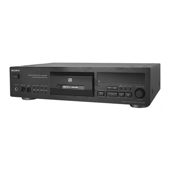
Sony CDP-XB820 Service Manual
Hide thumbs
Also See for CDP-XB820:
- Operating instructions manual (64 pages) ,
- Operating instructions manual (64 pages)
Table of Contents

Related Manuals for Sony CDP-XB820


Summary of Contents for Sony CDP-XB820
- Page 1 CDP-XB820 SERVICE MANUAL AEP Model Model Name Using Similar Mechanism CD Mechanism Type CDM36-14E Base Unit Type BU-14E Optical Pick-up Type KSS-213B/F-NP SPECIFICATIONS – Continued on next page – COMPACT DISC PLAYER MICROFILM...
-
Page 2: Table Of Contents
LINE WITH MARK ! ON THE SCHEMATIC DIAGRAMS AND IN THE PARTS LIST ARE CRITICAL TO SAFE OPERATION. REPLACE THESE COMPONENTS WITH SONY PARTS WHOSE PART NUMBERS APPEAR AS SHOWN IN THIS MANUAL OR IN SUPPLEMENTS PUB- LISHED BY SONY. -
Page 3: Servicing Notes
SECTION 1 SERVICING NOTES HOW TO OPEN THE DISC TRAY WHEN POWER NOTES ON HANDLING THE OPTICAL PICK-UP SWITCH TURNS OFF BLOCK OR BASE UNIT Insert a tapering driver into the aperture of he unit bottom, and The laser diode in the optical pick-up block may suffer electro- turn in the direction of arrow (to OUT direction). - Page 4 CD-TEXT TEST DISC This unit is able to display the test data (character information) written in the CD on its fluorescent indicator tube. The CD-TEXT TEST DISC (TGCS-313:4-989-366-01) is used for checking the display. To check, perform the following procedure. Checking Method: 1.
- Page 5 Table 2: CD-TEXT TEST DISC Recorded Contents and Display (In this unit, some special characters cannot be displayed. This is no a fault.) TRACK Recorded contents Display ! ” # $ % & ´ (21h to 27h)1kHz 0dB L&R + , – . / (28h to 2Fh) 0 1 2 3 4 5 6 7 (30h to 37Fh)
-
Page 6: General
SECTION 2 GENERAL • LOCATION OF CONTROLS 6 789 0 !¡!™ !£ !¢ !∞!§ !¶ !• !ª @º @¡ @™ @£@¢ @∞ 1 U (power) button 2 PLAY MODE button 3 REPEAT button 4 FADER button 5 TIME TEXT button 6 Remote sensor 7 0 button 8 ) button... -
Page 7: Disassembly
SECTION 3 DISASSEMBLY Note: Follow the disassembly procedure in the numerical order given. CASE 2 two screws 3 case (case 3TP2) 2 two screws 1 two screws (case 3TP2) (BV/RING) 2 two screws (case 3TP2) FRONT PANEL SECTION 2 two claws 1 Push the slide cam 3 loading panel ass’y in the direction of the arrow A . - Page 8 MECHANISM DECK (CDM36-14E) 4 two screws 4 two screws (BVTP3 × 8) (BVTP3 × 8) 2 screw (BVTP3 × 8) 5 mechanism deck 3 lug (CDM36-14E) 1 flat wire (23 core) (CN301) MAIN BOARD 2 connector (CN951) 4 two screws 1 flat wire (23 core) (BVTP 3 ×...
-
Page 9: Af Adj Mode
SECTION 4 TEST MODE 4-1. AF ADJ MODE Buttons and Corresponding Button Numbers The following checks can be performed in the AF ADJ mode, which Button Button Number or Display is set by connecting the TP2 (AF ADJ : JW96) terminal on MAIN LANGUAGE board to the Ground and turning on the power. -
Page 10: Adj Mode
4-2. ADJ MODE [ MAIN BOARD ] – Conductor Side – The following operations are performed in the ADJ mode, which is set by connecting the TP1 (ADJ : JW98) terminal to the Ground JW096 and turning on the power. IC930 •... -
Page 11: Aging Mode
4-4. AGING MODE 1. How to Enter AGING Mode Aging method 1 (When using the aging mode remote controller (J-2501-123-A)): 1) Pess the U button and turn ON the power. 2) Set the disc on the tray. [AGING START] 3) Press the button of the aging remote control- ler. -
Page 12: Electrical Block Checking
SECTION 5 ELECTRICAL BLOCK CHECKING Note: A clear RF signal waveform means that the shape “≈” can be clearly Note: distinguished at the center of the waveform. 1. CD Block is basically designed to operate without adjustment. There- fore, check each item in order given. 2. - Page 13 RF PLL Free-run Frequency Check 6. Check the level B of the oscilliscope's waveform and the A (DC voltage) of the center of the Traverse waveform. Procedure : Confirm the following : 1. Connect frequency counter to test point (MNT1) with lead wire. A/B x 100 = less than ±...
-
Page 14: Diagrams
SECTION 6 DIAGRAMS 6-1. IC PIN FUNCTION DESCRIPTION • DISP BOARD IC801 CXP82832-009Q (SYSTEM CONTROLLER/FL DRIVER) Pin No. Pin Name Function 1, 2 13G, 14G Grid drive signal output to the fluorescent indicator tube (FL801) “H”: goes on — Not used (fixed at “H”) —... - Page 15 Pin No. Pin Name Function MODEL.SEL2 Destination setting terminal (fixed at “L”) AVSS — Ground terminal (for A/D converter) System reset signal input from the reset signal generator (IC930) “L”: reset For several hundreds msec. after the power supply rises, “L” is input, then it changes to “H” EXTAL Main system clock input terminal (8 MHz) XTAL...
-
Page 16: Note For Printed Wiring Boards And Schematic Diagrams
6-2. NOTE FOR PRINTED WIRING BOARDS AND SCHEMATIC DIAGRAMS Note on Schematic Diagram: Note on Printed Wiring Boards: • X : parts extracted from the component side. • All capacitors are in µF unless otherwise noted. pF: µµF • 50 WV or less are not indicated except for electrolytics : Through hole. - Page 17 • Circuit Boards Location TRANS board BD board AC SW board LOADING board SLED board HP board VC SELECT board MAIN board KEY board SPINDLE board DISP board – 17 –...
- Page 18 • Waveforms – BD Board – 1 IC103 !§ (RFO) (PLAY MODE) 6 IC101 0 (WFCK) 2 V/DIV, 100 µs/DIV 500 mV/DIV, 1 µs/DIV 1.2 ± 0.2 Vp-p 5.8 Vp-p 136 µ s 2 IC101 $¡ (TE) (PLAY MODE) 200 mV/DIV, 1 µs/DIV 7 IC101!™...
-
Page 19: Printed Wiring Board – Bd Section
CDP-XB820 6-3. PRINTED WIRING BOARD – BD Section – • See page 17 for Circuit Boards Location. (Page 23) (Page 23) • Semiconductor Location (Page 25) Ref. No. Location D101 IC101 IC102 IC103 Q101 Q102 – 19 – – 20 –... -
Page 20: Schematic Diagram - Bd Section
CDP-XB820 6-4. SCHEMATIC DIAGRAM – BD Section – • See page 18 for Waveforms. • See page 39 and 40 for IC Block Diagrams. (Page 24) (Page 24) (Page 27) – 21 – – 22 –... -
Page 21: Printed Wiring Boards - Optical Pick-Up/Motor Section
CDP-XB820 6-5. PRINTED WIRING BOARDS – OPTICAL PICK-UP / MOTOR Section – 6-6. SCHEMATIC DIAGRAM – OPTICAL PICK-UP / MOTOR Section – • See page 17 for Circuit Boards Location. (Page 20) (Page 23) (Page 22) (Page 20) (Page 22) -
Page 22: Printed Wiring Board - Main Section
CDP-XB820 6-7. PRINTED WIRING BOARD – MAIN Section – • See page 17 for Circuit Boards Location. (Page 36) (Page 31) (Page 20) (Page 26) • Semiconductor Location Ref. No. Location Ref. No. Location Ref. No. Location D301 IC303 Q301... -
Page 23: Schematic Diagram – Main Section (1/2)
CDP-XB820 6-8. SCHEMATIC DIAGRAM – MAIN Section (1/2) – • See page 18 for Waveform. • See page 41 for IC Block Diagrams. (Page 21) (Page 29) (Page 38) – 27 – – 28 –... -
Page 24: Schematic Diagram - Main Section (1/2)
CDP-XB820 6-9. SCHEMATIC DIAGRAM – MAIN Section (2/2) – (Page 33) (Page 28) – 29 – – 30 –... -
Page 25: Printed Wiring Boards - Power Section
CDP-XB820 6-10. PRINTED WIRING BOARDS – POWER Section – • See page 17 for Circuit Boards Location. (Page 31) (Page 25) (Page 32) – 31 – – 32 –... -
Page 26: Schematic Diagram - Power Section
CDP-XB820 6-11. SCHEMATIC DIAGRAM – POWER Section – (Page 30) The components identified by mark ! or dotted line with mark ! are critical for safety. Replace only with part number specified. – 33 – – 34 –... -
Page 27: Printed Wiring Boards - Panel Section
CDP-XB820 6-12. PRINTED WIRING BOARDS – PANEL Section – • See page 17 for Circuit Boards Location. (Page 35) (Page 25) (Page 36) – 35 – – 36 –... -
Page 28: Schematic Diagram - Panel Section
CDP-XB820 6-13. SCHEMATIC DIAGRAM – PANEL Section – • See page 18 for Waveform. (Page 27) – 37 – – 38 –... - Page 29 • IC Block Diagrams – BD BOARD – IC101 CDX2585Q 71 70 62 61 67 66 65 64 63 Digital VPCO DVDD0 Clock V16M Generator XRST VCTL MUTE Interface BIAS Error AVDD1 Corrector DATA XLAT CLOCK FILI Digital Interface Sub Code FILO demodurator Processor...
- Page 30 IC103 CXA2568M-T6 HOLD APC PD AMP LC/PD APC LD AMP – LD ON – – – HOLD SW AGC CONT AGC VTH 50µA RF BOT – – – – RFTC RF SUMMING AMP RF EQ AMP RF I RF O –...
-
Page 31: Main Board
– MAIN Board – IC301 CXD8735N INVO INVI BCKI TEST OVERFLOW DETECTER DATA1 128FsO FIR1 FIR2 FIR3 LRCKI DINIT FIR4 INIT OVFLAG MUTEL OVERFLOW DETECTER SHIFT MUTER FIR1 FIR2 FIR3 LATCH FIR4 SYSM 64FSI MCKIN 3rd order X0.75 NOISE L.I.P DVSS1 SHAPER DITHER... -
Page 32: Exploded Views
X-4949-457-1 PANEL ASSY, LOADING 4-997-202-11 BASE (M1), PANEL 4-950-189-01 KNOB (A) (VOL) * 19 A-4699-984-A DISP BOARD, COMPLETE 4-942-568-41 EMBLEM (NO.5), SONY 1-773-216-11 WIRE (FLAT TYPE) (25 CORE) 4-997-199-21 PANEL, FRONT 4-997-213-01 BUTTON (F.R) (0, )) 4-997-200-01 BASE (L), PANEL... - Page 33 (2) CHASSIS SECTION T901 CDM36-14E supplied supplied supplied supplied The components identified by mark ! or dotted line with mark ! are critical for safety. Replace only with part number specified. Ref. No. Part No. Description Remark Ref. No. Part No. Description Remark 4-984-485-01 CUSHION (FOOT)
- Page 34 (3) MECHANISM DECK SECTION (CDM36-14E) supplied BU-14E supplied not supplied M903 not supplied not supplied supplied supplied not supplied Ref. No. Part No. Description Remark Ref. No. Part No. Description Remark 1-452-820-11 MAGNET (ASSY) 4-977-896-01 PULLEY * 102 4-977-902-01 PANEL (DRAWER) 4-968-905-01 BELT (CDM) * 103 4-977-894-01 HOLDER (AP)
- Page 35 (4) BASE UNIT SECTION M902 (BU-14E) supplied supplied supplied supplied M901 The components identified by mark ! or dotted line with mark ! are critical for safety. Replace only with part number specified. Ref. No. Part No. Description Remark Ref. No. Part No.
-
Page 36: Electrical Parts List
SECTION 8 AC SW ELECTRICAL PARTS LIST NOTE: • Due to standardization, replacements in the • Items marked “*” are not stocked since they The components identified by mark ! or dotted line with mark are seldom required for routine service. parts list may be different from the parts speci- ! are critical for safety. - Page 37 DISP Ref. No. Part No. Description Remark Ref. No. Part No. Description Remark < RESISTOR > R173 1-216-073-00 METAL CHIP 1/10W R174 1-216-073-00 METAL CHIP 1/10W R101 1-216-077-00 METAL CHIP 1/10W R175 1-216-073-00 METAL CHIP 1/10W R102 1-216-097-00 RES,CHIP 100K 1/10W R176 1-216-073-00 METAL CHIP...
- Page 38 DISP LOADING MAIN Ref. No. Part No. Description Remark Ref. No. Part No. Description Remark R821 1-249-441-11 CARBON 100K 1/4W R857 1-249-429-11 CARBON 1/4W R822 1-247-807-31 CARBON 1/4W R823 1-247-807-31 CARBON 1/4W < SWITCH > R824 1-249-417-11 CARBON 1/4W S851 1-554-303-21 SWITCH, TACTILE (LANGUAGE) R825 1-249-429-11 CARBON...
- Page 39 MAIN Ref. No. Part No. Description Remark Ref. No. Part No. Description Remark C381 1-161-494-00 CERAMIC 0.022uF EB602 1-537-770-21 TERMINAL BOARD, GROUND C391 1-124-994-11 ELECT 100uF C392 1-164-159-21 CERAMIC 0.1uF < IC > C394 1-164-159-21 CERAMIC 0.1uF C404 1-126-023-11 ELECT 100uF IC301 8-759-527-07 IC CXD8735N...
- Page 40 MAIN SLED SPINDLE TRANS Ref. No. Part No. Description Remark Ref. No. Part No. Description Remark R555 1-249-402-11 CARBON 1/4W R316 1-249-419-11 CARBON 1.5K 1/4W R902 1-249-421-11 CARBON 2.2K 1/4W R317 1-249-441-11 CARBON 100K 1/4W R903 1-249-436-11 CARBON 1/4W R318 1-249-429-11 CARBON 1/4W R319...
- Page 41 TRANS VC SELECT Ref. No. Part No. Description Remark Ref. No. Part No. Description Remark C992 1-164-159-21 CERAMIC 0.1uF MISCELLANEOUS C995 1-136-165-00 FILM 0.1uF ************** C996 1-136-165-00 FILM 0.1uF C998 1-136-850-11 FILM 0.1uF 1-773-216-11 WIRE (FLAT TYPE) (25 CORE) 1-783-699-11 WIRE (FLAT TYPE) (23 CORE) <...
- Page 42 CDP-XB820 Sony Corporation 98F057541-1 Printed in Hungary © 1998. 6 9-922-850-11 Home A&V Products Company Published by Quality Assurance Dept. – 52 – (Shibaura)