Sign In
Upload
Manuals
Brands
YOKOGAWA Manuals
Transmitter
vigilantplant EXA ISC202G
YOKOGAWA vigilantplant EXA ISC202G Manuals
Manuals and User Guides for YOKOGAWA vigilantplant EXA ISC202G. We have
1
YOKOGAWA vigilantplant EXA ISC202G manual available for free PDF download: User Manual
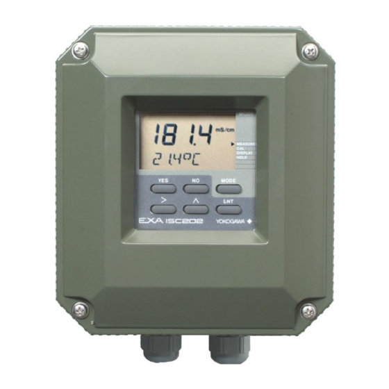
YOKOGAWA vigilantplant EXA ISC202G User Manual (121 pages)
2-wire Inductive Conductivity Transmitter
Brand:
YOKOGAWA
| Category:
Transmitter
| Size: 3.53 MB
Table of Contents
User's Manual
2
Table of Contents
2
Preface
5
Introduction and General Description
9
Instrument Check
9
Application
11
General Specifications
13
Specifications
13
Ma K) Sensor Diagnostics/Ma K) Sensor Diagnostics
14
Model and Suffix Codes
18
Control Drawing ISC202S Ma HART ® Specification (Iecex)
19
Control Drawing ISC202S Ma HART ® Specification (ATEX)
20
(FM Intrinsically Safe Design)
21
Control Drawing ISC202S Ma HART ® Specification
21
Control Drawing of ISC202S Ma HART ® Specification (CSA)
23
Control Drawing of ISC202S FF/PB Specification (Iecex)
24
Control Drawing of ISC202S FF/PB Specification (ATEX)
25
Control Drawing of ISC202S FF/PB Specification (FM Intrinsically Safe Entity)
26
Control Drawing of ISC202S FF/PB Specification (FM Intrinsically Safe FISCO)
28
Control Drawing of ISC202S FF/PB Specification (FM Non-Incendive Entity)
30
Control Drawing of ISC202S FF/PB Specification (FM Non-Incendive FNICO)
31
Control Drawing of ISC202S FF/PB Specification (CSA)
32
Installation and Dimensions
33
Installation and Wiring
33
Installation Site
33
Mounting Methods
33
Cables, Terminals and Glands
34
Preparation
34
Additional Precautions for Installations in Hazardous Areas
35
General Precautions
35
Installation In: Hazardous Area-Non-Incendive
35
Wiring of Sensors
35
Connection of the Power Supply
36
General Precautions
36
Sensor Wiring
36
Switching the Instrument on
36
Wiring of the Power Supply
36
Other Sensor Systems
37
Sensor Cable Connections Using Junction Box (BA10) and Extension Cable (WF10)
37
Operation; Display Functions and Setting
39
Operator Interface
39
Explanation of Operating Keys
40
Display Examples
41
Passcode Protection
41
Setting Passcodes
41
Display Functions
42
Introduction
43
Maintenance Mode
43
Parameter Setting
43
Manual Calibration to Determine the Cell Constant (C.C.)
44
Second Line Display. Referring to the First Compensated Conductivity
45
Second Line Display. Referring to the Second Compensated Conductivity
46
Commissioning Mode
48
Hold
48
Temperature Compensation
51
Temperature Compensation for First Conductivity Value
53
Temperature Compensation for Second Conductivity Value
54
5-3.Service Codes
55
Parameter Specific Functions
55
Temperature Measuring Functions
55
Temperature Compensation Functions
56
Keys
57
Ma Output Functions
59
User Interface
60
Communication Setup
61
General
61
Calibration
63
When Is Calibration Necessary
63
Calibration Procedure
64
Maintenance
65
Periodic Maintenance for the EXA 202 Transmitter
65
Periodic Maintenance of the Sensor
65
Checking During Operation
66
Introduction
66
Self Diagnostics of the Conductivity Sensor
66
Self Diagnostics of the Electronics
66
Self Diagnostics of the Temperature Sensor
66
Troubleshooting
66
Error Messages and Explanation
67
Spare Parts
68
User Entered Matrix Data (Code 23 to 28)
69
User Setting for Non-Linear Output Table (Code 31, 35)
69
Matrix Data Table (User Selectable in Code 22)
70
Coded Service Settings (Default)
71
Configuration Checklist for ISC202
71
Device Description (DD) Menu Structure
72
PH201G*B Dedicated Distributor
73
Preface
73
Wiring Diagrams
73
BA20 Junction Terminal Box
75
WF10J Extension Cable
76
Quick Reference for Parameter Setting
77
Calibration with Solution of Known Conductivity
78
Selecting Items for Display
78
Settings Performed in Maintenance Mode
78
Commissioning Mode Settings
79
Output Range Setting
79
Setting Hold Functions
79
Correcting Zero Offset Error by Calibration in Air (Air Set)
80
Temperature Compensation
80
Actual Setting Examples
81
Setting Output in Terms of Concentration
82
Key Operation Procedure Examples
87
Installation Factor Adjustment
91
Appendix 3 QUALITY INSPECTION
93
ISC202G 2-Wire Inductive Conductivity Transmitter
93
ISC202S 2-Wire Inductive Conductivity Transmitter
98
ISC202G, ISC202S 2-Wire Inductive Conductivity Transmitter (Fieldbus Communication)
103
ISC202G, ISC202S 2-Wire Inductive Conductivity Transmitter (Profibus Communication)
107
Revision Record
115
Abnormal Temperature (Open, Short), Abnormal Conductivity Values (E5/E6 Free Programmable)
119
Algorithm: Selectable as Mentioned below Nacl According to IEC 60746-3
119
Dry Cell, Wiring Problems
119
J) Temperature Compensation: - Sensor Types: Pt1000Ω or 30Kω NTC - Automatic
119
Ma K) Sensor Diagnostics
119
Manual, Calibration Input Pre-Measureds Data (Cell Constant)
119
Matrix: User Selectable/ Configurable. 8 Selectable for Concentrated Solutions, 1 Free Programmable
119
Software Record of Important Events and Diag- Nostic Data
119
To 140 ºC (0 to 280 ºF)
119
Two T.C. Setting Possible between
119
Advertisement
Advertisement
Related Products
YOKOGAWA vigilantplant EXA ISC202S
YOKOGAWA ISC40G(S)
YOKOGAWA ISC450G
YOKOGAWA ISC40PR
YOKOGAWA ISC40FF
YOKOGAWA ISC40FS
YOKOGAWA ISC40FD
YOKOGAWA IS8000
YOKOGAWA Vigilantplant IR200
YOKOGAWA IR800G
YOKOGAWA Categories
Measuring Instruments
Test Equipment
Transmitter
Controller
Media Converter
More YOKOGAWA Manuals
Login
Sign In
OR
Sign in with Facebook
Sign in with Google
Upload manual
Upload from disk
Upload from URL