Sign In
Upload
Manuals
Brands
Xantrex Manuals
Inverter
Trace DR3624
Xantrex Trace DR3624 Manuals
Manuals and User Guides for Xantrex Trace DR3624. We have
3
Xantrex Trace DR3624 manuals available for free PDF download: Installation And Operation Manual, Installation & Operator's Manual, Manual
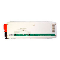
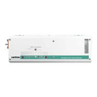
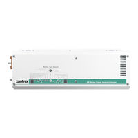
Xantrex Trace DR3624 Installation And Operation Manual (122 pages)
DR Inverter/Charger
Brand:
Xantrex
| Category:
Inverter
| Size: 4.13 MB
Table of Contents
Specifications of the DR Inverter
5
Important Safety Instructions
7
Save These Instructions
7
Explosive Gas Precautions
8
Precautions When Working with Batteries
9
Table of Contents
11
1 Introduction
19
Introduction
19
Features
20
AC Side
21
Figure 1-1 Front Panel Features
21
Figure 1-2 AC Side of the DR Inverter
21
DC Side
22
Optional Equipment
22
Remote Control (RC8)
22
Stacking Interface (DRI)
22
Conduit Box (DRCB)
22
Unpacking and Inspection
22
Figure 1-3 DC Side of the DR Inverter
22
Model Identification and Numbering Conventions
23
Figure 1-4 Product Identification
23
Table 1-1 Model Identification and Numbering Conventions
23
Table 1-2 Letter Suffix Code Definitions
24
Installation
25
Pre-Installation Planning
26
Location
26
Mounting
27
Ventilation
27
Tools Required
27
Hardware / Materials Required
28
Wiring Considerations
28
DC Terminal Connections
28
Grounding Considerations
28
AC Grounding
28
DC Grounding
28
Wire Routing
29
Electrical Panels and Circuit Breaker Requirements
29
AC Distribution Panel (Sub-Panel)
29
DC Disconnect
29
Battery Considerations
29
Battery Location
30
Battery Temperature
30
Basic Configurations
30
Figure 2-1 On-Grid Basic Configuration (Utility Backup)
31
Figure 2-2 Off-Grid Configuration (Generator Only)
31
Figure 2-3 On-Grid Configuration - with Renewable Energy Sources
32
Figure 2-4 Off-Grid Configuration - with Renewable Energy Sources
33
Generators
34
Figure 2-5 Charge Rate Versus Peak AC Voltage
34
Table 2-1 Peak Input Filtrate Versus Charging Current
34
Inverter Mounting
35
Figure 2-6 Dimensions (Not to Scale)
35
Figure 2-7 Suggested Mounting Method
36
Figure 2-8 Mounting on Plywood
36
DC Wiring
37
DC Circuit Grounding
37
General DC Grounding Requirements
37
Table 2-2 Safety Ground Conductor Size
37
Figure 2-9 DC Grounding
38
Batteries
39
Battery Types
39
Battery Bank Sizing
39
Battery Configuration
39
Battery Cable Sizing
40
Table 2-3 Minimum Recommended Battery Cable Size Versus Length
40
DC Disconnect and Over-Current Protection
41
Table 2-4 Battery Cable to Maximum Breaker/Fuse Size
41
Battery Cable Connections
42
Figure 2-10 Battery Cable Connections
42
Connecting the Battery Bank to the Inverter
43
Figure 2-11 DC Terminals on the DR Inverter
43
Figure 2-12 Connecting the Battery Bank to the DR Inverter/Charger
44
Figure 2-13 Battery Temperature Sensor (BTS) RJ11 Jack Location
45
Figure 2-14 Connecting the BTS to the DR Inverter
45
Installing a Battery Temperature Sensor
45
AC Wiring
46
AC Distribution Panel (Sub-Panel) Mounting and Conduit Installation
46
Accessing the AC Terminals
46
Figure 2-15 AC Side Cover Panels
47
Table 2-5 Minimum Recommended Wire Size, Torque Values (Input and Output)
47
Figure 2-16 AC Terminals for AC Input to the Inverter
48
AC Output Wiring to the AC Distribution Panel (Sub-Panel)
49
Figure 2-17 AC Terminals for AC Output to the Sub-Panel
49
AC Input Wiring - On-Grid Applications
50
Figure 2-18 AC Wiring- On-Grid Application
50
AC Input Wiring Using a Generator in an On-Grid Application
51
Figure 2-19 AC Wiring Using a Generator - On-Grid Application
51
AC Input Wiring - Off-Grid Applications Using a 120 Vac Generator
52
Figure 2-20 AC Wiring Using a 120 Vac Generator - Off-Grid Application
52
Figure 2-21 AC Wiring Using a 240 Vac Generator with 120 Vac Loads Only- Off-Grid Application
53
Series Stacking (120 Vac/60 Hz Models Only)
54
Figure 2-22 AC Wiring for Dual-Inverters - On-Grid Application (120 Vac Models Only)
55
Figure 2-23 Wiring for Dual-Inverters - On-Grid Application (120 Vac Models Only)
56
Operation
57
Front Panel Controls and Indicators
58
POWER ON/OFF Switch
58
Figure 3-1 Front Panel Controls and Indicators
58
Ports
59
BATTERY SENSE Port
59
COM Port
59
Remote Controls (RC8/RC4)
59
Stacking Interface
60
Controls
60
Battery Type Selector
60
Figure 3-2 Battery Type Selector Adjustment
60
Table 3-1 Battery Type Selector Switch Settings
61
SEARCH MODE WATTS Potentiometer
62
Battery Charger Rate
63
Figure 3-3 Battery Type Selector Adjustment
63
Figure 3-4 Battery Charger Rate Potentiometer (DR1512 Values Used)
64
Over Discharge Protection/Ac Transfer Voltage
64
Table 3-2 Approximate Charge Rate Setting/Amperage
64
Figure 3-5 ODP Enabled/Disabled Positions
65
Figure 3-6 Automatically Calculated Discharge Cutoff Voltage Per Cell
65
Over Discharge Protection (ODP)
65
AC Transfer Voltage
66
Table 3-3 ODP/AC Transfer Voltage
66
Figure 3-7 ODP Enabled/Disabled Positions
67
Figure 3-8 Typical Setting for most Utility Application
67
Battery Capacity
68
Figure 3-10 Battery Capacity Potentiometer (Old)
68
Figure 3-9 Battery Capacity Potentiometer (New)
68
LED Indicators
69
Inverter Mode LED - Green
69
Over Temp / Overload LED - Red / Green (Error Condition)
69
Battery High/Battery Low LED - Red/Green (Error Condition)
69
Figure 3-11 LED Indicators
69
Charger LED - Orange / Green
70
Audible Indicator (Internal)
70
Circuit Breakers
71
Figure 3-12 AC Pass-Through and Charger AC Input Circuit Breakers
71
Table 3-4 AC Pass-Through Circuit Breakers
71
Table 3-5 Battery Charger Circuit Breakers
71
Start-Up
72
Figure 3-13 Startup Items
72
Charger Mode
73
3-Stage Charging Process
73
Equalize Charging
74
Figure 3-14 Charger Controls and Indicators
74
Figure 3-15 Equalize Positions on Battery Type Selector Switch
75
Figure 3-16 Equalize 1 Battery Charger Rate Potentiometer (Position "1")
76
Figure 3-17 Equalize 2 Battery Capacity Rate Potentiometer (Position "0")
76
Troubleshooting
77
Troubleshooting the DR Inverter
78
Table 4-1 Troubleshooting the DR Inverter
78
Problem Loads
79
Ceiling Fans
79
Cell Phones
79
Computers and Sensitive Electronics
79
Consumer Electronics
79
Clocks
80
Decreasing Loads
80
Dimmer Switches
80
Fluorescent Lights
80
Heavy Loads
80
Microwave Ovens
80
Printers
81
Rechargeable Devices
81
Undersized Loads
81
Specifications
83
A Specifications
84
Specifications of the DR Inverter
84
Table A-4 Environmental Specifications for the DR Inverter/Charger
89
Battery Information
91
Introduction
92
Battery Types
92
Deep-Cycle Flooded Lead Acid (FLA
92
Sealed Batteries (Gel and AGM
93
Nicad and Nife Batteries
93
Understanding Battery Capacity Ratings
94
Battery Bank Sizing
94
Understanding Amp-Hour Requirements
95
Calculating Amp Hours
95
Amp Hour Example Worksheet
96
Table B-1 Determining Average Daily Load in Amp-Hours
96
Battery Bank Size Worksheet
97
Table B-2 Determining Battery Bank Size
97
Table B-3 Typical Appliance Wattage
97
Battery Configurations
98
Wiring Batteries in Series
98
Figure B-1 6-Volt Battery Wiring - "Series" Configuration
98
Wiring Batteries in Parallel
99
Figure B-2 12-Volt Battery Wiring - "Series" Configuration
99
Figure B-3 Battery Wiring in Parallel
99
Wiring Batteries in Series-Parallel
100
Battery Connections for Stacked Inverters
102
Figure B-7 Example of Battery Connections for Stacked Inverters (24 VDC Shown
102
Battery Maintenance
103
Battery Charging
103
Table B-4 Variances in Charging Voltage Based on Battery Temperature
104
Table B-5 Temperature Compensation Calculation
104
Equalization Charging
105
General Maintenance
106
Table B-6 Battery State-Of-Charge
107
C Multi-Wire Branch Circuit Wiring
109
Multi-Wire Branch Circuits
110
Figure C-1 Conventional Home-Type Wiring
110
Figure C-2 Multi-Wire Branch Circuit Wiring and Current Flow
111
Figure C-3 120 Vac Inverter Incorrectly Wired in a Multi-Wire Branch Circuit
111
Identifying Multi-Wire Branch Circuits
112
Figure C-4 Multi-Wire Branch Circuit Wiring
112
Correcting Multi-Wire Branch Circuit Wiring
113
Figure C-5 Using a Step-Down Autotransformer in Multi-Wire Branch Circuit Wiring
114
Warranty and Return Information
115
Return Material Authorization Policy
117
Return Procedure
117
Out of Warranty Service
117
Information about Your System
118
Index
119
Advertisement
Xantrex Trace DR3624 Installation & Operator's Manual (84 pages)
Inverter/Charger
Brand:
Xantrex
| Category:
Battery Charger
| Size: 10.35 MB
Table of Contents
Table of Contents
3
Description Page
4
1.0 Introduction
9
Unpacking and Inspection
10
Model Identification and Numbering Conventions
11
Certification
12
2.0 Installation
13
Features
13
Modified Sine Wave Power
13
Battery Charger/Ac Transfer Relay
13
Simplicity
13
High Efficiency
13
Low Power Consumption
13
Options
13
Rc4/Rc8
13
Dri
13
Pre-Installation
14
Location
14
Mounting
14
Ventilation
14
Tools Required
15
Hardware/Materials Required
15
Wiring
15
AC Connections
15
DC Connections
15
Grounding
15
AC Grounding
15
DC Grounding
15
Batteries
16
Battery Location
16
Battery Temperature
16
Main Service Panel
18
Sub-Panel
18
AC Circuit Breakers
18
DC Disconnect
18
Wire Routing
18
Inverter Mounting
19
Wiring
21
DC Wiring (Batteries)
21
Battery Cable Sizing
21
DC Disconnect and Over-Current Protection
22
Battery Cable Connections
23
Battery Bank Sizing
24
Battery Types
24
Battery Configuration
24
Series
24
Parallel
24
Series-Parallel
24
Description
46
OPERATION (Continued)
46
(Continued) Battery Capacity
46
Inverter Mode LED - Green
48
Start-Up
57
Charger Mode
58
Equalize Charging
60
4.0 Troubleshooting
61
5.0 Appendix
63
Batteries
63
Selection of a Battery Type
63
Battery Bank Sizing
65
Typical Appliance Wattages
68
Battery Care and Maintenance
69
Problem Loads
72
Multiwire Branch Circuits
74
Limited Warranty
77
7.0 Service Information
79
8.0 Specifications
80
Xantrex Trace DR3624 Manual (84 pages)
Inverter/Charger
Brand:
Xantrex
| Category:
Inverter
| Size: 10.36 MB
Table of Contents
Not Recommended
21
Main Panel
37
Sub Panel
37
Inverter Type
38
Discharge Protection
61
Inverter Mode Led
61
Charger Led
62
System Voltage
71
Advertisement
Advertisement
Related Products
Xantrex DR1512W
Xantrex DR1512E
Xantrex DR1524E
Xantrex DR1524W
Xantrex Trace DR1512
Xantrex Trace DR2412
Xantrex Trace DR2424
Xantrex DR2424E
Xantrex Trace DR1524
Xantrex DR - REV A
Xantrex Categories
Inverter
Power Supply
Battery Charger
Power Pack
Controller
More Xantrex Manuals
Login
Sign In
OR
Sign in with Facebook
Sign in with Google
Upload manual
Upload from disk
Upload from URL