Sign In
Upload
Manuals
Brands
Winbond Manuals
I/O Systems
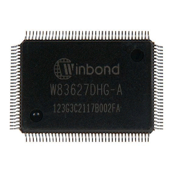
W83627DHG
Winbond W83627DHG Manuals
Manuals and User Guides for Winbond W83627DHG. We have
1
Winbond W83627DHG manual available for free PDF download: Manual
Winbond W83627DHG Manual (268 pages)
Low Pin Count interface
Brand:
Winbond
| Category:
I/O Systems
| Size: 1.8 MB
Table of Contents
Table of Contents
6
1 General Description
13
2 Features
14
3 Block Diagram
17
4 Pin Layout
18
5 Pin Description
20
LPC Interface
21
FDC Interface
21
Multi-Mode Parallel Port
22
Serial Port & Infrared Port Interface
24
KBC Interface
26
Serial Peripheral Interface
26
Hardware Monitor Interface
27
PECI Interface
29
SST Interface
29
Advanced Configuration and Power Interface
29
General Purpose I/O Port
30
Smbus Interface
30
GPIO Power Source
30
GPIO-2 Interface
31
GPIO-3 Interface
32
GPIO-4 Interface
32
GPIO-5 Interface
33
GPIO-6 Interface
33
GPIO-4 with WDTO# / SUSLED Multi-Function
34
Particular ACPI Function Pins - both for UBE and UBF Version Only
34
Power Pins
35
6 Configuration Register Access Protocol
36
Configuration Sequence
37
Enter the Extended Function Mode
37
Configure the Configuration Registers
37
Exit the Extended Function Mode
38
Software Programming Example
38
7 Hardware Monitor
40
General Description
40
Access Interfaces
40
LPC Interface
41
C Interface
42
Analog Inputs
43
Voltages over 2.048 V or Less than 0 V
43
Voltage Detection
44
Temperature Sensing
44
SST Command Summary
46
Command Summary
46
Combination Sensor Data Format
47
Peci
48
Fan Speed Measurement and Control
51
Fan Speed Measurement
51
Fan Speed Control
52
SMART FAN TM Control
53
Interrupt Detection
62
SMI# Interrupt Mode
62
OVT# Interrupt Mode
65
Caseopen Detection
66
BEEP Alarm Function
67
8 Hardware Monitor Register Set
68
Address Port (Port X5H)
68
Data Port (Port X6H)
68
SYSFANOUT PWM Output Frequency Configuration Register - Index 00H (Bank 0)
69
SYSFANOUT Output Value Select Register - Index 01H (Bank 0)
69
CPUFANOUT0 PWM Output Frequency Configuration Register - Index 02H (Bank 0)
70
CPUFANOUT0 Output Value Select Register - Index 03H (Bank 0)
71
FAN Configuration Register I - Index 04H (Bank 0)
71
SYSTIN Target Temperature Register/ SYSFANIN Target Speed Register - Index 05H
72
CPUTIN Target Temperature Register/ CPUFANIN0 Target Speed Register - Index 06H (Bank 0)
73
Tolerance of Target Temperature or Target Speed Register - Index 07H (Bank 0)
73
SYSFANOUT Stop Value Register - Index 08H (Bank 0)
74
CPUFANOUT0 Stop Value Register - Index 09H (Bank 0)
74
SYSFANOUT Start-Up Value Register - Index 0Ah (Bank 0)
75
CPUFANOUT0 Start-Up Value Register - Index 0Bh (Bank 0)
75
SYSFANOUT Stop Time Register - Index 0Ch (Bank 0)
76
CPUFANOUT0 Stop Time Register - Index 0Dh (Bank 0)
76
Fan Output Step down Time Register - Index 0Eh (Bank 0)
77
Fan Output Step up Time Register - Index 0Fh (Bank 0)
77
AUXFANOUT PWM Output Frequency Configuration Register - Index 10H (Bank 0)
78
AUXFANOUT Output Value Select Register - Index 11H (Bank 0)
78
FAN Configuration Register II - Index 12H (Bank 0)
79
AUXTIN Target Temperature Register/ AUXFANIN0 Target Speed Register - Index 13H
80
(Bank 0)
80
Tolerance of Target Temperature or Target Speed Register - Index 14H (Bank 0)
81
AUXFANOUT Stop Value Register - Index 15H (Bank 0)
81
AUXFANOUT Start-Up Value Register - Index 16H (Bank 0)
82
AUXFANOUT Stop Time Register - Index 17H (Bank 0)
82
OVT# Configuration Register - Index 18H (Bank 0)
83
Reserved Registers - Index 19H ~ 1Fh (Bank 0)
83
Value RAM ⎯ Index 20H ~ 3Fh (Bank 0)
83
Configuration Register - Index 40H (Bank 0)
85
Interrupt Status Register 1 - Index 41H (Bank 0)
85
Interrupt Status Register 2 - Index 42H (Bank 0)
86
SMI# Mask Register 1 - Index 43H (Bank 0)
87
SMI# Mask Register 2 - Index 44H (Bank 0)
87
Reserved Register - Index 45H (Bank 0)
87
SMI# Mask Register 3 - Index 46H (Bank 0)
87
Fan Divisor Register I - Index 47H (Bank 0)
88
Serial Bus Address Register - Index 48H (Bank 0)
89
CPUFANOUT0/AUXFANOUT Monitor Temperature Source Select Register - Index 49H (Bank 0)
89
CPUFANOUT1 Monitor Temperature Source Select Register - Index 4Ah (Bank 0)
90
Fan Divisor Register II - Index 4Bh (Bank 0)
91
SMI#/OVT# Control Register - Index 4Ch (Bank 0)
91
FAN IN/OUT Control Register - Index 4Dh (Bank 0)
92
Register 50H ~ 5Fh Bank Select Register - Index 4Eh (Bank 0)
93
Winbond Vendor ID Register - Index 4Fh (Bank 0)
93
Reserved Register - Index 50H ~ 55H (Bank 0)
94
BEEP Control Register 1 - Index 56H (Bank 0)
94
BEEP Control Register 2 - Index 57H (Bank 0)
95
Chip ID - Index 58H (Bank 0)
96
Diode Selection Register - Index 59H (Bank 0)
96
Reserved Register - Index 5Ah ~ 5Ch (Bank 0)
97
VBAT Monitor Control Register - Index 5Dh (Bank 0)
97
Critical Temperature and Current Mode Enable Register - Index 5Eh (Bank 0)
98
Reserved Register - Index 5Fh (Bank 0)
99
CPUFANOUT1 PWM Output Frequency Configuration Register - Index 60H (Bank 0)
99
CPUFANOUT1 Output Value Select Register - Index 61H (Bank 0)
99
FAN Configuration Register III - Index 62H (Bank 0)
100
Target Temperature Register/Cpufanin1 Target Speed Register - Index 63H (Bank 0)
101
CPUFANOUT1 Stop Value Register - Index 64H (Bank 0)
101
CPUFANOUT1 Start-Up Value Register - Index 65H (Bank 0)
102
CPUFANOUT1 Stop Time Register - Index 66H (Bank 0)
102
CPUFANOUT0 Maximum Output Value Register - Index 67H (Bank 0)
103
CPUFANOUT0 Output Step Value Register - Index 68H (Bank 0)
103
CPUFANOUT1 Maximum Output Value Register - Index 69H (Bank 0)
104
CPUFANOUT1 Output Step Value Register - Index 6Ah (Bank 0)
104
SYSFANOUT Critical Temperature Register - Index 6Bh (Bank 0)
105
CPUFANOUT0 Critical Temperature Register - Index 6Ch (Bank 0)
105
AUXFANOUT Critical Temperature Register - Index 6Dh (Bank 0)
105
CPUFANOUT1 Critical Temperature Register - Index 6Eh (Bank 0)
106
CPUTIN Temperature Sensor Temperature (High Byte) Register - Index 50H (Bank 1)
106
CPUTIN Temperature Sensor Temperature (Low Byte) Register - Index 51H (Bank 1)
107
CPUTIN Temperature Sensor Configuration Register - Index 52H (Bank 1)
107
CPUTIN Temperature Sensor Hysteresis (High Byte) Register - Index 53H (Bank 1)
108
CPUTIN Temperature Sensor Hysteresis (Low Byte) Register - Index 54H (Bank 1)
108
CPUTIN Temperature Sensor Over-Temperature (High Byte) Register - Index 55H (Bank1)97 8.76 CPUTIN Temperature Sensor Over-Temperature (Low Byte) Register - Index 56H (Bank 1)
109
AUXTIN Temperature Sensor Temperature (High Byte) Register - Index 50H (Bank 2)
110
AUXTIN Temperature Sensor Temperature (Low Byte) Register - Index 51H (Bank 2)
110
AUXTIN Temperature Sensor Configuration Register - Index 52H (Bank 2)
110
AUXTIN Temperature Sensor Hysteresis (High Byte) Register - Index 53H (Bank 2)
111
AUXTIN Temperature Sensor Hysteresis (Low Byte) Register - Index 54H (Bank 2)
111
AUXTIN Temperature Sensor Over-Temperature (High Byte) Register - Index 55H (Bank 2)
112
AUXTIN Temperature Sensor Over-Temperature (Low Byte) Register - Index 56H (Bank 2)
112
Interrupt Status Register 3 - Index 50H (Bank 4)
113
SMI# Mask Register 4 - Index 51H (Bank 4)
114
Reserved Register - Index 52H (Bank 4)
114
BEEP Control Register 3 - Index 53H (Bank 4)
114
SYSTIN Temperature Sensor Offset Register - Index 54H (Bank 4)
115
CPUTIN Temperature Sensor Offset Register - Index 55H (Bank 4)
115
AUXTIN Temperature Sensor Offset Register - Index 56H (Bank 4)
116
Reserved Register - Index 57H-58H (Bank 4)
116
Real Time Hardware Status Register I - Index 59H (Bank 4)
116
Real Time Hardware Status Register II - Index 5Ah (Bank 4)
117
Real Time Hardware Status Register III - Index 5Bh (Bank 4)
118
Reserved Register - Index 5Ch ~ 5Fh (Bank 4)
119
Value RAM 2 ⎯ Index 50H-59H (Bank 5)
119
Reserved Register - Index 50H ~ 57H (Bank 6)
119
9 Serial Peripheral Interface
120
Using the SPI Interface Via the LPC
120
10 Floppy Disk Controller
123
FDC Functional Description
123
FIFO (Data)
123
Data Separator
124
Write Precompensation
124
Perpendicular Recording Mode
124
FDC Core
124
FDC Commands
125
Register Descriptions
136
Status Register a (SA Register) (Read Base Address + 0)
136
Status Register B (SB Register) (Read Base Address + 1)
138
Digital Output Register (DO Register) (Write Base Address + 2)
140
Tape Drive Register (TD Register) (Read Base Address + 3)
140
Main Status Register (MS Register) (Read Base Address + 4)
141
Data Rate Register (DR Register) (Write Base Address + 4)
141
FIFO Register (R/W Base Address + 5)
143
Digital Input Register (DI Register) (Read Base Address + 7)
145
Configuration Control Register (CC Register) (Write Base Address + 7)
146
11 Uart Port
148
Universal Asynchronous Receiver/Transmitter (UART A, UART B)
148
Register Description
148
UART Control Register (UCR) (Read/Write)
148
UART Status Register (USR) (Read/Write)
151
Handshake Control Register (HCR) (Read/Write)
152
Handshake Status Register (HSR) (Read/Write)
152
UART FIFO Control Register (UFR) (Write Only)
153
Interrupt Status Register (ISR) (Read Only)
154
Interrupt Control Register (ICR) (Read/Write)
155
Programmable Baud Generator (BLL/BHL) (Read/Write)
155
User-Defined Register (UDR) (Read/Write)
156
12 Parallel Port
157
Printer Interface Logic
157
Enhanced Parallel Port (EPP)
158
Data Port (Data Swapper)
159
Printer Status Buffer
159
Printer Control Latch and Printer Control Swapper
159
EPP Address Port
160
EPP Data Port 0-3
160
EPP Pin Descriptions
161
EPP Operation
161
Extended Capabilities Parallel (ECP) Port
162
ECP Register and Bit Map
163
Data and Ecpafifo Port
164
Device Status Register (DSR)
164
Device Control Register (DCR)
165
CFIFO (Parallel Port Data FIFO) Mode = 010
165
ECPDFIFO (ECP Data FIFO) Mode = 011
165
TFIFO (Test FIFO Mode) Mode = 110
166
CNFGA (Configuration Register A) Mode = 111
166
CNFGB (Configuration Register B) Mode = 111
166
ECR (Extended Control Register) Mode = All
167
ECP Pin Descriptions
168
ECP Operation
169
FIFO Operation
170
DMA Transfers
170
Programmed I/O (NON-DMA) Mode
170
13 Keyboard Controller
171
Output Buffer
171
Input Buffer
171
Status Register
172
Commands
172
Hardware Gatea20/Keyboard Reset Control Logic
174
KB Control Register
174
Port 92 Control Register
175
14 Power Management Event
176
Power Control Logic
176
PSON# Logic
177
AC Power Failure Resume
178
Wake up the System by Keyboard and Mouse
179
Waken up by Keyboard Events
179
Waken up by Mouse Events
179
Resume Reset Logic
180
PWROK Generation
181
The Relation Among PWROK/PWROK2, ATXPGD and FTPRST# - both for UBE and UBF Version Only
182
15 Serialized Irq
185
Start Frame
185
Irq/Data Frame
186
Stop Frame
187
16 Watchdog Timer
188
17 General Purpose I/O
189
18 VID Inputs and Outputs
190
VID Input Detection
190
VID Output Control
190
19 Pci Reset Buffers
191
20 Configuration Register
192
Chip (Global) Control Register
192
Logical Device 0 (FDC)
199
Logical Device 1 (Parallel Port)
202
Logical Device 2 (UART A)
203
Logical Device 3 (UART B)
203
Logical Device 5 (Keyboard Controller)
205
Logical Device 6 (Serial Peripheral Interface)
206
Logical Device 7 (GPIO6)
207
Logical Device 8 (WDTO# & PLED)
208
Logical Device 9 (GPIO2, GPIO3, GPIO4, GPIO5)
210
Logical Device a (ACPI)
214
Logical Device B (Hardware Monitor)
222
Logical Device C (PECI, SST)
224
21 Specifications
228
Absolute Maximum Ratings
228
DC Characteristics
228
Ac Characteristics
237
AC Power Failure Resume Timing
237
VSBGATE# Timing - for UBE and UBF Version Only
242
Clock Input Timing
243
PECI and SST Timing
244
SPI Timing
245
Smbus Timing
246
Floppy Disk Drive Timing
247
Uart/Parallel Port
248
Parallel Port Mode Parameters
250
Parallel Port
251
KBC Timing Parameters
260
GPIO Timing Parameters
263
LPC Timing
265
22 Top Marking Specification
266
23 Package Specification
267
Advertisement
Advertisement
Related Products
Winbond W83627HF
Winbond W83627F
Winbond SpiFlash W25Q256FV
Winbond W742E813
Winbond W90P710
Winbond W632GU6NB15I
Winbond W632GG6KB-12
Winbond W91570DN Series
Winbond W91560DN Series
Winbond W91560DNF
Winbond Categories
Microcontrollers
Computer Hardware
I/O Systems
Storage
Motherboard
More Winbond Manuals
Login
Sign In
OR
Sign in with Facebook
Sign in with Google
Upload manual
Upload from disk
Upload from URL