Sign In
Upload
Manuals
Brands
WAGO Manuals
I/O Systems
750-842
WAGO 750-842 Manuals
Manuals and User Guides for WAGO 750-842. We have
2
WAGO 750-842 manuals available for free PDF download: User's Installation And Configuration, Quick Start Quide
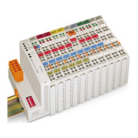
WAGO 750-842 User's Installation And Configuration (335 pages)
Modular I/O System Ethernet TCP/IP
Brand:
WAGO
| Category:
I/O Systems
| Size: 3.73 MB
Table of Contents
Table of Contents
3
1 Important Comments
5
Legal Principles
5
Personnel Qualification
5
Intended Use
5
Scope
6
Symbols
6
Font Conventions
7
Number Notation
7
Abbreviation
7
2 The WAGO-I/O-SYSTEM 750
8
System Description
8
Coupler/Controller
8
Setting up a Fieldbus Node with the WAGO-I/O-SYSTEM
8
I/O Modules
9
End Module
9
Characteristics and Use of the Controllers
9
Installation
10
Safty Notes
10
Mechanical Installation
10
Coupler/Controller and Unlocking Lug
11
Releasing a I/O Module
11
Power Jumper Contacts
12
Data Contacts
12
Electrical Installation
13
Wire Connection
13
Inserting Conductor End
13
Change Fuse
14
Removing the Fuse Holder
14
Opening the Fuse Holder
14
Power Supply
15
System Supply Voltage
16
Supply Voltage Field Side
17
Manufacturing Number
18
Technical Data
19
Mechanic
19
Wire Range
19
Contacts
19
Dimensions
20
Safe Electrical Isolation
20
Degree of Protection
20
3 Fieldbus Coupler / Controller
21
Fieldbus Coupler 750-342
21
Description
22
Fieldbus Coupler ETHERNET TCP/IP
23
Hardware
23
View
23
Device Supply
24
Fieldbus Connection
24
RJ45-Connector and RJ45 Connector Configuration
24
Configuration Interface
25
Display Elements
25
Hardware Address (MAC-ID)
25
Operating System
26
Process Image
27
Example of a Process Input Image
28
Example of a Process Output Image
29
Process Data Architecture for MODBUS/TCP
30
750-404, /000-00X Counter Modules
31
750-404/000-005 2 Channel up Counter 16 Bit
31
750-511, /000-002 2-Channel Digital Pulsewidth Module
32
750-630, /000-00X SSI Encoder Interface 24 Bit
32
750-631, /000-001 Incremental Encoder Interface
33
750-650 RS232 Interface Module
34
750-650/000-001 RS232 Interface Module 5 Byte
34
750-651 TTY-,20 Ma Current Loop
34
750-653 RS485 Interface Module
34
Data Exchange
35
Addressing
36
Addressing the I/O Modules
36
Memory Areas
36
Address Range
37
Address Range for I/O Module Data
37
I/O Module Data Width
37
Data Exchange between MODBUS Master and I/O Modules
38
Data Exchange between the MODBUS Master and I/O Modules
38
Connecting PC and Fieldbus Node
39
Note the MAC-ID and Establish the Fieldbus Node
39
Starting up ETHERNET TCP/IP Fieldbus Nodes
39
Allocating the IP Address to the Fieldbus Node
40
Determining IP Addresses
40
Bootp Table
41
Bootp Server
42
Dialog Window of the WAGO Bootp Server with Messages
43
Example for the Function Test of a Fieldbus Node
43
Testing the Function of the Fieldbus Node
43
Information on the Fieldbus Coupler (Coupler and Network Details)
44
Information on the Fieldbus Node (Terminal Status)
44
Reading out the Information as HTML Pages
44
Reading out the Information Via the HTTP Protocol
44
Blink Code
45
Display Elements 750-342
45
LED Display
45
Fieldbus Status
46
Node Status
46
Fault Code 1: Hardware and Configuration Fault
47
Fault Code 2: Fault in Programmed Configuration
47
Fault Message Via Blink Code from the I/O-LED
47
Signalling of the LED for Indication of the Node Status
47
Example for a Fault Message
48
Fault Code 4: Internal Bus Data Fault
48
Fault Code 6: Fieldbus Specific Error
48
Fault Code 7: I/O Module Is Not Supported
48
Fault Behavior
49
Fieldbus Failure
49
Internal Bus Fault
49
Approvals
50
System Data
50
Technical Data
50
Fieldbus Controller 750-842
51
Description
52
Fieldbus Controller ETHERNET TCP/IP
53
Hardware
53
View
53
Device Supply
54
Display Elements
55
Fieldbus Connection
55
Configuration and Programming Interface
56
Operating Mode Switch
56
Hardware Address (MAC-ID)
57
Operating System
58
PLC Cycle
58
Start-Up
58
Process Image
60
Example of a Process Input Image
61
Example of a Process Output Image
62
Process Data Architecture for MODBUS/TCP
63
Data Exchange
69
Memory Areas
70
Addressing
71
Data Exchange between Master and I/O Modules
74
Data Exchange between PLC Functionality (CPU) and I/O Modules
75
Data Access by the MODBUS Master
76
Data Exchange between Master and PLC Functionality (CPU)
76
Programmable Fieldbus Controller
76
Common Access of MODBUS Master and PLC Functionality to Outputs
77
Address Review
78
Connecting PC and Fieldbus Node
79
Note the MAC-ID and Establish the Fieldbus Node
79
Starting up ETHERNET TCP/IP Fieldbus Nodes
79
Allocating the IP Address to the Fieldbus Node
80
Determining IP Addresses
80
Testing the Function of the Fieldbus Node
83
Viewing the HTML Pages
84
Programming the PFC with WAGO-I/O-PRO 32
86
WAGO-I/O-PRO 32 Library Elements for ETHERNET
86
Ethernet.lib
87
Ethertcpmodbus.lib
87
IEC 61131-3-Program Transfer
88
Internal Types for Ethertcpmodbus.lib
88
Transmission Via the Serial Interface
89
Transmission by the Fieldbus
90
Blink Code
91
LED Display
91
Fieldbus Status
92
Node Status
92
Fault Message Via Blink Code from the I/O-LED
94
Supply Voltage Status
95
Fault Behavior
96
Fieldbus Failure
96
Internal Bus Fault
96
Technical Data
97
4 O Modules
98
I/O Modules-Review
99
Digital Inputs
99
Digital Outputs
99
Analog Inputs
100
Analog Outputs
100
Supply and End Modules
101
Terminal Blocks for Encoder and Resolvers
101
Special Terminal Blocks
101
Digital Inputs
102
Channel Digital Inputs
103
Technical Description
103
Counter Modules
107
Organization of the Input and Output Data
109
Setting the Counter
109
Blocking the Counter
109
Setting the Outputs
109
Variation
111
Counter with Enable Input 750-404/000-001
111
Peak Time Counter 750-404/000-002
112
Frequency Counter Module
113
Functional Description
115
Timing Diagram for Process Data Update Sequence
115
Structure of CONTROL and STATUS Byte
116
Structure of the Input and Output Data
117
Up/Down Counter with Switching Outputs
118
Switching the Outputs Dependent of the Counter
119
Example How to Activate the Digital Outputs
119
2 Channel up Counter 16 Bit
120
2 Channel Digital Inputs
130
4 Channel Digital Inputs
132
Digital Outputs
136
2 Channel Digital Outputs
137
4 Channel Digital Outputs
139
Parameterizing the Period/Basic Frequency
150
Parameterizing the Registers
151
Control Byte
151
Status Byte
151
Register 2 Write Mode
152
Organization of the In- and Output Data
153
Digital Output Relay
154
Relays in the Modules 750-512
156
Relays in the Modules 750-513
159
Analog Inputs
168
Analog Outputs
213
Supply and End Modules
221
Terminal Blocks for Encoder and Resolvers
233
Special Terminal Blocks
242
5 Ethernet
265
Network Architecture - Principles and Regulations
266
Network Communication
274
Channel Access Method
274
Communication Protocols
274
Ethernet
276
ETHERNET Address (MAC-ID)
276
ETHERNET Packet
276
IP-Protocol
276
IP Addresses
277
Key Data
278
Subnets
278
Subnet Mask
279
Gateway
280
IP Packet
280
TCP Protocol
280
TCP Port Numbers
280
TCP Segment
281
Udp
281
Icmp
281
Application Protocols
282
Modbus/Tcp
282
MODBUS TCP Segment
282
Bootstrap Protocol (Bootp)
283
Hypertext Transfer Protocol (HTTP)
283
6 Common MODBUS Functions
284
List of the MODBUS Functions in the Fieldbus Coupler and Controller
284
Use of the MODBUS Functions
285
Description of the MODBUS Functions
286
Function Code FC1 (Read Coils)
287
Request
287
Response
287
Function Code FC2 (Read Discrete Inputs)
288
Function Code FC3 (Read Multiple Registers)
289
Function Code FC4 (Read Input Registers)
290
Function Code FC5 (Write Coil)
291
Function Code FC6 (Write Single Register)
292
Function Code FC7 (Read Exception Status)
293
Function Code FC15 (Force Multiple Coils)
294
Function Code FC16 (Write Multiple Registers)
295
Function Code FC11 (Get Comm Event Counter)
296
Function Code FC23 (Read/Write Multiple Registers)
297
Watchdog (Fieldbus Failure)
298
Watchdog Register
299
Register Address 0X1000
299
Register Address 0X1001
299
Register Address 0X1002
299
Register Address 0X1004
300
Register Address 0X1005
300
Register Address 0X1006
300
Register Address 0X1007
300
Diagnostic Function
301
Register Address 0X1020
301
Register Address 0X1021
301
Configuration Function
302
Register Address 0X1022
302
Register Address 0X1023
302
Register Address 0X1024
302
Firmware Information
303
Register Address 0X2010
303
Register Address 0X2011
303
Register Address 0X2012
303
General Registers
304
Register Address 0X2000
304
Register Address 0X2001
304
Register Address 0X2002
304
Special PFC Register (Only for Controller 750-842)
305
7 Application Examples
306
Test of MODBUS Protocol and Fieldbus Nodes
306
Visualization and Control Using SCADA Software
306
Example of the MODBUS Function Code
308
Example of User Software
308
8 Application in Explosive Environments
309
Protective Measures
309
Classification Meeting CENELEC and IEC
309
Foreword
309
Explosion Protection Group
310
Minimal Ignition Energy of Representative Types of Gases
310
Explosive Areas Subject to Air-Borne Dust
310
Explosive Areas Resulting from Gases, Fumes or Mist
310
Unit Categories
311
Temperature Classes
312
Explosion Group
312
Types of Ignition Protection
313
Classifications Meeting the NEC 500
314
Divisions
314
Explosion Protection Groups
314
Identification
316
According to CENELEC and IEC
316
Example for Lateral Labeling of Bus Modules
316
According to NEC 500
317
Installation Regulations
318
9 Glossary
320
Baseband
320
Bit
320
Bit Rate
320
Client
321
Coaxial Cable
321
Csma/CD
321
Deterministic ETHERNET
321
ETHERNET Standard
322
Fieldbus
322
Firewall
322
Frame
322
Header
323
Host Computer / Subscriber
323
Html
323
Http
323
IAONA Europe
324
ICMP Protocol
324
Iec 61131-3
324
Ieee
324
Intranet
325
Isa
325
ISO/OSI Reference Model
325
Lan
325
Ms-Dos
326
Open MODBUS/TCP Specification
326
Ping Command
326
Predictable ETHERNET
326
Repeater
327
RFC Specifications
327
RJ45 Connector
327
Router
327
Scada
328
Segment
328
Server
328
Structured Cabling
328
S-Utp
329
Switch
329
Switched ETHERNET
329
TCP/IP Protocol Stack
329
UDP Protocol
330
Wago-I/O-Pro 32
330
Web Browser
330
Wide Band
330
10 Literature List
331
11 Index
332
Advertisement
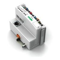
WAGO 750-842 Quick Start Quide (14 pages)
ETHERNET Fieldbus Controller
Brand:
WAGO
| Category:
I/O Systems
| Size: 0.37 MB
Table of Contents
Table of Contents
3
1 Important Comments
4
Legal Principles
4
Copyright
4
Personnel Qualification
4
Intended Use
4
Symbols
5
Number Notation
5
Safety Notes
6
Scope
6
2 Quick Start
7
Node Assembly
7
Ethernet Network Start-Up
8
The First Program
10
Program Download to the Controller 750-842
12
Modbus/Tcp DLL Application Examples
13
Advertisement
Related Products
WAGO 750-8207
WAGO 750-860
WAGO 750-841
WAGO 750-872/020-000
WAGO 750-830
WAGO 750-882
WAGO 750-8 Series
WAGO 750-871
WAGO 750-8210/040-000
WAGO LONWORKS 750-819
WAGO Categories
I/O Systems
Control Unit
Power Supply
Switch
Controller
More WAGO Manuals
Login
Sign In
OR
Sign in with Facebook
Sign in with Google
Upload manual
Upload from disk
Upload from URL