Sign In
Upload
Manuals
Brands
WAGO Manuals
I/O Systems
750-841
WAGO 750-841 Fieldbus Controller Manuals
Manuals and User Guides for WAGO 750-841 Fieldbus Controller. We have
1
WAGO 750-841 Fieldbus Controller manual available for free PDF download: Manual
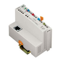
WAGO 750-841 Manual (243 pages)
Modular I/O-System; ETHERNET TCP/IP
Brand:
WAGO
| Category:
I/O Systems
| Size: 2.93 MB
Table of Contents
Table of Contents
3
1 Important Comments
5
Legal Principles
5
Personnel Qualification
5
Intended Use
5
Symbols
6
Font Conventions
6
Number Notation
6
Safety Notes
7
Scope
8
Important Comments for Starting up
8
Abbreviation
8
2 The WAGO-I/O-SYSTEM 750
9
System Description
9
Fieldbus Node
9
Technical Data
10
Mechanical Strength
11
Safe Electrical Isolation
11
Degree of Protection
11
Maximum Power Dissipation of the Components
12
Dimensions
13
Manufacturing Number
13
Component Update
14
Update Matrix
14
Example: Manufacturing Number of a PROFIBUS Fieldbus Coupler 750-333
14
Storage, Assembly and Transport
15
Mechanical Setup
15
Total Expansion
15
Assembly Onto Carrier Rail
16
Carrier Rail Properties
16
WAGO DIN Rail
17
Spacing
17
Plugging and Removal of the Components
18
Coupler/Controller and Unlocking Lug
18
Removing Bus Terminal
18
Assembly Sequence
19
Internal Bus / Data Contacts
20
Data Contacts
20
Power Contacts
21
Power Jumper Contacts
21
Example for the Arrangement of Power Contacts
21
Wire Connection
22
CAGE CLAMP Connection
22
Power Supply
23
Isolation
23
System Supply
24
System Voltage
24
Field Supply
27
Field Supply (Sensor / Actuator)
27
Fusing
28
Supply Module with Fuse Carrier (Example 750-610)
28
Removing the Fuse Carrier
29
Opening the Fuse Carrier
29
Change Fuse
29
Fuse Modules for Automotive Fuses, Series 282
30
Fuse Modules with Pivotable Fuse Carrier, Series 281
30
Fuse Modules, Series 282
30
Supplementary Power Supply Regulations
31
Power Supply Concept
31
Supply Example
32
Power Supply Unit
33
Grounding
34
Grounding the DIN Rail
34
Framework Assembly
34
Insulated Assembly
34
Grounding Function
35
Carrier Rail Contact
35
Grounding Protection
36
Ring-Feeding
36
Shielding (Screening)
37
Bus Conductors
37
Signal Conductors
37
WAGO Shield (Screen) Connecting System
38
Assembly Guidelines / Standards
38
Application of the WAGO Shield (Screen) Connecting System
38
3 Fieldbus Controller
39
Description
40
Compatibility
41
Hardware
42
View
42
Fieldbus Controller ETHERNET TCP/IP
42
Device Supply
43
Display Elements
44
Fieldbus Connection
44
RJ45-Connector and RJ45 Connector Configuration
44
Configuration and Programming Interface
45
Operating Mode Switch
46
Hardware Address (MAC-ID)
47
Operating System
48
PLC Cycle
48
Start-Up
48
Controller Operating System
49
General Structure
50
Process Image
50
Example of a Process Input Image
52
Example of a Process Output Image
53
1 Channel Digital Input Module with Diagnostics
54
Digital Input Modules
54
Fieldbus Specific Process Data Architecture for MODBUS/TCP
54
2 Channel Digital Input Modules
55
2 Channel Digital Input Modules with Diagnostics
55
4 Channel Digital Input Modules
56
8 Channel Digital Input Modules
56
Digital Output Modules
56
2 Channel Digital Output Modules
57
Input Process Image
57
Output Process Image
57
4 Channel Digital Output Modules
58
Analog Input Modules
59
Channel Digital Output Module
59
Channel Analog Input Module
60
Specialty Modules
61
Counter Modules
62
Pulse Width Modules
63
Input and Output Process Image
64
Serial Interface Modules with Alternative Data Format
64
Serial Interface Modules with Standard Data Format
64
Data Exchange Module
65
SSI Transmitter Interface Modules
65
Incremental Encoder Interface Modules
66
Enocean Radio Receiver
68
MP Bus Master Module
68
AS-Interface Master Module
69
System Modules
69
System Modules with Diagnostics
69
Data Exchange
70
Memory Areas
71
Memory Areas and Data Exchange for a Fieldbus Controller
71
Programmable Fieldbus Controller
71
Address Range
73
Addressing the I/O Modules
73
I/O Module Data Width
73
Word 0-255: First Address Range I/O Module Data:
74
Word 1276-1531: Address Range for Ethernet/Ip Fieldbus Data:
74
Word 256-511: Address Range for MODBUS/TCP Fieldbus Data:
74
Word 512-1275: Second Address Range I/O Module Data:
74
Absolute Addresses
75
Overview of the IEC 61131-3 Address Ranges
75
Data Exchange between MODBUS TCP Master and I/O Modules
76
Data Exchange between MODBUS Master and I/O Modules
77
Data Exchange between Ethernet IP Master and I/O Modules
78
Data Exchange between PLC Functionality (CPU) and I/O Modules
79
Data Access by the MODBUS TCP Master
80
Data Access by the PLC Functionality
80
Data Exchange between Master and PLC Functionality (CPU)
80
Example MODBUS TCP Master and PLC Functionality (CPU)
80
Comparison of MODBUS TCP Addresses and IEC 61131-3 Addresses
82
Word Access
82
Bit Access
83
Connecting PC and Fieldbus Node
85
Starting up an ETHERNET TCP/IP Fieldbus Node
85
Variation 1: Start up with the WAGO Ethernet Settings
85
Testing the Function of the Fieldbus Node
86
Note the MAC-ID and Establish the Fieldbus Node
87
Variation 2:Starting up with the WAGO Bootp Server
87
Allocating the IP Address to the Fieldbus Node
88
Determining IP Addresses
88
Bootp Table
89
Bootp Server
90
Deactivating the Bootp Protocol
92
Programming the PFC with WAGO-I/O-PRO CAA
94
Configuration with the WAGO-I/O-PRO CAA I/O-Configurator
95
Configuration with the “EA-Config.xml” File
97
WAGO-I/O-PRO CAA Library Elements for ETHERNET
98
Flowchart of an IEC Task
99
Some Basic Facts about IEC Tasks
99
Overview of the most Important Task Priorities
100
System Events
100
IEC 61131-3-Program Transfer
102
Transmission Via the Serial Interface
103
Transmission by the Fieldbus
104
Information on the Web-Based Management System
105
Tcp/Ip
105
Port
106
Snmp
106
Clock
107
Security
107
Watchdog
107
Ethernet
108
Features
109
Plc
109
I/O Config
110
Samples
111
Display Elements 750-841
112
LED Display
112
Fieldbus Status
113
Node Status - Blink Code from the 'I/O' LED
114
Signalling of the LED for Indication of the Node Status
114
Fault Message of the 'I/O' LED
115
Supply Voltage Status
120
Usr'-Led
120
Fault Behavior
121
Fieldbus Failure
121
Internal Bus Fault
121
Technical Data
122
I/O Modules
123
General
123
Digital Input Modules
123
Digital Output Modules
125
Analog Intput Modules
126
Analog Output Modules
127
Special Modules
127
System Modules
128
5 Ethernet
129
General
129
Network Architecture - Principles and Regulations
130
Connection Principle of a Fieldbus Node for a Network Architecture
130
General ETHERNET Transmission Standards
131
10Base-T, 100Basetx
131
ETHERNET Transmission Standards
131
Wiring of the Fieldbus Nodes
132
Direct Connection of a Node with Crossover Cable
132
Connection of a Node by Means of a Hub with Parallel Cables
132
Network Topologies
133
Star Topology
133
Tree Topology
134
Rule
134
Cabling Guidelines
135
Coupler Modules
135
Comparison of Coupler Modules for Networks
135
Important Terms
136
Data Security
136
Real-Time Ability
136
Shared ETHERNET
136
Deterministic ETHERNET
137
Switched ETHERNET
137
Principle of Switched ETHERNET
137
Network Communication
138
Protocol Layer Model
138
Application Protocols
139
Communication Protocols
140
ETHERNET Address (MAC-ID)
141
ETHERNET Packet
141
Channel Access Method
141
IP-Protocol
142
IP Addresses
142
Subnets
144
Subnet Mask
144
Raw Ip
145
Gateway
145
IP Packet
145
IP Multicast
146
TCP Protocol
146
TCP Port Numbers
146
TCP Segment
147
Udp
147
Ar
147
ARP (Address Resolution Protocol).
147
Modbus
148
MODBUS TCP Segment
148
MODBUS/TCP Header
148
Ethernet/Ip
149
Bootp (Bootstrap Protocol)
150
HTTP (Hypertext Transfer Protocol)
151
DHCP (Dynamic Host Configuration Protocol)
151
DNS (Domain Name Systems)
152
SNTP-Client (Simple Network Time Protocol)
153
Configuration of the SNTP Client
153
FTP-Server (File Transfer Protocol)
153
SNMP V1 (Simple Network Management Protocol)
155
Configuration of SNMP
155
Description of MIB II
155
System Group
156
Interface Group
156
Address Translation Group
157
IP Group
158
Iproute Table
159
Ipnettomediatable
159
ICMP Group
160
TCP Group
161
UDP Group
161
SNMP Group
162
EGP-Group
163
Traps
163
SMTP (Simple Mail Transfer Protocol)
163
6 MODBUS Functions
164
List of the MODBUS Functions in the Fieldbus Controller
164
General
164
Use of the MODBUS Functions
165
Description of the MODBUS Functions
166
Function Code FC1 (Read Coils)
167
Function Code FC2 (Read Input Discretes)
168
Function Code FC3 (Read Multiple Registers)
169
Function Code FC4 (Read Input Registers)
170
Function Code FC5 (Write Coil)
171
Function Code FC6 (Write Single Register)
172
Function Code FC11 (Get Comm Event Counter)
173
Function Code FC15 (Force Multiple Coils)
174
Function Code FC16 (Write Multiple Registers)
175
Function Code FC22 (Mask Write Register)
176
Function Code FC23 (Read/Write Multiple Registers)
177
MODBUS Register Mapping
178
Register (Word) Access Reading
178
Bit Access Reading
179
Bit Access Writing
179
Internal Variables
179
Wago-I/O-System
180
Description of the Internal Variables
181
Watchdog Register
181
Diagnostic Functions
185
Configuration Functions
185
Firmware Information
188
Constant Registers
189
7 Ethernet/Ip (Ethernet/Industrial Protocol)
191
General
191
Characteristics of the Ethernet/Ip Protocol Software
192
Object Model
193
Classes
194
CIP Common Classes
194
WAGO Specific Classes
194
Identity
196
Common Services
197
Message Router
197
Assembly
198
Static Assembly Instances
198
Port Class
201
TCP/IP Interface
202
Ethernet Link
203
Coupler Configuration
203
Analog Output Point
207
Discrete Input Point Extended 1..3
207
Module Configuration
208
Input Fieldbus Variable USINT
208
Input Fieldbus Variable USINT Extended 1
209
Output Fieldbus Variable USINT Extended 1
210
Input Fieldbus Variable UINT
211
Output Fieldbus Variable UINT Extended 1
212
Input Fieldbus Variable UDINT
212
8 Application Examples
214
Test of MODBUS Protocol and Fieldbus Nodes
214
Visualization and Control Using SCADA Software
214
Example of the MODBUS Function Code
216
Example of User Software
216
9 Use in Hazardous Environments
217
Protective Measures
217
Classification Meeting CENELEC and IEC
217
Foreword
217
Explosive Areas Subject to Air-Borne Dust
218
Explosion Protection Group
218
Unit Categories
219
Temperature Classes
219
Types of Ignition Protection
220
Classifications Meeting the NEC 500
221
Divisions
221
Explosion Protection Groups
221
Identification
223
According to CENELEC and IEC
223
Installation Regulations
225
10 Glossary
227
11 Literature List
239
12 Index
240
Wago-I/O-System
241
Advertisement
Advertisement
Related Products
WAGO 750-842
WAGO 750-8207
WAGO 750-860
WAGO 750-872/020-000
WAGO 750-830
WAGO 750-882
WAGO 750-8 Series
WAGO 750-871
WAGO 750-8210/040-000
WAGO LONWORKS 750-819
WAGO Categories
I/O Systems
Control Unit
Power Supply
Switch
Controller
More WAGO Manuals
Login
Sign In
OR
Sign in with Facebook
Sign in with Google
Upload manual
Upload from disk
Upload from URL