Sign In
Upload
Manuals
Brands
WAGO Manuals
I/O Systems
750-337
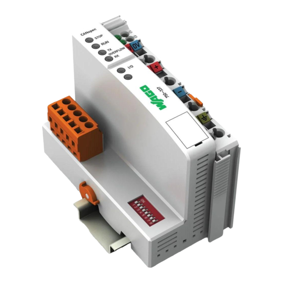
WAGO 750-337 Fieldbus Coupler CANopen Manuals
Manuals and User Guides for WAGO 750-337 Fieldbus Coupler CANopen. We have
2
WAGO 750-337 Fieldbus Coupler CANopen manuals available for free PDF download: Technical Description, Instruction Manual
WAGO 750-337 Technical Description (192 pages)
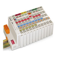
Modular I/O System CANopen
Brand:
WAGO
| Category:
I/O Systems
| Size: 2.12 MB
Table of Contents
Table of Contents
3
1 Important Notes
7
Legal Principles
7
Copyright
7
Personnel Qualification
7
Conforming Use of Series 750
8
Technical Condition of the Devices
8
Standards and Regulations for Operating the 750 Series
8
Symbols
9
Safety Information
10
Font Conventions
11
Number Notation
11
2 The WAGO-I/O-SYSTEM 750
12
System Description
12
Scope
12
Technical Data
13
Manufacturing Number
19
Component Update
20
Storage, Assembly and Transport
20
Mechanical Setup
21
Installation Position
21
Total Expansion
21
Assembly Onto Carrier Rail
22
Carrier Rail Properties
22
WAGO DIN Rail
23
Spacing
23
Plugging and Removal of the Components
24
Assembly Sequence
25
Internal Bus/Data Contacts
26
Power Contacts
27
Wire Connection
28
Power Supply
29
Isolation
29
System Supply
30
Connection
30
Alignment
31
Field Supply
33
Connection
33
Fusing
34
Supplementary Power Supply Regulations
37
Supply Example
38
Power Supply Unit
39
Grounding
40
Grounding the DIN Rail
40
Framework Assembly
40
Insulated Assembly
40
Grounding Function
41
Grounding Protection
42
Shielding (Screening)
43
General
43
Bus Conductors
43
Signal Conductors
43
WAGO Shield (Screen) Connecting System
44
Assembly Guidelines/Standards
44
Abbreviation
45
3 Fieldbus Coupler
46
Fieldbus Coupler 750-337, 750-338
46
Description
46
Hardware
47
View
47
Variations
48
Device Supply
48
Fieldbus Connection
49
Display Elements
50
Configuration Interface
51
Hardware Address (Module ID)
51
Setting the Baud Rate
52
Operating System
53
Process Image
54
Structure in Principle
54
Data Exchange
54
Communication Objects
55
Communication Interfaces
55
Memory Areas
55
Addressing
56
Starting up a Canopen Fieldbus Node
59
Connecting the PC and Fieldbus Node
59
Checking and Setting the Baud Rate
59
Setting the Module ID
60
Changing to the OPERATIONAL Status
61
Switching on the Analog Input Data
61
Application Specific Mapping
62
LED Display
65
Fieldbus Status
66
Node Status - Blink Code of the 'I/O' LED
67
Supply Voltage Status
72
Technical Data
74
Description
76
Network Architecture
77
Transmission Media
77
Type of Cable
77
Maximum Bus Length
77
Required Conductor Cross Section
78
Cabling
78
Network Topology
81
Interface Modules
82
Configuration Software
82
Network Communication
82
Communication Objects
83
Process Data Object - PDO
83
Service Data Object - SDO
84
Synchronization Object - SYNC
93
Emergency Object (EMCY)
94
Communication States of a Canopen Fieldbus Coupler/Controller
95
Canopen State Diagram
95
Initialization
95
Pre-Operational
96
Operational
96
Stopped
96
Network Management Objects
97
Module Control Protocols
97
Error Control Protocols
98
Node Guarding Protocol
99
Heartbeat Protocol
99
Bootup Protocol
100
Object Directory
100
Initialization
102
Communication Profile Area
106
Manufactor Specific Profile Area
117
Standard Device Profile Area - DS 401
129
PDO Transmission
137
Mapping
137
Transmit PDO1
138
Receive PDO1
139
Transmit PDO2
140
Receive PDO2
141
SYNC Monitoring
142
Node Guarding
142
Heartbeat Monitoring
144
Error Message (Emergency)
144
Diagnostic Message of I/O Modules
146
5 O Modules
148
Overview
148
Digital Input Modules
148
Digital Output Modules
150
Analog Intput Modules
151
Analog Output Modules
152
Special Modules
153
System Modules
154
Process Data Architecture for Canopen
155
Digital Input Modules
155
Digital Output Modules
157
Analog Input Modules
161
Analog Output Modules
162
Specialty Modules
163
System Modules
179
6 Use in Hazardous Environments
180
Foreword
180
Protective Measures
180
Classification Meeting CENELEC and IEC
180
Divisions
180
Explosion Protection Group
181
Unit Categories
182
Temperature Classes
182
Types of Ignition Protection
183
Classifications Meeting the NEC 500
184
Divisions
184
Explosion Protection Groups
184
Temperature Classes
185
Identification
186
For Europe
186
For America
187
Installation Regulations
188
7 Glossary
190
8 Literature List
190
9 Index
191
Advertisement
WAGO 750-337 Instruction Manual (34 pages)
Connection Procedure of Bus Coupler and Pro-face display units supporting CANopen master for WAGO-I/O-SYSTEM 750
Brand:
WAGO
| Category:
Industrial Electrical
| Size: 0.66 MB
Table of Contents
Table of Contents
3
1 Devices in Use
5
2 Installation of GP-Pro EX Version 3.50
5
3 Creation of Screens/Programs
5
4 Flow of Canopen Setting with the Software
6
Displaying the I/O Driver Setting Screen
6
Importing an EDS File
6
Adding a Slave
8
Slave Configuration
9
PDO: Mapping Input and Output
10
Allocating I/O Variables to the I/O Tree
12
Master Configuration
13
Setting a Baud Rate
13
5 Relation between Objects and I/O Module
15
Catalog Manager
16
Device Operations
16
Catalog Operations
17
Slave Configuration
18
Parameters (PDO Settings)
18
Advanced Error Control
21
Advanced Object Configuration
22
Master Configuration
23
Network Settings
23
Error Control Overview
24
Advanced Object Configuration
24
6 PDO Protocol, SDO Protocol
25
PDO (Process Data Object) Protocol
25
SDO (Service Data Object) Protocol
25
7 O Driver Instructions
26
Sdor, Sdow
26
Dgmt, Dgsl
28
8 Transferring I/O Firmware
28
9 AGP-3****-CA1M/LT Unit
29
Offline Menu
29
10 Installation of WAGO 750-337
31
Hardware Structure
31
Connector Diagram
32
Display Elements
33
Hardware Address (Module ID)
33
Setting the Baud Rate
34
Advertisement
Related Products
WAGO 750-338
WAGO 750-370
WAGO 750-342
WAGO 750-344
WAGO 750-341
WAGO 750-377
WAGO 750-354/000-001
WAGO 750-312
WAGO 750-352/040-000
WAGO LONWORKS 750-319
WAGO Categories
I/O Systems
Control Unit
Power Supply
Switch
Controller
More WAGO Manuals
Login
Sign In
OR
Sign in with Facebook
Sign in with Google
Upload manual
Upload from disk
Upload from URL