
Related Manuals for WAGO 750-337


Summary of Contents for WAGO 750-337
- Page 1 Connection Procedure of WAGO CANopen 750-337 Bus Coupler and Pro-face display units supporting CANopen master Instruction Manual Version 1.2 (2017.09.15)
- Page 2 Copyright © 2008 by WAGO Kontakttechnik GmbH All rights reserved. WAGO Kontakttechnik GmbH Hansastraße 27 D-32423 Minden Phone: +49 (0) 571/8 87 – 0 Fax: +49 (0) 571/8 87 – 1 69 E-Mail: info@wago.com Web: http://www.wago.com Every conceivable measure has been taken to ensure the correctness and completeness of this documentation.
-
Page 3: Table Of Contents
I/O driver instructions ..........................22 SDOR, SDOW ............................. 22 DGMT, DGSL ............................. 24 Transferring I/O firmware ........................24 AGP-3****-CA1M/LT unit ........................25 Offline menu ............................25 Installation of WAGO 750-337 ......................27 10.1 Hardware structure ........................... 27 10.2 Connector diagram ........................... 28 10.3 Display elements .......................... -
Page 5: Devices In Use
Devices in use This manual refers to the structure using the following devices and equipments. - WAGO CANopen Bus Coupler 750-337 and the following I/O modules 750-337: CANopen Bus Coupler 750-430: 8-Channel Digital Input Module 750-530: 8-Channel Digital Output Module... -
Page 6: Flow Of Canopen Setting With The Software
When using LT3000 series and SP5000 series Power Box, click the [External Driver 1] tab. When using LT4000 series, click the [Int. Driver 2] tab. Importing an EDS file This section shows the procedure to import an EDS file of a WAGO 750-337 slave. 1) In the [I/O Driver] screen, click [Catalog manager]. - Page 7 2) Click [Import]. 3) The [Open] dialog box will appear. Specify the 750-337.EDS file in the save-in location. Click [Open], and the file will be registered into the [Catalog manager].
-
Page 8: Adding A Slave
1) In the [I/O Driver] screen, click [Settings], and the [Network configuration] window will appear. 2) Select the item whose Key is 750-337 from the [Registered devices] list and click [Add slave], and “WAGO 750-337” will be added in the [Assigned slaves] list. -
Page 9: Slave Configuration
Slave configuration - Click [Slave configuration]. - The [Slave configuration] dialog box will appear. -
Page 10: Pdo: Mapping Input And Output
PDO: Mapping input and output Set PDOs (Process Data Objects), as continuous communication data. For WAGO 750-337, the standard inputs, which are digital inputs, start from “0x6000” and the standard outputs, which are digital outputs, from 0x6200. As an example of inputs, select “Index = 0x6000.1” from the list of the [Available objects from device profile] in the [Parameters] tab. - Page 11 As an example of outputs, select “Index = 0x6200.1” from the list of the [Available objects from device profile” on the [Parameters] tab. Select “RPDO0” in the [Configured objects] and click [Map], and “[0x6200.1] 1.digital output block” will be appended under “RPDO0”. Set the [Data representation] in the [Setting] area to “Bit”...
-
Page 12: Allocating I/O Variables To The I/O Tree
Allocate I/O variables after the PDO settings (mapping). 1) Click [I/O Screen] in the [I/O Driver] screen. 2) The [WAGO CANopen Buskoppler STD] tree will be shown. As an example, allocate variables to four lower bits of 8-channel inputs. Set the variables from “INPUT_00” to “INPUT_03” for the items from “Bit-0” to “Bit-3”, which are under “TPDO0”. -
Page 13: Master Configuration
Master configuration - In the [I/O Driver] screen, click [Settings]. 4.5.1 Setting a baud rate In the Master configuration, you can make a baud rate settings. Baud rate settings on a slave unit can be made with the DIP switches on it. 1) In the [Network configuration] window, click [Master configuration]. - Page 14 2) In the [Master configuration] dialog box, specify the [Baud rate]. [Note] When LT4000 series is used, the baud rate cannot be set to 500kbps and 1000kbps.
-
Page 15: Relation Between Objects And I/O Module
The relation between objects and I/O modules is as follows. Please refer to the Modular I/O System CANopen 750-337 Manual for the details. The values in parentheses are ones in the manufacturer area; for example, 0x6000 and 0x2000 are the same value. -
Page 16: Catalog Manager
Details of settings with the software Catalog manager 5.1.1 Device operations * Import Imports an EDS (Electronic Data Sheet) file. The EDS file is registered in the Catalog manager of GP-Pro EX, and the contents in the EDS file is shown in the Catalog manager. -
Page 17: Catalog Operations
5.1.2 Catalog operations * Export Exports registered devices into one file (a catalog file; .cat). By doing so, it will be easier to make the same environment in another PC. * Import Imports a catalog file. -
Page 18: Slave Configuration
Slave configuration 5.2.1 Parameters (PDO settings) Up to 8 bytes (64 bits) of data can be assigned per PDO. The transmission type can be set by each PDO. - In the [Network configuration] window, click [Slave configuration]. In the [Slave configuration] dialog box, select “TPDO0”... - Page 19 Device type Vendor ID Product code Revision number [NOTE] Check off the [Revision number] when connecting with 750-337. When connecting with WAGO 750-337, the Device type cannot be selected. The imported EDS file identifies if each item is enabled or disabled.
- Page 20 All parameters are restored. Man. 4: restore manufacturer defined default parameters For WAGO 750-337, “Only Comm” and “Only App” are not supported. * NOTE Even if you set the object 0x6206, Error Mode Output 8-Bit, which is to retain the transmission of...
-
Page 21: Advanced Error Control
5.2.2 Advanced error control * HeartBeat Each node (the master and slaves) sends heartbeat messages. By monitoring (receiving) heartbeat messages, the master can check each node is active. The producer is the one that sends messages, and the consumer is the one that receives the messages. Currently, not NodeGuard but HeartBeat is recommended to use. -
Page 22: Advanced Object Configuration
* NodeGuard The master unit monitors slaves by polling (guarding) for the time of the Guard time multiplied by the Life time factor. 5.2.3 Advanced object configuration The Advanced Object Configuration tab shows the object list of the slave unit. The contents of objects vary depending on the type of the slave unit. -
Page 23: Master Configuration
Master configuration 5.3.1 Network settings * Baud rate Select the baud rate of the master unit. 50kbps to 1000kbps (default: 250kbps) [Note] When LT4000 series is used, the baud rate cannot be set to 500kbps and 1000kbps. * Global SYNC period Set the send cycle time of SYNC messages. -
Page 24: Error Control Overview
Reset all nodes Treat the slave individually (default) For WAGO 750-337, use the default because DS302 is not supported. If you select [Treat the slave individually], each slave unit sends the reset signal, not the master unit sends the reset signal by broadcast. -
Page 25: Pdo Protocol, Sdo Protocol
PDO protocol, SDO protocol PDO (Process Data Object) protocol The PDO protocol is used for communicating data such as digital inputs and outputs continuously. SDO (Service Data Object) protocol The SDO protocol is used for communicating data not necessary to be sent continuously, such as infrequent changes of setting values. -
Page 26: O Driver Instructions
I/O driver instructions SDOR, SDOW Reads from / writes to objects of the slave unit. SDOR (SDO Read) index number of the object sub index number of the object node ID length (byte number) of the object access location to store read data (offset number of #L_IOMasterDrv[]) error code... - Page 27 SDOW (SDO Write) index number of the object sub index number of the object node ID length (byte number) of the object access location to store data to be written (offset number of #L_IOMasterDrv[]) error code...
-
Page 28: Dgmt, Dgsl
DGMT, DGSL Reads the status of the master unit / slave unit. DGMT (Diagnostic Master) status information event information DGSL (Diagnostic Slave) node ID slave diagnostic information Transferring I/O firmware Firmware for the CANopen board is not yet installed in CANopen units for AGP-3****-CA1M/LT by factory default. -
Page 29: Agp-3****-Ca1M/Lt Unit
AGP-3****-CA1M/LT unit Offline menu * Master Diagnostics, Master Configuration & Events These menus have the same contents as the DGMT instruction does, which is one of the I/O driver instructions. The Master Diagnostics screen includes status information and the Master Configuration & Events screen includes event information. - Page 30 * Slave Diagnostics This menu has the same contents as the DGSL instruction does, which is one of the I/O driver instructions. You can select the status of the slaves and check nodes in the list.
-
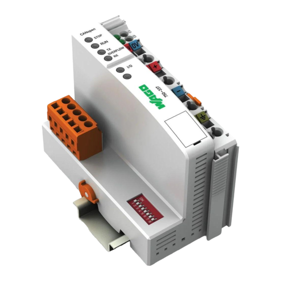
Page 31: Installation Of Wago 750-337
Bus Coupler End module Hardware is consist of the Bus Coupler 750-337, I/O modules Series 750 (up to 63 modules), and the End Module 750-600. DIs, DOs, AIs, and AOs can be mixed. Select necessary modules. A DC 24V power supply is required. -
Page 32: Connector Diagram
Diagram WAGO 750-337 * NOTE - To minimize the signal's reflections from the end of the cable, a line termination shall be placed close to the 2ends of the bus. Connect both ends of the twisted pair cable (CAN_H and CAN_L) to each LT. Use line terminationwhose resistance value is 120 Ω. -
Page 33: Display Elements
The binary significance of the individual DIP switches increases according to the switch number, i.e. the module ID 1 is set by DIP1 = ON, the module ID 8 by DIP4 = ON. The nodes of the WAGO-I/O-SYSTEM can have module IDs from 1 to 127. -
Page 34: Setting The Baud Rate
DIP value will be used to calculate the IDs which has been set during power ON. When switched off, the desired module ID can be set on the DIP. For more information on WAGO 750-337, visit WAGO's website. http://www.wago.com/wagoweb/documentation/index_e.htm...
Need help?
Do you have a question about the 750-337 and is the answer not in the manual?
Questions and answers